5133 no visible in LabVIEW
Hi all
Just bought a 2-channel digitizer high-speed USB-5133 and would pull in waveforms under LabVIEW 8.2. The instrument installed without event, works very well under NOR-SCOPE, is visible under the measurement and Automation explore (MAX version 4.5), passes all self-tests and test panels, but I have not been able to get LabView to talk about her. I'm new to LabVIEW 8.2, so I am probably doing something stupid. In general, I would use the DAQmx Wizard to create a simple analog VI. However, to do this requires that you use MAX to create a task DAQmx or Global virtual channel. Efforts to create such get as long as the dialog box to select a physical device and it lists no physical device available. No DAQmx handle seems to be able to navigate digitizer
I noticed that drop a dev1 IVI logical name dropdown list in the menu IS... Is this the road to get to this device?
Can anyone recommend a part of the documentation or example LabVIEW VI to speak directly to the USB-5133? We have need of a faster route to getting started he talks.
Thank you!!
You have an instrument of scope and which is not programmed with the DAQ Assistant or DAQmx driver. Yes, you can use the functions of class brought IVI to program or you can use the functions of NOR-Scope located on your Instrument with e/s > palette driver instruments. I do not have the NO-Scope driver installed on this pc, but I think that the example finder has some examples. Go to the hardware section of entrance and exit > Instrument Drivers
Tags: NI Products
Similar Questions
-
LabVIEW 2014 SP1, hardware and real-time PXI
I'm doing my third LabVIEW Wipe/reinstall in as many days, completely frustrated (and after several calls an hour with the support of NEITHER). Here's the situation:
I wrote a fairly large (1000 VI) project of Acquisition/control of our graduate students data used for behavioral experiment on sound localization. It was developed in 2012 LabVIEW with the module running on a PC/PXI system real time. It worked very well and was brought successfully under LabVIEW 2014 (with upgrades comparable to the software of the PXI.
About 18 months ago the students began to write their theses, and at one point stopped gathering data. Also, at some point, I upgraded the software on this system to LabVIEW 2014 SP1, but I am not sure that I never tested my software with this new system.
This week, I pulled up the system to use MAX to open some test on the PXI multifunction and DIO card panels to control manually one of the stimuli. I discovered that MAX could not communicate with the advice on the PXI system - he attributes them as devices VISA, indicating each Board with an icon with a red X means that he could not communicate with the IP that I had assigned to PXI. Yet, MAX (a) could "discover" this PXI, (b) MAX can 'see' its IP address, and (c) Windows could not only Ping the IP, but could FTP on the drive of the PXI and I could move files back and forth.
I did two sequences complete "Wipe/reinstall" using LabVIEW 2014 SP1, all giving the same result. I know it has worked in the past, including when I installed LabVIEW 2014 (without SP1), something I repeat myself now with my third installation. I discussed with OR (thin?) possibility that there is a "hidden defect" in the Distribution of the SP1, one that is visible to LabVIEW RT users using PXI hardware and go unnoticed because (a) install a few sites of LabVIEW versions SP1, (b) a minority use the RT Modules and (c) PXI is "old material".
If anyone has such a system or saw a similar problem, please answer. I'll do a follow-up post if I managed to 'fix' my system by this last reinstallation "a solution of worked before."
Bob Schor
Well, the answer is that, in my system, LabVIEW 2014 SP1 with LabVIEW Real-time connected to a PXI system does not appear to connect to boards plugged into the chassis. Returning to LabVIEW 2014 (fall release), installed in exactly in the same way that the three failed attempts of LabVIEW 2014 SP1, works immediately. Engineers OR will try to duplicate/verify/possibly patch? in this issue.
Bob Schor
-
cRIO-9073 not appearing is not in devices and Labview 2009 targets
In MAX, I show the following: a cRIO-9073 with NOR-RIO 3.0.0 installed. My system software has NEITHER-RIO 3.0. In LabView 2009, when I try and add the cRIO to my project in LabView 2009 in New-> targets and devices, I don't have a list in time real CompactRIO and my cRIO does not appear. I tried to add manually with its IP address, but it does not work either. I've updated the cRIO to LabView real-time 9.0 software.
Is there other software that I need to update on the cRIO so that it is visible in LabView 2009? Do I need a new version of NOR-RIO?
Thanks for any help.
Todd
I upgraded from NEITHER RIO NOR-RIO 3.2.1 3.0 and LabView 2009 seems happy.
See you soon,.
Todd
-
Programming computer laptop Wifi using Labview
Hi dear all, can someone guide me how can I program my laptop computer Wifi module to send and receive data through Labview programming. What tools or drivers should I me take his Express or other screws are visible in Labview. If possible, some codes an example or link to that knowledge base. This will help me understand the concepts of programming Wifi. Thanks Zdzislaw qureshi
Hi dear Dennis Knutson,
I tried screws from TCP/IP and to understand. But how can we make our PC Access point using Labview? Are there any specific screw init or some additional toolkit required to do this. Actually I want to PC to become the hot spot to be connected. My app will then scan him in serach and then sign in to do some data send and receive actions. You have little help for me in Labview.
For the wifi connection, I need to use the method of connectivity to Microsoft. How can I do this by Labview. I understood how to put IP LAN to detect in Labview only once I'm connected to the other PC via LAN wireless and wireless.
Thank you & best regards
Zdzislaw qureshi
-
Storage of Information within the screw
I have an interesting problem...
I have a VI that controls a subsystem. It has about 80 entries, when he used the subsystem with these entries programs. Entries are not homogeneous, they are information configuration and each means something different. This VI allows interactively and as part of a larger system. Since it has many entries I used clusters of group related entries.
As far as I can say LabVIEW applies the following scope rules when SubVIs are involved:
Controls that are wired to the login Panel
When a top-level VI calls a Subvi if highest level VI son an entry then the Sub - VI receives this value. If the VI more high-level wiring is not an entry, then the default value is used.
Controls that are not wired for the login Panel
When a VI is loaded into memory front panel is loaded with the default values, even if the VI is not visible. LabVIEW retains the values defined by the last use of the VI. It goes the same for registry entries to offset unwired.
The behavior of controls unwired is useful because it allows information to be stored, it allos "masking of information." In my application I can open the VI subsystem described above in an interactive way and set up some values. Screw top level then call that VI as usual. These screws of higher level need not know anything about the settings I changed. Where I work, this idea is used in the code for many years. It is similar to the "functional global variables" using terminals unwired-shift register.
Once a control should be wired to the component connector however everything changes, a value may not persist a use of the VI to the other. This is true even if the connector pane entry is left connected because otherwise LabVIEW use it * default value * not the existing value. Thus, all controls dealing with things my subsystem-specific low-level can be left unwired. Then all controls dealing with things higher level that allows to control the higher level screw must be wired and the highest level VI must assume responsibility for this information. Previous versions of the system that I mention did.
The problem with this plan is that the clusters. A cluster is either on a connector component or not, I can find no way to put a cluster on the connector pane entries but not others. Since I have so many entries, I need bunches. But, once I attribute a cluster to the connector pane the top-level screws must take responsibility for all its values. This means that I lose all the concealment of information that I had before and my code becomes much more complicated.
Someone at - he found a solution to this kind of problem?
I can draw out as example screws if people are interested.
-
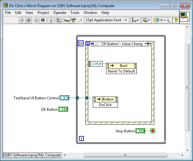
How can I join buttons visible teststand keyboard shortcuts in a labview user interface
On a normal labview VI, it is possible to configure the desired for example key navigation options assign a keyboard shortcut to a control. Is it possible somehow to assign a keyboard shortcut to the visible controls ActiveX Teststand i.eg. a basic custom user interface labview Teststand button?
Help, please

You may be able to do by cloning of each button, assign a shortcut to the clone, and then firing an event and call the method "DoClick' of the TestStand button - I say maybe because I can't verify the DoClick method will do what you want.
Obviously, you can hide the clones on the front panel if necessary.
-
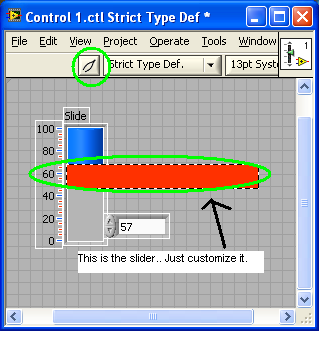
No visible cursor bar - LabVIEW 2009
Everything started working with cursors and I see a value of fill, but not the cursor. If I put the Red slider, then the transparent fill nothing. If I do the blue fill I see blue but no red cursor. Probably something small that I'm missing...
I'm tweaking of the coils in a filtering circuit, where each is twisted to increase the value of Q. So my goal is to have 2 sliders, which fills to display the current value and a separate slider that gets bumped up to the maximum value reached and won't go down.
In the joint I hooked 5 sliders with different padding just so I can try to see the cursor. If this works as I hope that I will offer 2 for max values and current values.
Thank you
JVH
Looks like you want to customize the appearance of your control. You can change the appearance of any part of a control, here is an example.
-
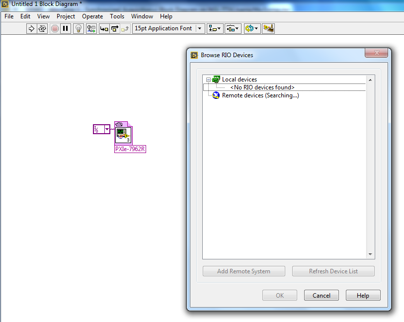
Target visible FPGA in MAX but not in LabVIEW
Hey!
I recently installed a RIO device. Before installing the equipment, I installed the module FPGA & RIO 3.0 as directed. Now, I can see the device in a position & automation explorer, but its not in list "Add target & devices. It says "No device found" in the existing devices tab. I don't understand the problem. :/
Add the target under 'my computer '.
Christian
-
File from an executable of LabVIEW PDM
Hey, I am writing a program that measures a bunch of stuff and saves to a TDMS file (as it is by far the easiest method and fast, I found). I was wondering, once that my program is converted into an executable, files are still viewable TDMS in Excel/OpenOffice, or viewing requires NI Diadem. Computers, on which the executables will run will not necessarily installed LabVIEW.
I would like to try myself, but let us, I am not worthy of a developers license...
Thanks in advance
Doug"are the PDM lines visible in Excel/OpenOffice?
Yes! the format of a file *. TDMS files do not change between the development environment and an application built.
That being said, the imported PDM of addon for Excel automatically installs with the LabVIEW development system and may not already be on target when you deploy your executable. Do not fear however! the addon TDMS for Excel is FREE and available for download here
-
In the example LabVIEW Full featured, which makes the entry point button reappear?
My question is this: what piece of LV code or invoke the node for the TS engine makes the entry Point button reappear when loading a file of sequence?
Background:
I inherited a modified version of Full Featured LabVIEW UI, which has been moderately modified (enough so this restart is not really an option, but it is still quite similar to use as comparisons for behaviors). In addition, this code was started in LV2012/TS2012 and I'm migrating to LV2013/TS2013, but this behavior is consistent in both versions.
Here is what I tried:
I have found that when the command connect runs (see attachment), the button which is a TSUI. IButton control, SEAO is grayed out or hidden. In the unmodified example user interface provided with TestStand, button is again displayed when loading a file of sequence. The problem is that when I load a movie file in my code and click it before the race, the button does not reappear. In my code, I can run the sequence successfully by right click on the movie file and selecting run, so I don't think the sequence has an error, or the process model.Thanks in advance,
Seth
Seth,
The entry 'options' of the ConnectCommand function controls this. On help page for this entry, you can see that there are options for "ignore enable" and "ignore visible." Or any of them may affect the functionality of the key entry point. You could try to make the options for both keys 0 and see if that fixes the problem. If this isn't the case, please let us know.
-
How to make non-visible control on the Front Panel appear at Design time?
I have a few controls on the front whose visibility is changed (on or off) at run time. The problem is that if I stop the Run time, the visibility of the control remains in the running in design mode state. So I am not able to see or find the control to make changes in design mode.
How can I make all the visible front-panel controls, or find and make it visible to a control on the front whose visibility has False?
Thank you.
It is documented in the help of LabVIEW.
Hidden front panel display
Perform the following steps to display a hidden front control or indicator. You can also hide the indicators and controls on the front panel.
- Find the terminal block schema for the object. "If you have multiple devices with the same type of data, right click on the terminals and select visible elements" Label in the context menu. Find the object with the label that corresponds to the object hidden façade.
- Right-click in the Terminal, and then select Show Control context menu if the object is a control or indicator to show if the object is an indicator.
You can also use the Visible property to display the controls and indicators by program.
You can also view all hidden front panel controls and indicators.
Path: Fundamentals-> build the façade-> how-to--> configure the objects-> display on front panel of the façade hidden object.
-
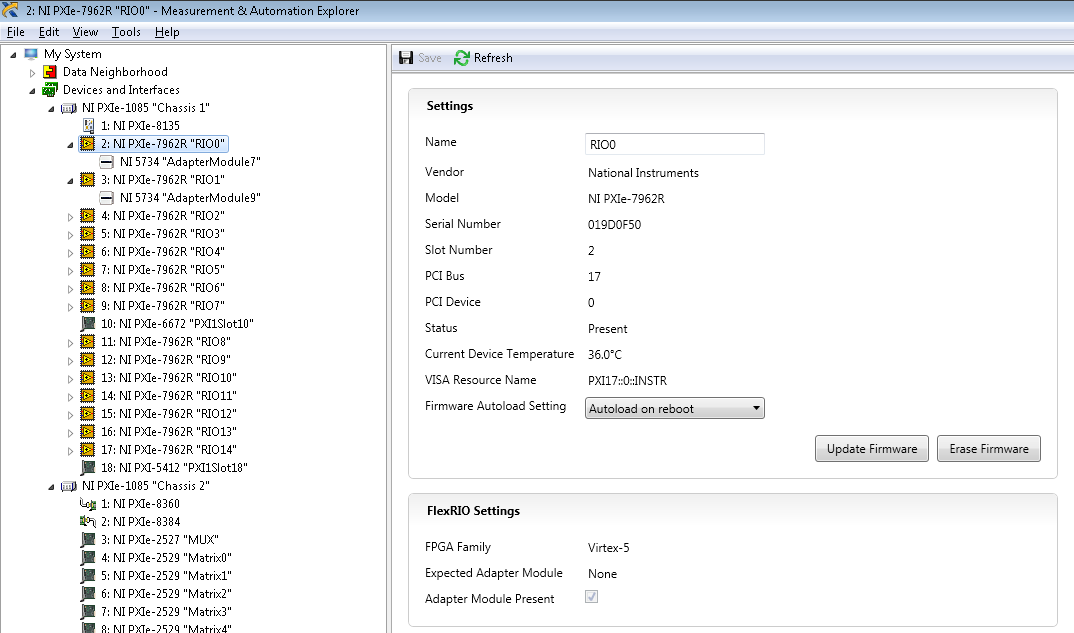
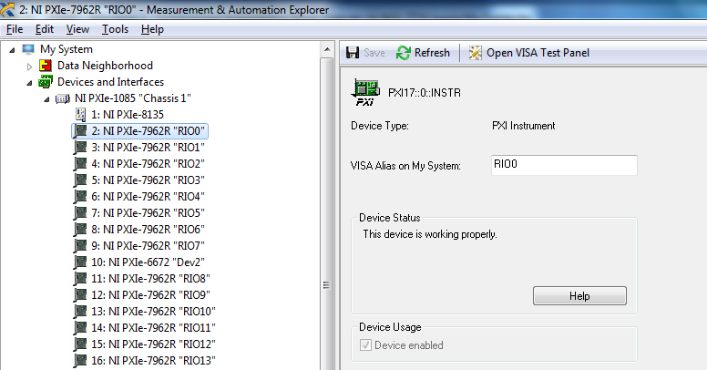
Unable to access SMU-7962R + OR-5734 in LabVIEW
Hello
I have already developed a SMU system that uses FlexRIO. This has worked well. FlexRIO devices appear in MAX OR as follows (note that FlexRIO modules have yellow icons of FPGA, and their adaptation modules are shown):
I'm now trying to build an exact copy of this system. I put together a together identical material, and (far as I can tell) I installed all the same components as the original system (using the NI Developer Suite 2015 DS1 set). However, something is not quite right. Here's what MAX OR shows me in the new system (note that FlexRIO devices now have generic grey icons instead of yellow icons of FPGA, and adaptation modules are not visible).
In addition, the LabVIEW code that I developed for the original system generates a runtime on the new system error "NOR-RIO: (Hex 0xFFFF0928) the name of the supplied resource is not valid in a resource name of RIO or the device was not found." Use MAX to find resources appropriate for the expected device name. " LabVIEW is unable to find RIO devices:
Here is the list of software installed on the new system:
I also installed NI FlexRIO Adapter Module Support 14.1.0 (who does not appear in NI MAX). Can anyone place what Miss me?
Thanks in advance!
Hi David,
2 controllers had exactly the same BIOS (version 1.2.0f0), which was the latest version for the SMU-8135.
It turns out that, even if I had installed the drivers, Windows had not "registered" (?) the drivers properly for some reason any. There was a lot of articles in "Device Manager"-> "devices OR-RIO":
- x 15 "NI SMU-7962R", were all OK
- x 15 "NOR-RIO FPGA Device", all had yellow exclamation on them.
I clicked "NOR-RIO FPGA Device" and selected "update driver software...". '-> 'Browse my computer for driver software'-> "Let Me pick from a list of drivers on my computer"-> 'NI - RIO FPGA Device'. After that I did "device of FPGA OR-RIO", all 15 exclamation points disappeared and I could use my FlexRIOs correctly.
-
Hello
I create a program in LabView in a program already developed in c# that uses ActiveX to control a laser machine.
The first thing I see in the program is the initialization of the ActiveX Server and equipment system:
Laser = new LaserAxApp();
LaserSystem = Laser.System;
I found a refNum in labview with LaserAxApp, but in their properties, I found systems within the ILaserAxApp property. But also, I found a different refNum called laserengineLib.ISystem which is another reference to class as AxApp.
which choose to continue implementing my program of c#?
Thanks in advance,
Stavrosyt wrote:
Hello
I create a program in LabView in a program already developed in c# that uses ActiveX to control a laser machine.
The first thing I see in the program is the initialization of the ActiveX Server and equipment system:
Laser = new LaserAxApp();
LaserSystem = Laser.System;
I found a refNum in labview with LaserAxApp, but in their properties, I found systems within the ILaserAxApp property. But also, I found a different refNum called laserengineLib.ISystem which is another reference to class as AxApp.
which choose to continue implementing my program of c#?
Thanks in advance,
Thanks anyway... I managed to find the answer.
It works with the properties and methods in the ActiveX menu in Labview. To answer my own question, the result is to use iLaseraxapp and ilasersystem refnums.
Here is better explained:
(1) start the laser with refnum laserengineLib.ILaserAxApp
(2) use the open automation to open and
(3) bind it with a node of the system IlaserAxApp (true visible) property.
And that's all. Then you can use lib system even for event reminder reg and ilaserdoc for loading a file of xlp laser.
-
The trio of Labview, card PT and Basler A - 610 camera F gray
Hi all
I'm doing a project on the merger of the camera with a PH d teacher. As I am the research assistant I can make all preliminary ups. in any case its very annoying that I'm stuck on the first step. Which is simply the video detection from one camera on LabVIEW. The equipment I use is an A-610f "basler" firewire camera, a gray PT 1394b PCI Express Card (http://www.ptgrey.com/products/firepro/index.asp).
The basler connects with gray map of PT via a firewire cable. Now that the card is not an OR product it is not shown in the MAX I just need to get the video of LabVIEW, but I don't know where I have to access the camera from.
I'm using LabVIEW 8.2.1 and I Vision Assistant and Toolkit Vision and Motion installed on my machine. In addition I just download demo version of the Vision Development module as well. Again for the clarification that I just need to acquire video from my camera.
Finally ive it resolved myself!...
 .. The main problem was with the son of the late himself! .. I was amazed when gray pt was charging me $75 for a firewire cable because it was available in my country of origin for Rs 250 to the free market. I bought one and then started five days of immense struggle and re struggle. Finally, I thought that ive tried all means why not give it a last try and buy the original cable. I borrowed it from a firm surface and 'khatttaaaaaaak'... it works! Although I had to install the SDK of basler to view the video stream. Once the entrance to the camera was visible on the SDK. It was smooth then leave. IMAQ Max was able to detect the camera. The right software was all that remained to be installed. Once the right software has been installed using MAX. It was all great. The power of the camera was visible on max as well. I opened the Vision Assistant and he began to take the camera feed as well.
I decided to transfer to another device in the PCI card and hooked to another quality firewire cable. The repeatition of above process ensures that the camera is fed was visible on SDK, MAX and Vision Assistant. Although permitted high-speed bandwidth continues to be a problem. Another problem which forced me to bite the nail outlet there is over and done.
Moral of the story: use the original substance

-
Make controls/indicators in all the tabs display updated even if not visible?
I have a Labview VI simple enough that I need to run in a loop of 10 ms. Currently, I can't get it runs at 17 m, there a RS422 with send and receive a message each 10 m I have a lot of troubleshooting indicators on a Debug tab. I wonder if these indicators are updated even if they are not on the currently displayed tab. If so, changing the property node 'visible' to all of these indicators will speed up execution?
Thank you
Well, there are other things, like putting your reading of the RS-422 in another loop or passed the data read in the transformation of producer/consumer . Without seeing the actual code, it is difficult to give advice more.
Maybe you are looking for
-
Issue adding arrow/highlights in 10.1.2 iMovie
Hello. I edited together a set of volleyball clips in iMovie version 10.1.2. Try adding an arrow highlighting of my daughter. I have created a freeze frame of the clip where I want to put the arrow, the arrow as a .png, you drag the arrow on my clip,
-
I create a movie using Windows Movie maker file. Changes do not appear in the final WMV file. But it is in the MSWMM file. How to fix this?
-
the Player Windows media share
I can't get my Media Player to share files on my TV. Any thoughts?
-
Where is the USB port on my new HP Pavilion 6735a?
I just installed and that you now want to copy all my files stored on USB? But where is it? Surely I don't have to pull out the office and go to the back of the conputer whenever I want to save something on memory stick?
-
How to return data using the object type?
Hello all - I have an obligation to return the values object type.In the same way aslist - Plan1, Subplan1, Fund1, 2 Fund Fund 3list - Plan2, Subplan2, Fund2list - plane3, Subplan3, not fundsTo achieve this I wrote below proc but its giving as respon