6008 NI DAQ issues of reading pressure transducer
Hello everyone, I am a new user of labeled and not one expert on electronics, so please bear with me.
I'm trying to read a signal 4-20 my by a pressure transducer using a NI DAQ 6008 and Labview version 8.6. I am running Windows XP Professional. I'm the transducer, (http://www.omega.com/Pressure/pdf/PX01-I.pdf) providing a voltage of 10 v I have a 235 external resistance ohms between the terminals positive and negative data acquisition (although I am not sure that it is correct). At the start of my VI, I am able to measure a voltage of environ.9 data acquisition (verified by a voltmeter/ammeter) V and a current of environ.39 my.
My problem is the fact that when I have a supply pressure of my sensor, I have not received any signal whatsoever by the transducer, despite the fact that it is important that the pressure should give me a signal. Is this a problem with my installation, connections, data acquisition (which has been reset in MAX number of times and pass the self-test) or the sensor itself?
Thank you for your time and consideration
Hi prenerk,
You are right that resistance must be connected to the terminals positive and negative a way to HAVE to create a measured voltage to current. Here are two troubleshooting steps you can try:
1. check with an ammeter so you are detecting a change in the current when you apply pressure to the transducer.
2. open the Explorer Measurement & Automation and use a Test Panel to measure the voltage of the device. This will ensure that there is a mistake in your LabVIEW code. Also check the MAX pinout diagram to see if your sons are correctly plugged into the channel of GOT it.
If you have not discovered a problem with the above steps, we will have to learn more about your sensor pressure and how you connect it to the 6008. We will need the information on the sons of the Omega instrument and how they are connected to the excitation voltage source and 6008. Let us know how it goes!
Brian
Tags: NI Hardware
Similar Questions
-
How to wire a pressure transducer loop 2 wires for the NI 9949 RJ - 50
I am new to the NC and data record.
I want to connect a 4/20mA, pressure sensor loop 2 son of a Terminal screw OR 9949 RJ - 50... that will then connect to an entrance NI 9237 module.
The NI 9237 module is installed in a chassis OR compact 9174 DAQ.
I shall be measure the pressures of air brakes truck to compressed air system of zero kPa (gauge pressure) up to allowance of 1000 kPa (gauge pressure).
The 2 wires on the transducer are identified as: food + and + signal
I would appreciate it please advice on the appropriate terminals on the NI 9949 RJ - 50
Unfortunately, it seems that you have the wrong module for this task. The 9237 is used to measure the production of bridge-based sensors (for example, a strain gauge). Signals that it is supposed to measure are fundamentally different from the 4-20mA signal pressure transducer outings.
Take a look at the NI 9203, 9207 or 9208. All have at least a few channels designed to take a current 4-20mA input. Then, give the team nor a (877-387-0015) call to talk through your application and make sure that you select the right equipment for what you want to do.
-
Hello
Does anyone have a pressure transducer with offset null simple vi constructed in code. I'm relatively new to labview and most of the examples I have seen are way to complex for me to understand what is happening. Is it better to use the DAQmx Wizard or data acquisition? I have two sensor of pressure (excitation omegadyne-10V) hung on to with a module for 1121 SCXI-1327. I wrote a program to convert mV to pressure using a linear scale, but that's all I know how to do at this point! And I want to know how to read the two transducers. Thank you!
Don't forget that you will need to change your excitement of inside out and remove the part with the shunt calibration.
-
Hello
I am completely new to LABVIEW software.
I learn a LABVIEW code existing my pressure (attached) acquisition system which has the path of data as follows: pressure transducer Validyne--> Validyne CD280 - Dual--> SCB - 68--> PCI - 6024E--> LABVIEW and I have a few question:
1. How does the complete system of the transducer to the LABVIEW work? That is, if we apply the pressure of the transducer, it will change the resistance of the probe then...?
2. How can I find the equation that expresses the relationship between the pressure and the tension to the keys of the Validyne double-CD280 in the LABVIEW?
3. If I want to do the probe calibration, what are steps?
Thank you
You did not include most of the subVIs.
-
I received an omega pressure sensor (model px309) with only three wires: Red (power supply +); Black (power supply)-; and white for the signal.
Should the output voltages of 0 to 5 and a voltage range from 9 to 30. It measures gage pressure.
I use a power supply that can output 12v to provide power to transduce and a Ni-9205 to collect the signal.
Red and black were connected to the power supply. The white one was hooked up to the ACH0 to collect the signal. In the test diifferential model, I used a wire to coneect to COM. ACH8 Also, I plugged the black wire pressure transduce to COM.
Is this the right settings?
I run my program and I found that the signal is not continuous, and it has a Variant. Please see attached picture.
Is this normal?
Hi Kang,
Depending on what beach you go the DAQmx task for the 9205, looks like expected behavior.
It seems that noise you see is on .1mV, which is quite close the specification of random noise for the NI 9205 module:http://www.ni.com/pdf/manuals/374188d.pdf#page=22
If you select a range of 0-5 v for example, DAQmx will put the module mode +-5V, which corresponds to a 116 uVrms noise, that seems pretty close to what you see.
-
Design practice nor 6008 USB DAQ
Hello
I have a few question, I'd like to introduce. I need some sort of indication on how to better perform a timed cycle of acquisition driven by WSF.
I'll send my VI (conceptual, not one currently working one) and ask for explanations.
The goalI need to acquire a battery voltage. Load current consumption is driven by a couple of transistor. I drive the hollow transistors two digital i/o for USB data acquisition.
Because I need to have a power for a given time cycle, I need to have some sort of time control on the output.
So I wrote a simple state machine whose States are updated when a timer reaches zero. Each State has its own queue time.
Moreover, I differentiate between acquisition and control operations using two all in cycles.
First question: is this a correct way to a timed WSF of construction?and now:
The problem (s):
I need to connect and establish a correlation between the input line for the internal of the fsm States. So I madesome digital indicator on the face before of the VI and created a local variable (I know that local variables are BAD, but I had no other idea everything) to pass values for some time to the other.
I also want to select State sequent of the FMS based on the input value, I get a channel. I can stil use a local variable?
Are the two related tasks?
Second question: are local variables, something that I can use for this task?
Last but not least: I need to filter on the values.
In this vi I perform a filtering operation and then I get the I use for control of local variables.will be this filtering desync the two cycles while? will I run out of control before running the filtering?
The same question is valid for the purposes of registration: the unfiltered data record, I guess is unnecessary. But based on this 'architecture' I know the country reports and the recorded signals are out of sync (as happens in many game data acquired with this vi).
Is this a problem of logging (perhaps given by different buffers for data acquisition and internal State or something similar) or the whole WSF will be out of sync, then all acquired data is more useful because it is out of sync?Any advice would be much appreciated.
Best regards
Luca.
Luca,
Question 1: This is a reasonable start but need some things to make it a good WSF. There is no waiting or delay in the loop so it will run as fast as possible. U.S.-6008 outputs digital software timed so that the DAQ Assistant can take a long time, but the amount of time is unknown and not necessarily consistent from iteration to iteration. Since the DAQ Assistant Analog Input in the other races of loop to<= 10="" iterations="" per="" second,="" a="" wait="" of="" 100="" ms="" in="" the="" fsm="" loop="" seems="" like="" a="" good="" starting="" point.="" waiting="" 3000="" ms="" is="" not="" a="" good="" idea="" because="" the="" loop="" becomes="" unresponsive="" to="" the="" stop="" button="" for="" long="">
Do you need to write on the lines on each iteration, even when the data has not changed? Add a write state that is called only when the data changes.
The DAQ Assistant has a Stop input and an output of Stopped. When you are ready to stop the loop, the stop signal must be wired to these inputs so that the DAQ Assistant can delete tasks. The output of the order can be connected to a Terminal to stop the loop.
Problem (s):
It seems that you want to link the two loops. Local variables are usually a bad way to do it. The best way is to use queues. A queue can send the current state of the file loop. (More comments later if that's really what you need). Another line can send data, or better, the commands, the loop of the file to the loop.
I think you want digital output values rather than the State. Especially if you add a State writing as I suggested above, the current state will not always represent the condition of the power of your test. To make this work with the additional state Boolean matrix must be moved from one iteration to another via a shift register.
It seems that you have at least two controls to be sent from the loop of the file to the loop. One is the stop command. The other went to the higher power level control. You should probably have a command to set off power level which can be used if the battery voltage becomes too low and before stopping. How your program is currently configured, the last level of power will continue as long as the power of the computer is on and the USB-6008 is always plugged. The cessation program does NOT reset the lines.
When you use anti-parallel to the queues, you must be careful on the definition of wait times and the timed out case management.
The benefits of the queues are that it is easy to ensure synchronization at the level you need, the data can be stored according to the needs, and there are good examples. It also avoids the possibilities of race conditions, often introduced by local variables. This program could be based on a variation of the design producer/consumer model.
Filter questions: any filter introduces a time delay. In your case when you filter 100 samples 10 times per second, it is likely that the filter will do well until the next data set has arrived. The delay of the filter is not affecting your synchronization. The above lines will solve problems. Since you are looking at time of cycle seconds and the minimum interval on the order of 100 ms, the exact chronology (to tens of milliseconds level) is probably not too important.
The real question about filtering boils down to this: does the control work better if the signal is filtered?
- - - - -
I'd probably all this a little differently. Given the slow speeds and the small amount of data, a simple loop with an improved state machine is all that is needed. Get rid of the DAQ Assistant and learn how to use DAQmx screws. States could include: Init THE Init, Init File, Idle, read, write, DO, Analyze, filter, adjust the power, wait, Save, close file, DO, AI Shutdown Shutdown, error and exit. No variables. No indicator fake just to allow the creation of local variables. Very little code outside the structure State case. None of the queues.
Lynn
-
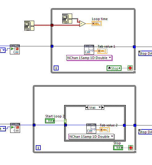
How can I make DAQ ECU MC read.vi and MC Download.vi exucute in parallel?
Hello everyone,
I have a question about MC read DAQ vi and vi MC Download.
I need to read data from two different interfaces CAN with the acquisition of data MC read vi (in polling mode), so I create two loops in parallel. Theo, two loop should be runing at the same time. But after the experience, time to loop 1 double exucution when I activated the loop 2. This means that something inside keeps it's runing at the same time.
It is that this vi is protected by password, so I can not open its schema.
Is there anyone knows what keeps it runing at the same time? Or how to open its diagram?
Kind regards
Cheng
It's the opening diagram will not help. In this case the VI is already set to reentrant (pre allocate) to call the Sub - VI is not the call blocking, two parallel loops will go at the same time the Subvi. The problem is that in this sub - VI it is a call to the DLL to the niemclv.dll DLL installed in the System32 folder. This is the DLL that does all the heavy lifting for the box tool of playback functions. If the runtime really double as you say, then this DLL is not configured to have multiple calls at the same time towards her, and that's what this block of work. There is nothing that can be done to remedy this short OR releases a new version of the Toolbox in support.
I'm not a fan of these limitations toolkit, when they are basically a software layer more, that's why I made an idea about theExchange of ideas to make this Toolkit (and another can be) written in g pure, so that such problems can be fixed by the developer.
-
To measure the pressure using a pressure transducer that provides the analog current output 4mA-20mA
I wanted to acquire the current analog signal which varies from 4-20mA using NI 9207. I tried in 2 ways.
method 1 - created an input channel current analog & used a reading Vi to acquire it. How can I give the channel connections in this...
method 2 - using NOR-DAQ Assistant, I put the channel connections and I got Amplitude versus time graph. She also gave negative values. Can I do this way which is easier? How can I solve the problem
First attachment belongs to the 1st method
Second attachment belongs to the 2nd method
-
How to wire NI 9203 to Emerson PT5 pressure transducer
Hi all
I started studying with 9188 OR cDAQ and analog input NI 9203 module. I'm really new on the DAQ hardware and I confused about my wiring for the NI 9203 pressure sensors. I want to use 6 pressure transducers whose output signals are ampere (4-20 my). In the manual operation of NI9203 shows that there is only 1 negative port (COM). Could I wire 1 more NI 9203 pressure sensors? If it is possible, how would I do that? The pressure transducers that I wanted to use a 2-wire and its technical specifications is Emerson PT5.
Hello
You should be able to branch out of the output of the power supply 24 VDC 8 drivers. Does that help?
-Carisa
-
Pressure transducer USB-6211 noise error
Hi all
I tried to connect a pressure sensor through my data acquisition by the voltage reading and when you use a multimeter to check the voltage measured by the son, I get exactly what I want, but when I look at reading through labview, I make so much noise that I can not even acquire a strong enough reading for the tests. When to play with filters and blocks measure, I'm sure that some of the ways to reduce the noise and get the reading of the amplitude of crete would, just do not know where to go next, as I have tried so many options like this already.
Problem has been resolved. Simply a problem of ground that I threw.
-
How to get mydaq recognize px309 pressure transducer % 3F
It has only 3 wires instead of the usual 4. They are black, red and white and negative excitement, positive excitement and signal respectively. I plugged the black wires and red to an external power supply, the white wire to the myDAQ HAVE. Then I went to labview, opened DQA assisntant - acquisition - tension - ai1. Then I put samples of continuous get ot and drew a graphical indicator and press the run button. Yet, the only signal I get is noise and graph (amplitude time vs) shows no change when pressure is applied.
Have you tried also runs the black wire from the transducer into one of the analog grounds on your MyDAQ? Measures data acquisition potential, without reference to ground the unit will not be able to measure anything.
You can also use an output on the analog MyDAQ to produce the voltage instead of using an external power supply.
I hope this helps.
-Nick-
-
Using DAQ Assistant to read voltage of 9205
I am new Nock in it and I tried to read the voltage level of 9205 relating to 9172. I use it in XP mode virtual because windows 7 does not have labview 8,9. I installed the drivers for data acquisition.
When I check the meter in automation and Explorer, it works very well which means it reads im DC voltage supply. When I created a VI facilitate data acquisition, I chose the right channel, the entry as analog voltage, the numeirc indicator shows it is-10 to 10. I noticed he did the same thing, even once the USB is disconnected, which means that the function helps daq was not save the data of the 9205.
Can someone help me?
Hi aaclabview,
The way in which you have added the device to MAX makes the device act as a simulated instrument. Simulated instruments only generate sine wave data to test a piece of code without using any material. A simulated device has the icon yellow as shown in the screenshot you provided and are completely dissociated from any material, so add or remove the usb device has no effect.
The problem with the help of Windows XP mode as mentioned in the above KB is the USB transfer must be enabled for the measurement and Automation Explorer inside the Virtual Machine detect the device. Using the unit in this way is not supported or recommended by National Instruments and can lead to instability and the latency of the errors in the acquisition of data even if a connection is established.
It is a more sure bet to try and install LabVIEW and hardware drivers DAQ as described above on the real Windows 7 machine to try and run inside the XP mode.
-
Another type of MTP issue I read here
need information: Sansa Fuze 4 GB version 02.03.31A using the MTP, info PC mode: build self system, XP home SP3, WMP 11. CPU AMD FX 60 2.6 Ghz, 3 GB, ATI gfx card ram
Problem: The mode MTP and WMP 11 worked fine several weeks ago. As sync playlists, load mode MTP, PC also detected in MSC mode. No problems.
Recently, when I plug the Fuze MPT mode, I found new hardware balloon "sanza fuze" then it turns into MTP device then he said: ' your material has been blocked, but you must restart the pc or it may not work properly.
So I reboot (the made with rocket plugged upward in and out in MTP mode) I get the new ball of material found again. I check the Device Manager and see the "rocket" listed in portable devices, then renamed it to MTP device.
To end up with one brand yellow when he tells me to restart the pc. If I check the properties at this point, there is a code 31 "windows cannot install device because you have to restart the pc.
Reboot, even sung and danced. Windows still detects of Fuze in MSC mode, very well. WMP 11 never know same here if in MTP mode (because never really settle the rocket)
How to complete the restart installation I guess that could be the main issue, then I expect WMP to pick it up.
What I tried: after reading these fourms and searching the Web I have:
1 reinstalled WMP 11 (does not solve the issues)
2 installed microsoft MTP Kit (does not solve the issues) portage
3 hook of rocket for a Pc HP using the same cable and WMP 11 picked up very much like "Sansa Fuze 4 GB" and installation of synchronization begins.
4 formatted fuze and tried on my PC (does not solve the issues)
5 Ran win xp SFC (System File Checker) to start / run / guest. (took about 25 minutes) always the same questions.
6. system restore to a few days ago. (does not solve the issues)
7. probably some other things I've forgotten and the list above is not necessarily in the exact order.
I read about the monkey thing and some on Winamp, but I really want it works as it should just like he did on the machine with WMP 11 HP, just as he has done on this pc a few weeks ago.
Which might be of importance: got in trouble with the old creative soud card and had to try to remove completely. still an unwanted software here I don't know, but I got most of it.
Went from xp SP2 SP3 and a lot of updates to Ms.
can't think of anything else, sorry to be so long, just that you stay up to date on the situation.
Thank you
Mark
OK Tom, I'll give it a try and post back with the results.
Thanks for the find
-
As part of our product documentation, I would like to ask for some information on Adobe Reader 7.0.7 we used.
Could someone give me a list of the issues/problems known at the time of the release and the problems discovered since version?
I doubt it very much. Since Adobe have corrected and revised several times in Reader 8, 9, 10, 11, and DC.
You can report that it is obsolete, unsupported, end of life and he will surely understand unfixed security vulnerabilities.
-
Issues of reading media in Satellite L650-11F
Hello everyone
Since I got this computer (for about six months now) I had a problem to play media, movies to music just, some time during the game, it has some delays, I put t know how to explain it, it s usually only 5, 10 seconds max, like his movement, sounds and images. It is only once and it does not yet. I used all the players, that you can imagine, all the codec packs, and yet whenever I play a movie, it made every time, only once.
Do you know what it could be?
Thanks in advance
Hello
What operating system do you use?
It is not easy to understand your problem, but try it please watch movies with VLC media player.
This player is really good and can read all formats.
Maybe you are looking for
-
How to disable the screen saver when you watch videos in full screen in firefox?
This only happens with Firefox, other browsers videos play normally and without interruption. I want to keep my window screen saver by default but not when watching full-screen mode.
-
Why should Firefox permission to "discover known accounts" on a phone?
This authorization is not covered on the Firefox Android privacy policy.Thank you.
-
problem of re - install iTunes
Computer was wiped clean, I reinstalled all my itunes re-installed software. I can access my library and everything seems fine with that. When I tried to login to buy something, it tells me that my id does not exist. I created a 'new account' to t
-
Start before logon functionality
Hi all I have a customer who wants to start before Anyconnect VPN connection. I can't find anything on the user experience. Is it possible to make the process transparent to the end user so that they only connect once to Windows and it will take thes
-
I use Photo Mechanic with Lightroom 4. I was asked to re - install Lightroom. I have a disc for LR3. How should I proceed?