6341 USB versus 6215
I used a USB 6215 OK. It was working fine. However I had to controll my valves of hardware I/O. I just installed the new USB-6341. I'm just 1 line of control at a time. I'm currently sending a binary or hexadecimal value to control the valve. It is not in the same way as the acquisition of data USB 6215. Does anyone have a simple approach to control a bit at a time. I'm not yet familur with the acquisition of data USB 6341.
Philippe
Dennis Knutson says:
tbob wrote:
Put the write function before the start function. The write function simply writes data into buffers of DAQ card. The data does not get generated until the start function is called. So in your code, you were saying the DAQ write an empty buffer before you filled with data. Reverse the order and see if it works.
Sorry, put the task to start first is normal. Just look at one simple examples like writing a Chan to dig.
Normal, perhaps, but not always the case. Look at the example called write dig Chan-Ext CLK. He was writing before departure. I guess it works both ways. I always put the writing before departure because I sometimes used external triggers. Which lead me to believe that he must write in the buffer before starting the task. I do the same with analog outputs also.
Tags: NI Software
Similar Questions
-
using 6341 USB frequency generation device but level is droped when conect
I use the DAQ USB-6341 material for frequency generation. The desired frequency is generated correctly but when I connect to any other device, the voltage level, I mean that the peak to peak of the frequency voltage has dropped to 0.6, 1 Volt and also the frequency has varied. I unplug the charge or unit frequency becomes constant and peak-to-peak voltage becomes 5.
Please some help me solve my problem.
Thank you
Best regards
Naseeb
-
Computer does not start when connected to USB-6341
Hello
When my board 6341-USB is connected to my computer and the device is on, if I start the computer the USB-6341 module, the computer crashes before windows starts.
I said that the computer is an HP with Windows 7 64 bit computer. All Boot on USB configuration are disabled.
Is it possible to start the USB-6341 before the computer or not?
Best regards
CFOE
Hello
Unfortunately with my HP computer, because the HP hardware, the computer cannot be started if USB-6341 is connected and powered.
Best regards
CFOE
-
Hi all
6341 USB only generates a 5V DC signal. It works of NI USB-6009, but not of 6341. IM choosing AO, 0, 1 sample (on request) and feed a constant 5 integer to him. With the help of pins 15 and 16 (AO0 and AO 0 GND)
Using Labview 2013 and DAQmx 9.7.5
Help please!
Have you tried to use the test panel in MAX? It is a good starting point. The other thing is to try other analog output channels to see if none of them work.
It could also be that your 6341 does not keep the value that you are out once the program ends. You have just a DAQ support to write a single point, then your program ends. Try to test the panels in MAX and see if you can monitor the AO line like that.
You can also try an example of shipping from the example Finder (help > find examples). I recommend watching analog voltage - on application exit.
-
Amnesty International and counter sync + USB signal stream (USB-6210 vs USB-6341)
Hi all
I'm at a stage of identification of a material suitable for the following tasks:
- 5 analog inputs (AIs) of reading at the same time, tensions at a rate of kSps (at least) 10,
- application captures 2 inputs using timers (detection of contours with timestamps), square wave entry with duty ratio of 50 percent and about 1.5 kHz frequency and variable pulse width / frequency (from 2 sensors hall, representative of the DC motor rotation speed and direction, quadrature signals), resolution of timestamps should be (at least) 50 ns,
- AIs and counters should behave in a deterministic way, and must be synchronized in a way,
- data to be transferred via the USB port of a host computer with Matlab Data Acquisition Toolbox (unfortunately not LabVIEW).
I've identified the long USB-6210 USB-6341 and potential candidates of material to accomplish the above tasks, but after reviewing several documentation and the topics of the forum, I'm still a bit confused, if both are fully working and my approach described below is not working properly.
Counters: I intend to use the internal time base available 20 MHz as being the source of meter to get into account the resolution of timestamp 50 ns. External impulses hall are used as sample clock (about 1.5 kHz, see above). As the pulse width varies, the sample clock is not constant.
AIs: Using a 10 kHz internal clock signal derived from the time base of 20 MHz for timing and analog inputs (trigger) start-up and counters simultaneously material should translate into the required synchronization and deterministic behavior.
It work? Other recommendations?
Next is the USB data transfer: all HAVE 5 and 2 data entry of the meter must be correctly transferred to the host computer (the corresponding rates are shown above). USB-6210 is capable of 4 USB signal flow, device USB X range (6341) offers 8 of them. Unfortunately, I could not understand the exact meaning of the expression "signal flow" still. Do I need 1 flow of input signals (would be 7 for my application described) or 1 stream for all analog inputs and 1 for counter inputs (lead 2 streams for my request). Is there no further details on this approach (more than Streaming of signals of NOR) USB signal flow?
Any challenge to the described application that I might have forgotten? 6210 USB seems to a very limited number of entry PFI, maybe even too low for my meter participate application?
Looking forward to your comments and advice.
Concerning
jAwA
1. I recommend the X-6341 series on the M-series 6210 sake of counters/timers. It is more of them, and each of them is more capable. It can also have a great FIFO embarked for meters that may be important in certain tasks, although I don't think that you currently deal with one of them.
2. your general concepts on timing & sync are satisfactory. You will be able to share and to route signals that help ensure synchronization and determinism between the timestamps for your various tasks. Note that for meter entry tasks, you need set up the trigger 'Arm Start' rather than the regular start trigger.
3 is not authoritarian, but I believe that the flow of signal # will correspond to the tasks #. For you, it would be 1 task of HAVE and tasks CI 1 or 2. (Not clear if you have 1 Encoder with 2-channel quad that would require 1 task of CI, or if you have 2 encoders with 4-way quad).
4. pay attention to the hall effect signals that are not virgins. Digital filtering is available and probably better on the X-series, the series M.
5. strictly speaking, edge detection is a type of digital input task that produces samples but no timestamps. Ideally, I would like to parallel wires on the two digital inputs for the entries of detection and counter change to position quadrature decoding. Then I would sample the counters Encoder 1 or 2 using the internal pulse 'event of detection of change '. I would create another counter timestamp change detects pulses as well.
-Kevin P
-
problem with / s digital correlated on USB-6341
I'm testing an application that fact/s digital correlated, written in C++ with a USB-6341. I use NEITHER-DAQmx version 16.0.0f0.
Because this application will be used by people with a variety of different DAQ hardware, I tried to write it to manage a lot of contingencies. Then when I put in place a DIO task correlated for the release, I'm trying to determine the width of the channel:
uInt32 dataBytes;
If (NIerror = DAQmxGetWriteRawDataWidth (h, & dataBytes))
On my USB-6341 dataBytes returns 1, so I try to write data using DAQmxWriteDigitalU8(), but which returns an error saying:
device USB6341:-200565: specified the digital channel contains more bits than supported by the 8-bit version of DAQmx Port write.
Use the version of DAQmx Port write who takes in charge the broader digital ports.
If I remove the test and force it to use DAQmxWriteDigitalU32(), then it works.
I'm afraid that if I try to always use DAQmxWriteDigitalU32() I may be wrong with other devices that do not support 32-bit channels.
Is this a bug in NOR-DAQmx associated with USB-6341? Have I misunderstood something about how it works?
John,
It seems that it is a known issue with DAQmx and a corrective action request was filed for this problem. For now, using the DAQmxWriteDigitalU32 should work fine if the device has ports 8-bit or 32-bit.
-
Audio measurement with the USB NI 6341
Hi, I tried to find a forum, but has not found an answer to my topic.
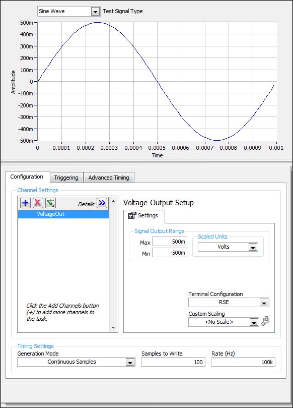
I have an usb-6341 or data acquisition. in our project, I want to generate 1 kHz sine waves go AO0 and inject our test module and the output
I want to measure the output signal of AI1.
in the NI MAX tasks Panel, I made this settings
If I understand correctly to produce the output signal of 1 kHz I put samples to write = 100 and a frequency of 100K?
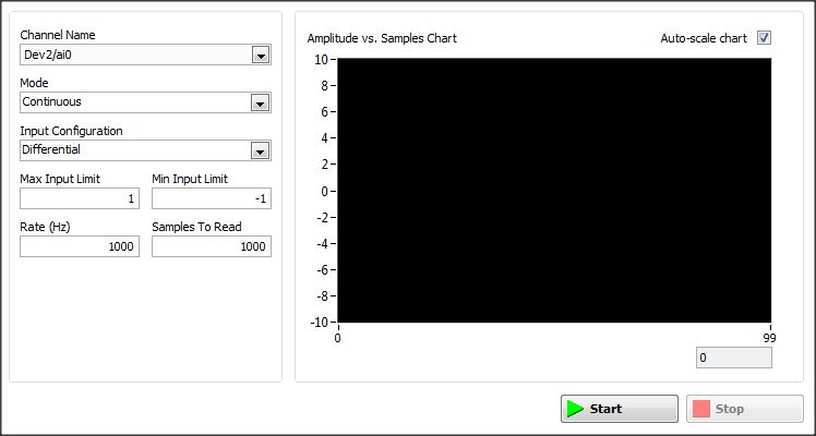
But what settings I need to set in the window of analog input
Thanks for a response
Hi Arbo,
the configuration depends on what type of signal you would expect.
If it will be similar (frequency & amplitude) that generated, then configure the same as AI. One thing you should pay attention to, is to choose an appropriate Terminal configuration (Diff, CSR, NRSE) - you can read about it here: http://www.ni.com/white-paper/3394/en/#toc4
-
USB-6341 not on the list of simulation devices
I want to create a USB-6341 siumulated, but this model is not in the list of available under devices simulated in MAX X series devices. I don't see in the devices of series X available for the simulation are PCIe devices. I have MAX 4.7, 9.1.5 DAQmx and LabVIEW 2010. I did this on other computers running older versions of the software and saw this device on the list, so there must be a software component that I have installed, but I can't understand what it is. Any suggestions?
Richard
Material of the series X USB were not released before DAQmx 9.2; you need at least this version in order to use a simulated.
-
Example of Code OR-DAQmx (C/C++) for playback of 8 differential analog inputs on USB-6215?
Are there examples using the API C/C++ of NOR-DAQmx in an application that illustrates how to read all 8 analog channels (differential) on a device USB-6215 or similar? I can find examples to read only one channel, but nothing for multiple channels. When I try to read all 8 channels, I get only entry on the first channel. Any help would be appreciated.
Kind regards
Bob
Brandon:
Thanks for the tips. I have it working now.
Kind regards
Bob
-
USB-6215 DI ReadMultisamplePortByte rate is only 2 kHz
I'm trying to use the USB-6215 for determine the speed and direction of a fan with two optical sensors. I use the following code in a .NET library to get 1000 samples of two lines and use the data when optical sensors are enabled to determine the speed and direction.
using (Task ctr0 = new Task())
{
  using (ctr0.DIChannels.CreateChannel("usb6215/port0/line1:2", "", ChannelLineGrouping.OneChannelForAllLines))
  {
    ctr0.Stream.Timeout = 500;
    DigitalSingleChannelReader dReader = new DigitalSingleChannelReader(ctr0.Stream);

    try
    {
      // Start the task
      ctr0.Start();
      byte[] results = dReader.ReadMultiSamplePortByte(1000);
      ctr0.Stop();
    }
    catch (DaqException e)
    {
      Console.WriteLine("DAQ Exception: " + e.Message);
    }
  }
}

// Analyze sample data and calculate speed/direction
//...
It seems to work fine, except for one thing: the samples seem to only take at 2 kHz. This means that to some rpm, the acquisition of data sometimes will lack one optical sensor being activated. According to the datasheet, the USB-6215 is a sampling frequency maximum of 250 kech. / s, and looking through some other threads, this rate is divided by the number of channels you are sampling (i.e., samples of two channels gives you a rate of 125 ksps / s for each channel). My question is, why my sample notes so low, and how can I taste at a faster rate?
Sheet indicates that the rate you quote is for the analog input. It clearly states that the digital I/o is a programmed software and you have the chance to see 2 kHz. The max with a timing of software is usually around 1 kHz.
-
Model generation with USB-6341?
Hi all
We have developed a software quasi multifunction 'device-independent '. This sw is capable of generating the sequence shot timed with the device really used. Up to now, we have used devices PCI-6025 and USB-6221, but now we bought a USB-6341 and when I try to use a message of 200565 error pops up: "specified digital channel contains more bits supported by the version 8 bits of the Port DAQmxBase write.» Use the version of DAQmxBase Port write who takes in charge the broader digital ports. Minimum size of write in bits: 32 "
I tried to change PORT0, PORT1 and PORT2 but only PORT0 is legal for the model generation process and it requires DAQmxWriteDigitalU32 function...
I don't understand why.a / 6341 contains 24 DIO lines
b / only 8 DIO lines are clocked by materialThen there are 24 DIO lines (i.e. 24-bit 32 no!), but only 8 lines are timed by the hardware and I want to use only this 8 lines for model generation!
Our whole software is based on 8-bit pattern-berries (writeArray type is "uInt8"). If we cannot use this structure, we must rewrite dozens of functions...So, how can we use the function of DAQmxWriteDigitalU8 with USB-6341 or what can we do?
Thank you
-George Cs.-
Dear George,
It is an interesting question, which may seem a bit unintuitive at first. The main reason for the 32-bit write operation (although the USB-6341 has only 24 DIOs) is that the functions and the driver support other devices too. As you can see in the manual of the unit (http://www.ni.com/pdf/manuals/370784d.pdf) X Renault series supports digital IOs up to 32 bidirectional signals.
To keep things consistent exploitation of 32 bits is required even if you use only a subset of the available ports.
I hope that this helps to explain.
Best regards
-
connect multiple signals card NI USB-6341
Hallo,
I'm trying to connect the signals of several NI USB-6341 map.
This map has 16 channels but not 32 pins available.
for example if I want to connect a signal on channel 0 I connect to pins 1 and 2 and for channel 8, I have to connect to channels 2 and 3.
If I connect only channels 0-7, it works but if I connect channel 8 I do not get the real value of this signal.
any ideas?
Thank you
Theodore
Theodore,
This sounds like it should work. Basically, you use AI0-3 and AI8 - 11 for your four differential signals. This leaves you AI4 - 7 and AI12-15 free for single operation is complete. The configuration of the terminal can be defined on each channel. To do this, you can use DAQmx create channel several times to add channels with a different configuration to your task. If you need details on it, let me know what environment you'll be programming, and I'll see if I can provide more specific assistance.
Hope that helps,
Dan
-
Measure the time of the rising edges of a digital stream using a USB-6341
I have a DAQ USB-6341 map.
I use Measurement Studio (writing code in c#) on a Windows 7 computer.
I'm relatively new to the DAQ cards, programming, so I could ask something that is obvious (sorry if this is the case).
I went out a stream of digital pulses to an analog output channel. I wired this channel to one input of the meter channel. I am able to measure the number of edges upward to the inlet of the meter channel (since the digial flow is continuous, the number of rising edges increases with time).
I would like a time stamp of each rising transition and I like to keep these timestamps in a table without ever growing (or maybe bin these timestamps in a histogram).
Set up the meter channel to provide the timestamp data? (rather than just count)
Thank you for your help.
WRB,
The meter must be able to measure the relative time between the different edges of your signal. To do this, you will take care to set the meter to measure time. It will measure how long a full period of your signal takes. You can configure edge that you want to start with. You'll want to set up your timed 'implied' measure. This sets up the meter to automatically take action whenever a period is over. While it's not exactly a timestamp, you can find the distance between two edges by adding the time periods between the banks in question.
I see another technique that you can use. This would put the counter to edges of County one of the basics of time of your device (it has 100 KHz, 20 MHz and 100 MHz bases long). Then configure the task to use your signal as a sample (configuration to use rising edge) clock. Whenever the song occurs, you will get the number of ticks ticks selected timebase that took place at that time. One thing to note here, however, is that the counters are 32-bit wide, so your code will have to manage the overthrow of this charge if you are using a fast time and base running for long periods of time.
Hope that helps,
Dan
-
Hello
I m working on acquiring data usb 6341 and facing a problem. When I use two frequency counter in the same program, it fails to calculate the frequency (frequency meter task crashes). but when I use only one frequency counter works properly.how can solve my problem...?
-
To write a waveform to two outputs analog of DAQ(USB-6215)
Hello
I use USB-6215, who has two analog outputs and having to send the same waveform through the analog outputs two of my DAQ. at the same time. in fact, I have a text file consisting of a code word (please see the attatchment) with dt, freq and annex 0 in the first column and other columns contain the word coded. Withe the help of dt, the rate and the data I did a waveform with the wave of construction VI. I am able to write this wavefrom through an analog output A01 right now. I want to know how I could write the same analog waveform other AO0 out simultaneously. I use a source of external triggering via PFI0 to be triggered. for now, I use the write.vi DAQmx (analog channel 1 DBL 1 d N samples) and DAQmx create virtual channel.vi with dev1/ao1 as the physical channel. For more information, I am attatching the program along with the text file. Please see page 2 of my structure of matter in the VI attatched.
Thank you.
Kind regards
Raja
Hi Steve,.
his works now. I changed the instance of writing DAQmx for analog waveform samples N channel N. still, I now that a single waveform. How could I do like two like it (writing DAQmx) will not accept a single waveform as the entry as the number of channels in the task will now be 2 where, under the waveform has an exit.
Kind regards
Raja
Maybe you are looking for
-
Satellite L500-21dts - Stop error code during the installation of Windows 7
Hello I bought a laptop Satellite L500-21dts of Saudi Arabia. I lost the hd recovery during try windows 7 installation difficulty. If I try to install windows 7, I get the stop error message code 0x0000009c. If I turn sata to AHCI Windows xp sp2, sp3
-
HP EliteBook 8770W I7 - 3520M 2.9 GHZ
I just buy above laptop for work, but already to load Win 10 Pro, but I need to go back to the pre-installed Win 7 Pro, but I don't have the recovery CD. What can I do on this case? Best, P
-
I was just looking at the HP support center web site check the updates to the BIOS and noticed that for the G1 of 840 HP there is a customer advisory - ' Advisory: computers HP - HP (BCU) BIOS Configuration utility may fail without error; Can create
-
Analysis of the signal acquired permanently
I've got 2 acquired signals of a data acquisition with a swab sample set to 1. All my code is in a time loop. How would I go about to fill a table with x samples for digital analysis, then erase the old array to fill with newly acquired x samples?
-
Linear adjustment does not not with NaN
Hi guys. I try to use that a good linear in fact the best solution for the acquisition of temperature, but when acquiring, I acquire NaN data. I can trace the temperature curve, but I can't draw or soma receivo of linear adjustment data. My code is b