9174 triggered output pulses and analog input synchronization
Hello
I have a cDAQ 9174 with a 9215 analog and a 9401 module. I wonder if this configuration is suitable for my use: a trigger digital extern is sent to the system to trigger a task of analog input, trigger a generation of pulses, with another counter, count of trigger events. Using two counters on 9401, it seems I have no left Terminal at the entrance of my trigger signal. The trigger DAQmx vi does not show counters entries in the list of signals; and if I select a PFI line, an error that says that the line is already in use..., I missed a few obvious solution? I have change my 9401 to a 9402 did?
Thanks for any help,
Vincent
Hi Vincent,.
So, looks like you need a single line to use as input to trigger events and another line to use for a generation of pulse output. This should indeed be possible, since the 9401 has 8 lines that are configurable nibble (i.e. lines 0:3 could be configured as inputs, while the 4:7 lines could be taken out, or vice versa).
However, a big caveat with the 9401 is that the lines must be reserved before each task is started. This is a limitation of the direction of the line is implemented in hardware and is common as customers when something they using the 9401. Explicitly reserving your tasks before starting must correct the behavior if that is indeed what you see.
Best regards
Tags: NI Hardware
Similar Questions
-
6009 outputs digital and analog input synchronization
Hello
I work in a program NI 6009. I want to leds by car with outputs digital NI 6009. For example, leads first will be on until what 200 micro seconds then second led will be on up to 200 micro seconds, and then first of all led will be on up to 200 micro seconds. I'll take led with photodedector signals and connect analog output photodedector input NI 6009. I want to synchronize the outputs digital and analog input and separate the first and second led signals the analog input for NI 6009 channel. How can you do with NI 6009? Please ADV
You can not do with the USB-6009 case. Its outputs digital are software with a maximum speed of slightly more than 100 samples per second. The outputs can produce 200 microsecond pulses and cannot be synchronized with the analog input.
You need a device with outputs digital hardware timed or counters that can produce a pulse outputs.
You can synchronize a bit digital output and analog input recording signal on an additional channel to HAVE. Will allow you to see the photodetector and LED the drive with the same schedule and such resolution as described by the sampling rate I. The maximum sampling frequency of AI on the USB-6009 case is 48 kHz that is shared by all channels. If you have two lights to led and photodetector two signals maximum sampling rate would be 48 kHz/4 = 6 kHz which is barely fast enough for your 200 US signals. For more than 4 channels, it won't be fast enough.
I suggest a simple oscillator circuit building and use it to clock a flip flop. This will give you alternating signals to drive the LEDs. You can use a line to reset the flip flop to give you control without the need for high speed.
Lynn
-
Switch between outputs, digital and analog input
Forgive me, I'm sure that there is a simple answer to my problem, but being relatively new to LabView, I do not know how to proceed.
With the help of producer/consumer achitecture I am trying to accomplish the following:
Producer
- Relay nearby
- Read the voltage
Consumer
- Compare the voltage to the expected value and append the true/false value in a table.
It will be run 8 times then wait for input from the user through the dialog box run then 8 times.
My question/problem is how I set up so that the digital analog in and out are timed correctly and get a sample of AI after each relay is closed?
Material used is the cDAQ, (2) NI9481 & NI9221 (1)
Attached, is the vi that I came with this day and a diagram to illustrate the intended application.
Any help is greatly appreciated.
-
Questions about the synchronization between output and analog input
Hi all
I now have a simple task which head a signal voltage (from PXI ao0) on a circuit and then your comments a voltage at the terminals of a component, for example, that one of the resistors in the circuit, through ai0 on PXI. So in this case, the synchronization between analog input and analog output must be made to avoid error of phase shift.
I tried to build my VI by learning this example: https://decibel.ni.com/content/docs/DOC-3882
However I have a few questions.
1. I noticed that there is a merged error fed the "start task" sub VI for the analog output. What is the point of fusion to mistake?
2. I enclose my VI (also shown below) for the output voltage. I put my writing of DAQmx Subvi in the while loop so that I can change the voltage while the VI is running.
However, in the example, the author has been reading outside of the loop and before even the start task. What difference will it make?
3. I have also attached my synchronized VI. I always put the wavegeneration and the DAQmxwrite in the loop. A bulging guard error saying about samples is not available and needs to a higher sampling rate or a longer wait time. What causes this?
I appreciate that these problems can be solved. Thanks to you all.
(1) first you need start the task of acquiring, he'll wait for trigger here. And then you start the build task that provides this trigger. If acquisition could trigger and never start.
(3) you must first write something in the buffer (writing DAQmx), then only you can generate it (Daqmx Start).
Check Cont Gen tension Wfm - Int Clk - no Regeneration.vi in the help-> examples for example.
-
I am acquiring several channels of analog voltage input at the same time, I need to send an output analog two seconds after the start of the entry.
I'm running an experience with accelerometers on a query table.
I start the trigger and the table remains still for two seconds, which allows a reference level for all sensors.
Then the output signal of the VI removes the break in the motor controller.
The speed measured by the encoder is sent to one of the input channels.In this way, our accel and speed data are synchronized.
After it acquired the analog input data out put must be reset to zero.
MULTI.vi I've updated the link above works of VI, I used a property node to solve the problem.
-
Digital and analog inputs simultaneously - NI USB-6009 and NI USB-6212 - ANSI C
Hello
I'm reading at all times and at the same time analog and digital inputs. Digital and analog samples must be sampled at the same clock and acquisition should be started (triggered?) at the same time (I don't want, after some time, analog reception more digital samples - the opposite is also true).
I found an example (in C source code) "National Instruments\NI-DAQ\Examples\DAQmx ANSI C\Synchronization\Multi-Function\ContAI-Read dig Chan" and tried to run with two USB cards: NI USB-6009 and NI USB-6212. Unfortunately, the two results by mistake, as described below:
DAQmx error: the requested value is not supported for this property value.
Property: DAQmx_SampTimingType
You asked: DAQmx_Val_SampClk
You can select: DAQmx_Val_OnDemandTask name: _unnamedTask<1>
State code:-200077
End of the program, press the Enter key to exit-Is it possible sync analog and digital acquisition in the paintings?
-If so, how?
Thank you
Hello tcbusatta,
Two of these modules, USB = 6008 and USB-6212, support only timed software inputs and digital outputs. This means that you cannot define material timing (like finished sampling or continuous) for these modules. Digital lines can be retrieved or written once to each call DAQmx read.
This means that you will not be able to get any type of synchronization tight between the analogue and digital channels. You will need a Board such as the NI USB-6341 in order to synchronize the AI and DI closely.
-
Oscillator and analog input (NI 9205) in parallel?
I have a module of analog inputs NI 9205. I want to check the read values are ok and that this purchase is fast enough (because I have some values altogether making strides in 1ms and I don't know if this fits the material real signal).
That's why I put an oscilloscope in parallel with an analog input and my source of voltage (low impedance). But then the read values are not correct (practically 0). I changed the impedance of the oscilloscope to 50 ohms to 1mW, but it's always the same. The values on the oscilloscope are correct.
Is it possible to have an oscilloscope in parallel with an analog input?
I'm not the best expert in electricity...
Thanks for your reply.
In fact, it worked. I measured voltage wrong because all the reasons for the BNC connection to the oscilloscope are connected. I keep this in mind...
-
You can synchronize digital input with an analog input on a 6034e?
Is there a way to synchronize the digital input and analog input on a 6043e?
I tried the test application "SyncAI_ReadDigChan", but it fails during the humor tick Verify():
"The requested value is not supported for this property value.
Property: NationalInstruments.DAQmx.Timing.SampleTimingType
You asked: NationalInstruments.DAQmx.SampleTimingType.SampleClock
"You can select: NationalInstruments.DAQmx.SampleTimingType.OnDemand.
I'm currently collecting analog input data for the duration of a digital input pulse.
Thanks for any help.
Joe
No, you can't.
The problem with E-Series cards, is that they have just static DIOs, so you cannot have their clock.
You would need a M-series card for that where you have correlated DIOs.
-
iMac with Thunderbolt - how to get the old analog inputs
I hang up my old Mac Pro in 2005. I used it to record video cameras and mainly music best of my plate rotating and stereo system - vinyl and CD disks via s-video and RCA cables and Firewire for Mac Pro.
The iMac 27 "new is primary Thunderbolt and I can't find a Thunderbolt conversion box so I can enter my analog input RCA and S-video signals. No indication on the Thunderbolt converters 'both ways' I can't exit analog in the iMAC, then the iMac as well?
They certainly run Final Cut Pro X on the iMAC, then how people get their old media and music in the machine?
I'm about to talk to the local Apple store, but the chances of finding someone who knows what they are talking about with the iMac, Thunderbolt and analog input is going to be a stretch.
Al Donn
You can probably use a converter DV firewire as a Canopus ADVC 110 http://www.bhphotovideo.com/bnh/controller/home?O= & sku = 349146 & gclid = CLSF0_qUnswC FQ8vaQod9VkFFw & is = REG & ap = y & m = Y & c3api = 187... and then an adapter firewire-crush.
-
How to synchronize the analog input and the output of two different USB data acquisition boards
Hi all
I have two tips very different USB NI USB 6008 case, which I use to acquire the data (analog input) and a USB of NI 9263 is a output analog only site I use to route a signal (in this case a square pulse). The reason why I use the outputs analog 6008 is because I need to deliver negative tension and need the full +/-10 v range.
Looking at similar positions, I'm pretty sure that I can't use an external trigger or a common clock, I also tried to use the timed synchronization of the structures but no cigar.
I'm including a quick vi I whipped showing how the jitters because of the lack of synchronization signal. The OD of the 9263 connects to AI in the 6008 in this example.
I talked to a specialist in the phone and tols me that's not possible.

-
analog input and output synchronization
Hello everyone, I seem to have a problem of synchronization of the analog input and output on my M-series USB-6211. My request is quite simple. I want to the production and to acquire a sinusoid at the same time. Theoretically, I should have the same 4000 data points through the input and output channels. The reality, however, captured on an oscilloscope, shows that the analog output is off more than 4000 data points. The entry (acquisition) shows 4000 samples. Please see below an excerpt from the creation of task, timing and execution. I'm afraid that the analog input and output are not attached correctly. Do you see something suspicious? Thank you very much! The task was created: DAQmxCreateTask("",&inTaskHandle); DAQmxCreateTask("",&outTaskHandle); Analog output channel Configuration, with 20Ksamples/s: DAQmxCreateAOVoltageChan (outTaskHandle, physChanOut, ' ',-10, 10, DAQmx_Val_Volts, NULL); DAQmxCfgSampClkTiming (outTaskHandle, "OnboardClock", 20000, DAQmx_Val_Rising, DAQmx_Val_ContSamps, 4000); Configuration of the analog input strings: DAQmxCreateAIVoltageChan (inTaskHandle, physChanIn, "", DAQmx_Val_RSE,-10, 10, DAQmx_Val_Volts, ""); DAQmxCfgSampClkTiming (inTaskHandle, "OnboardClock", 20000, DAQmx_Val_Rising, DAQmx_Val_ContSamps, 4000); Set up the trigger: sprintf ("/%s/ai/StartTrigger", local_port, deviceName); DAQmxCfgDigEdgeStartTrig (outTaskHandle, local_port, DAQmx_Val_Rising); Output: DAQmxWriteAnalogF64 (outTaskHandle, (numberOfSamples * oversample), 1, 40, DAQmx_Val_GroupByChannel, input, & sampsPerChanWritten, NULL); Acquire: DAQmxReadAnalogF64 (inTaskHandle, 4000, 40, DAQmx_Val_GroupByChannel, readArray, 8000, & sampsPerChanRead, NULL); The tasks stop: DAQmxStopTask (outTaskHandle); DAQmxStopTask (inTaskHandle);
Hello
Change the finished continuous sampling method seems to solve the problem:
DAQmxCfgSampClkTiming (inTaskHandle, "OnboardClock", 20000, DAQmx_Val_Rising, DAQmx_Val_FiniteSamps, 4000);
Also, I wanted to say earlier to write 4000 samples:
Output:
DAQmxWriteAnalogF64 (outTaskHandle, 4000,1, 40, DAQmx_Val_GroupByChannel, input, & sampsPerChanWritten, NULL);
Thank you
-
Hallo,
I use the following system:
- OR PXI-1044 with controller NI PXI-8109
- OR PXI-2564 switch module to turn on the monitor of my test device
- Data acquisition multifunction NI PXI-6259 to measure the signal that responded to the questionnaire jump
The two cards are the same - PXI trigger bus. For both, PXI-2564 and PXI-6259 I use DAQmx to set the reading and writing of the channels.
Now, I want to measure the time between the digital output, my unit turns and the analog input, which measures the response of my system.
I can't do work by myself, please help me!
I thank Ludwig.
Hi Ludwig,.
If you can't give us any VI we have difficulties with to help you.
Because I Donat knowledge how your program is mounted it is not easy to know where you should enter signals.
Here's a question similar to yours:
http://forums.NI.com/T5/LabVIEW/best-way-to-measure-time/TD-p/178704
and 2 external links:
http://www.ehow.com/how_8698983_measure-time-LabVIEW.html
http://objectmix.com/LabVIEW/385152-how-can-i-use-LabVIEW-measure-time-between-analog-pulses.html
-
Triggers of analog input output meter with delay
Hello!
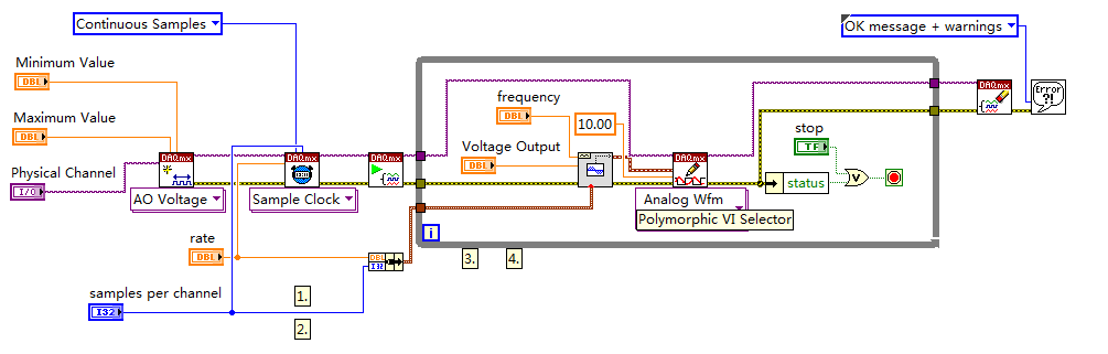
I am currently using a PCI-6251 DAQ card with a block of connection BNC-2120. I have a VI (one that is attached to this topic) that will essentially be an analog input signal and produce digital impulses from the output of the meter to each instant trigger. I am also able to define a series of delay values such that the delay will update automatically each at intervals specified by the user or when you press the stop button. I wonder if there is anyway to change this program as the time-out value will change every instant release. So, for example, in the first trigger a pulse is produced 0 second delay, then immediately when the next instant relaxation is reached, a push will occur with a 0.1 second delay, etc... And I want that the series of the time-out values to keep looping. I tried to use my current VI, with time to stop at each iteration to be less than half of the period, so theoretically it should go to the next delay value in the next instant trigger. Then I tried to put a certain time-loop around it to keep the job going, but it doesn't seem to work. I've attached a screenshot of my attempt, please let me know if this is possible, thank you! To see what each part of the VI in the screenshot, please see the screws attached, thank you!
P.S. for the VI that is attached, the analog input signal is 281Hz, the pulse width is 2.5% of the period and the delay is in the stages of T/20.
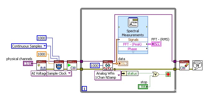
No worries,
Please see the attached block diagram image. It is important to wire terminal on the Read.VI DAQmx acquire in a constant to the number ofsamples. This will force this function to wait until many samples are available in the buffer. In my example, you will get 1000 samples per second (because my rate is 1 kHz). and these 1000 were submitted directly to the FFT. What happened for example of you, it is only because you have not specified the number of samples to read, it is by default (-1), which means that the DAQmx Read.vi will pull all the data that is available in the buffer at the time. So if you had only 2 samples in the buffer that your FFT will have only two samples on average and as a result it will fail. Try this and it should help!
-
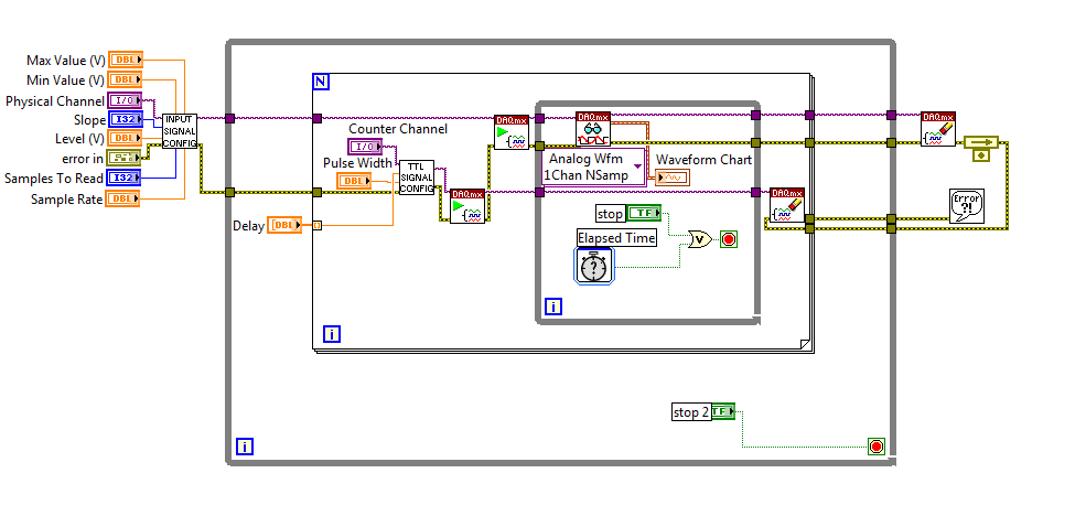
How to build square 3 ph pulses and use them to trigger the two analog inputs.
Task:
1) generate continuous 1 Hz ms 45 pulses on three lines of output offset 120 degrees.
Other neighborhoods, three phases (three outputs) 120 degrees out, but instead of sine wave should be a volt 5ms 45 along with a second ground pulse. I need these impulses to control an external circuit. The tolerance of 1 Hz is loose, but 45 ms must be at 100 us.
(2) measure (trigger) two independent DC voltage over 45 ms 50 ms after each front (leader) amount of each pulse. 45 to 50 ms must be 100 us.
Other neighborhoods, begins each measure 45 ms for the DC source #1 and 50 ms for the source DC #2 after opening (rising edge) of each pulse for total of six measurements per second 1 (by 1 Hz cycle).
(3) an analog output must provide ongoing (to be booked) negative DC voltage to be used as a source of supply for external circuits.
I timely when I can generate the 45 Hz by using CO (0) 1 ms pulses continuously and the trigger I (0) on falling edge. I (0) is hard wired to triggering I (0).
How I do HAVE another (1) and two other lines (two phases) and link them to HAVE (0) and HAVE (1)?
Equipment: LabView 8.6.2, PCI-6221 (37-pin)
Hi behappy.
Thanks for posting and welcome to the forums EITHER! I think we can get what you need with the variety of the 6221 37 pins:
(1) our machines of the M series have 2 counters, so you cannot generate all the impulses of 3 of these alone. A solution would be to use outputs digital correlated.
Unfortunately, the 37 pins 6221 has only two IO digital correlated, so you should use a strange mixture of digital meters and IO to implement three impulses. It would still be feasible - for example, you might use a counter for a time base for the digital i/o lines and the other counter to the third output pulse. You would have to match the beginning of the two counters to ensure the phase of your signals.
2) there are essentially two parts to this question, so I'll try to split:
(i) combine the three impulses together to generate a single sample signal out of. I think this would be doable on a different set of M with a higher number of digital I/o lines correlated using change detection (see the user manual of M series). However, at this stage, we are just out of digital lines correlated to use, and I don't think that's possible on the 37 pins 6221.
If you use the 6221 37-pin, which you will probably need to do is to provide your own external circuits OR three pulses together.
(II) get the 5 ms delay to enjoy your second channel. Since you have already discovered that you can sample the falling edge of the digital signal for the delay of 45 ms, you would just add another delay of 5 ms before taste you your second I. You should be able to do this by setting the clock to convert DAQmx frequency (5ms corresponds to 200 Hz). The clock to convert, it's what actually sampling data (keep in mind that the boards of the M series are multiplexed).
To do this, simply use the property calendar DAQmx node, then select: more > converted > rate.
(3) this one is easy - we have not yet used all channels of AO.
So the 37 pins 6221 is a little less ideal because you have not enough correlated digital i/o to make the generation of pulses or change detection - but he has yet to do the job if you can combine the three impulses yourself outdoors and don't mind not using the additional counter to generate the third impulse.
I hope this helps, if you need any help to find relevant examples, please do not hesitate to post in return. Thank you!
-John
-
Want a ramp of output voltage over time and measure input 2 analog USB-6008
Hello
I want to produce an analog voltage output signal that increases over time with a certain slope, which I'll send in a potentiostat and at the same time I want to read voltage and current (both are represented by a voltage signal) that I want to open a session and ultimately draw from each other. To do this, I have a DAQ USB-6008 system at my disposal.
Creation of the analogue output with a linear ramp signal I was possible using a while loop and a delay time (see attachment). Important here is that I can put the slope of the linear ramp (for example, 10mV/s) and size level to make a smooth inclement. However when I want to measure an analog input signal he's going poorly.
To reduce noise from the influences I want for example to measure 10 values for example within 0.1 second and he averaged (this gives reading should be equal or faster then the wrong caused by the slope and the linear ramp step size.) Example: a slope of 10 mV/s is set with a 10 step size. Each 0.1 s analog output signal amounts to 1 mV. Then I want to read the analog input in this 0.1 s 10 values)
Because I use a timer to create the linear ramp and the analog input is in the same loop, the delay time also affects the analog input and I get an error every time. Separately, in different VI-programs (analog input and output) they work fine but not combined. I searched this forum to find a way to create the ramp in a different way, but because I'm not an experienced labview user I can't find another way.
To book it now a bit more complicated I said I want to measure 2 input analog (one for the voltage of the potentiostat) signals and one for the current (also represented by a voltage signal) and they should be measured more quickly then the bad of the analog signal. I have not yet started with because I couldn't read on channel work.
I hope someone can help me with this problem
An array of index. You want to index the columns for a single channel.
Maybe you are looking for
-
I have a problem with my safari alerts. They recently began to look weird. As the sale won't and I don't know exactly what it is. I'm on Safari 9.1 or OS X 10.11.4 and it is their appearance. Any of you guys can help me? Thank you!
-
Suddenly, I noticed that my MacBook Pro felt very hot. I open the activity monitor and mds was using 99% of resources. It ran for four hours and then abruptly stopped. The keyboard and the underside of the MacBook Pro are now cooling. I could hear th
-
Project properties: separately compiled code?
I'm refactoring the code in LabVIEW 8.5 to LabVIEW 2013 SP1 with the intention to create an executable file with an installer. I tried to create an executable of my project and when I ran it I got a bunch of error code 59: compiled code in the source
-
HP MINI 102 CNU032OTYO FATAL ERROR
-
E 280 Firmware * beep *-to the top!
I have an E280 and recently heard talk about firmware updates and thought - what a great idea! In my ignorance, and I went along to the site and downloaded the UpdaterInstaller, ran what I thought was the update of firmware for my drive, and in the p