9421 sinking digital input module toggles output
I have a digital input module 9421. I'm only using a single port (0). The line is 'high' all the time. I can see it on the lights and the tool MAX. I can turn on/off the line and see the LED and MAX change, so I know I have the cable correctly thing. But in normal operation, it is always powered.
It is, when I run LabVIEW mode trace with a probe on the output ExpressVI DAQ, I see that all the other times my code, the output of flicks from true to FALSE and vice versa... and so on. The acquisition of data ExpressVI is inside a while loop.
Any thoughts?
DH
I have chosen the cDAQ "simulated".
DH
Tags: NI Hardware
Similar Questions
-
9421 sinking digital input toggles output
I have a digital input module 9421. I'm only using a single port (0). The line is 'high' all the time. I can see it on the lights and the tool MAX. I can turn on/off the line and see the LED and MAX change, so I know I have the cable correctly thing. But in normal operation, it is always powered.
It is, when I run LabVIEW mode trace with a probe on the output ExpressVI DAQ, I see that all the other times my code, the output of flicks from true to FALSE and vice versa... and so on. The acquisition of data ExpressVI is inside a while loop.
Any thoughts?
DH
I had selected "simulated" cDAQ

DH
-
NI 9421 - Digital input Module
Hello
We have a 9073 cRIO chassis and a digital input module (NI 9421). We installed also driver on this website - http://sine.ni.com/psp/app/doc/p/id/psp-177/lang/en and added 'modules C series' under the 'chassis (cRIO - 9073)"as shown in the illustration #1 as an attachment.
True to use 9421 is this way? And should we right click and select "deploy all '? And how can we resolve the conflict as pictured #2?
Thank you...
Hey drycsr,
First of all, make sure you have the drivers and rt versions listed here:
FTP://FTP.NI.com/pub/DevZone/tut/crio_software_versions.htm
Since you seem to have most of the currently running system, I think that you do not have those are installed.
To solve the problem in photo 2, follow the instructions to install on your cRIO scan engine support. This document is for PXI chassis, but it explains the general process:
http://digital.NI.com/public.nsf/allkb/D170D1AF82303EA086256B4200780579?OpenDocument
This document may also be useful:
http://zone.NI.com/DevZone/CDA/tut/p/ID/7191
As for your other question, you seem to be using the hybrid mode, which uses both FPGA (you have your module to your FPGA project level) and the scan mode of the interface (you have your module to the "frame" of your project level). This is not necessarily recommended for reasons explained here: http://ae.natinst.com/public.nsf/web/searchinternal/61276465e3043c0c8625749e005cc8a1
Scan by itself is discussed here: http://zone.ni.com/devzone/cda/tut/p/id/7338
FPGA and scan mode to discuss in the guides started can be found here:
http://sine.NI.com/NP/app/main/p/AP/global/lang/en/PG/1/SN/N24:cRIO/fmid/104
Good luck.
-
Hi, could someone please advise me on the following: I plan on the use of the module in the series c with a compact RIO 9425 to detect various devices 24V DC signals. Can I just plug the plug of DI to the positive terminal of a 24V + power and the COM pin to the 0V of the 24V power supply? The card then detects when the power is turned on and provide a path to the DI pin too the COM pin so compelting the circuit. Or should I connect to the card in a different way? Regards Robert Foat
This module is made for 24 v logic. So yes, you can simply plug your blood directly into the entries. It was to provide resistance 30kOhm grounded (impedance of entrance in the spec). It is generally not a good idea to rely on a digital input to complete a circuit. The digital input should be a meaning.
-
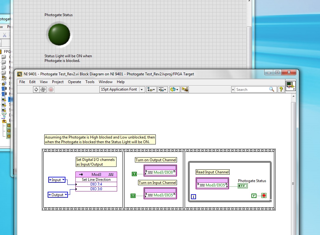
Playback of digital input [FPGA] - NI 9401 - questions?
I'm having some trouble with the digital input NI 9401, which is to have a uniform reading. I have a photogate that power of a digital output is turned off and goes in to a digital input module, but I can't read the entry several times. My LED flashes once and never again will blink until I restart my CRIO or recompile. I have launched the ports of entry and exit, their market and constantly for loop. Any idea what's going on?
Hi Allan,
Why you "light up" a channel of entry?
Writing a value to a DIO PIN is usually for outings!
What is connected to your PIN DIO 5? Have you checked the entry with a DMM measure?
How long the impulses are measured with this entry? Do you really you can see short pulses of light flashing?
-
With the help of digital input for Boolean control?
Hello!
I have spent a lot of time to search but have not found a solution to this...
I have LV 2015 with chassis NI 9188 and module NI 9425 DI. Try to use the input signal to assign a State structure machine program and/or events in real time. It would be acceptable to have an indicator show the status of the input line, since I can use it elsewhere with Value (Signaling).
Please do not ask for the code - the problem is quite simple. I just want to use the digital inputs to program control as a T/F. I want just the program to analyze the State of the input and decisions - a bit like a PLC.
All I seem to be able to extract is data of digital waveforms with a task DAQmx.
It's not a trigger - I already use a trigger to start the analog acquisition.
Formulate the problem in a simpler way... What to do if you had a digital input module and you wanted to see the status of each input line in the form of a LED on your face in real time. How would you do it?
I really appreciate the help!
greyhorn23 wrote:
Formulate the problem in a simpler way... What to do if you had a digital input module and you wanted to see the status of each input line in the form of a LED on your face in real time. How would you do it?
I would like to write what has been read to the Terminal.
From what I can tell, you want to just read a single static value from your digital line. You can then simply read the value of one and do some logic with her.
-
Digital input to Toshiba 46TL-> no analog audio output to amplifier
Hi all
When I connect a video source (e.g. computer laptop via DLNA) to my 46TL, output TV audio analog (red/white taken connected to an amplifier) does not work.
It does, however, watching television.
Is it possible to configure the TV to read the audio data from digital input (HDMI/DLNA) to the analog output?
Thank you for the help
Not quite what series of TLxxx you have, but for example the TL938 supports a digital (optical) audio output port that provides a digital audio signal.
Why n t connect the amplifier to the TV using this Jack?Connectors for component video / audio to the rear of the TV are the ports of ENTRY and not the OUTPUT ports. So, you can send an audio signal to the TV and not the amplifier output.
-
6259 switch digital input to output
Hi all
I use the NI PXI-6259. One of the digital inputs I want to switch to digital output, send a serial code and switch again one digital input.
Does anyone have experience with this kind of configuration change during execution of the VI program.
Thank you
Basically delete the task that he had as an input, create another task DAQmx with channel configured as output, this task, erase it, create the task with channel configured as an input.
If you need a tight with switching schedule, I wouldn't recommend this Board. You may need to set up a Council of RIO with LabVIEW FPGA.
-
Digital input and output problem
Hello:
I do a test for digital i/o:
for a table of the digital signal to an output of data acquisition in the digital input to detect the output signal.
(bascially, it's like a loop that goes outside the material)It's pretty simple, as shown in the attached fichier_1.
It works well.
The manual light switch controls, which means that inputs and outputs are ok.Then I went on the low level DAQ for better speed, as in attached fichier_2.
But it does not work. Especially when I pressed stop to abort the loop, an error has occurred:To speed up, I went to the low-level data acquisition as the fichier_2 attached.
But it does not work. Espeically when I press the "stop"button to exit the loop, the error occurs.Possible reasons:
Requested value is not supported for this property value.
The value of the property may be invalid because it is in conflict with another property.Property: SampTimingType
Asked the value large clock
You can select: on requestI don't understand why the sampling time has a conflict here.
(It is probably just something very simple in data acquisition, but I checked a few examples and did not find a clue).
Hope someone can give me a suggestion.Ultimately, my goal is to make the attached file_3.
In this one, I generate a digital output, and then lead to the entrance.
Then I can take it as a signal to trigger my other task.Note:
I use a similar conti signal to control one of my camera.
I need to sync it with my another task.
So I think to generate a digital output (which share the same clock as the signal similar to the data acquisition device), then put it in one of the digital input.
By detecting this digital input, I can trigger my task and synchronize with this signal similar.
My camera's USB-6211.
I am aware of the latency of USB, but once the value is a constant value, then the synchronization is always good for me.
Actually, I was using an analogue at the entrance of the to do it before, it may work, but the synchronization error is too big for me.
I need to do some calculations/judgment for this analog value, which makes the time difference varies.
So I'm trying digital entry now and I hope that the digital input can trigger my task with a stable latency.Thank you very much
Have you looked at the specs? It clearly states that the digital I/o is a programmed software. You have not any hardware clock at all. The best rate that you could possibly achieve is around 1 kHz and which would have a considerable jitter the nature of non-determimistic of windows.
-
Hi all
I meet a scenario where the digital input on my DAQ card channel giving 5V when I measure between the channel and the ground. As a result, I was not able to read the digital signal. This happned in the past, a few months ago and my work around it is to switch to another channel. This time, I feel the same thing using my FlexRIO + OR 1483 module. There are four DIO channels and I have them configured so that came in 2-channel and 2-channel output is. Initially, everything worked fine, but somehow, these last two days, I wasn't able to read DI channels. During the inspection, we discovered that DI (at NI 1483) channels provide 5V.
I hope someone could shed some light on the phenomenon.
Please advice.
BEA
Take a look at the spec, maybe a pull from the top of resistance?
-
Hello
I searched for centuries for the answer to what I thought was a simple question - the iMac has one digital input (optical or other)?
I know that the headphone port doubles as an analog audio to as well as an optical digital output, but this port also accepts input optical? If not, is it possible to enter a digital signal via a USB port?
I have an iMac (20-inch, mid 2007).
Thanks to all who can help.
AL
Yes exit usb audio and are truly comprehensive external soundcards, they can have any type of entry and exit of the machine to be desired that they have
and if they do a driver of OS x for him it's just a matter of connection installing the driver and choosing the entry in system preferences for being that
If the audio minijack that also take in charge the headset for iPhone I believe support the digital input and I don't know if
-
Hello
After reading everything that specifications and manuals, I decided to ask a general question.
In the data sheets, user guides I've read, in general, there are two warnings for DIO:
-Do not connect the outputs digital circuits which operates above the limits.
-Do not drive the line with tensions outside its operating range.
Generally speaking they tell me I need to know when dealing with output and voltage when dealing with entries. So I have this question, can I wire a power supply for digital inputs directly without exceeding its "beach of normal operation and without any protection circuit? In fact, my feelings, this is not possible. But why certain documents produced clearly mention that the impedance internal inputs while that of others is not clear those? How can I determine if I can connect a signal directly to an entry (for example USB-6525 indicates a current limiter circuit, but I don't see a clear explanation in the datasheet USB-6251)?
As long as the input voltages are within specified limits, no damage will be the DAQ hardware. Logic devices often have two lines of non overlapping input, one for low input and high input. If the input voltage lies between the beaches, the performance of the device can be unpredictable. Also, check your power supply to make sure that this doesn't not exceeding when turned on or off as that could exceed the DAQ limit.
Lynn
-
Hello world
I use an NI USB-6501 and I'm trying to understand how to read the entries.
I used this card to generate output using the example vi write Chan digging, it works fine.
Now, I'm trying to use the example of reading dig Chan vi to read an input voltage. But it seems that, by default, the map reads 5V (a 1 logic) as entered on each pins, even if nothing is connected to them. I tried to connect the output to the input, use a relay to see if it detects a change in the entry, if we send a voltage or not, but it changed nothing. It still reads 5V anything.
Can someone help me understand how to be able to read an entry? This problem has happened to someone else?
Thanks in advance.
Frédéric
If you dig through the data sheet, you will see that there is a 4.7kOhm shoot all digital inputs. So with the floating inputs you will get a high (logic 1).
As Dennis have already said, wire your digital output directly into your digital input. So everything that you set the output that you will read on the entry. I don't know what you do with a relay.
-
Hello
I'm learning about labview data acquisition. So, I made a base for digital vi, with a virtual digital input device. For some reason any I can not output anything other then zero, but when I run the daq assistant (when you install assistant daq) Boolean values between 0 and 1. But, in my VI I can't get any other input then set to zero.
I enclose my VI.
Thank you
You should associate your stop button at the entrance to Stop on the DAQ Assistant. You are openening and close the task each time when you do not do this. According to me, which is also reset the activation/deactivation of the simulated device.

-
Boolean values of multiple digital inputs
Hi guys,.
It must be really basic but I looked around to find a solution with no success...
I have a digital input with multiple-entry device.
For example, I read signals 0-24VDC of pushbuttons and limit switches.I would just like to be able to assign to each entry to a Boolean to use anywhere in the code variable.
Example: I install the DAQ help and get the usual result of 'data '. I'm guessing that this generates a table of Boolean signals.
How to convert this table in a single Boolean DI signal for each entry?
Or better yet, is there a VI I should use that emits individual signals?I also have the same problem for outputs digital. I'm guessing that I'll be able to apply the same principles to the problem well.
Sorry if this is obvious and my thanks for the help.
JoelIndex table will collapse a table into individual elements.
Build table opposite taking individual values and build in a table.
I recommend you watch the LabVIEW tutorials online
LabVIEW Introduction course - 3 hours
LabVIEW Introduction course - 6 hours
Maybe you are looking for
-
No imagery in music Apple (PC)
Hi all When I use Apple music in iTunes (v. 12.3.3) on PC, I'm met grey squares anywhere where imaging (artist, album, playlist) should be. Search results: http://i.imgur.com/0vYsiMU.png in the album: http://i.imgur.com/opI4QDo.png I know it's only a
-
Safari crashes in el capitan, search bar and tabs are no longer works
Safari crashes in el capitan, search bar and tabs are no longer works. Happening right after the update - I installed another browser, Opera. That works, but I need to Safari anyway, so what to do? OS X EL CAPITAN, 10.11.3 Version
-
HP Compaq dc7100 USDT: Audio does not not on HP dc7100 usdt
HP Compaq dc7100 USDT P/N PN290AA #ABU dc7100U/P4-530/80hnd / 512 G/4 UK Windows 7 Professional 32-bit with Service Pack 1 SoundMAX Integrated Digital Audio 5.12.1.4070 driver version dated 15/04/2004 Hello I'm fighting to get the audi is working on
-
OK I tried reading other entries, and I even tried the fix it Center and nothing helped. Just one day 2 weeks ago, I turned on my computer and my cd/dvd drive has disappeared. It will open, close and spin records as usual but nothing else happens. It
-
OptiPlex GX620 with Analog Devices ADI 198 x integrated Audio and Windows 7
Hello... I have an Optiplex GX620 with built-in Bios version A11 and 198 X Audio. I installed Windows 7 on the system and it works fine, except for the Audio. In recording the sound device Panel, it does not show the adaptors to THE Stereo Mix as a