A pump for connections rs232 for real-time control
I have a genius pump more syringe (manual attached) and I need to be able to control the flow of the pump in real time of the computer, using a dial to to the top or the bottom rate as I see climb. I used the basic series vi in read/write of the examples just mentioned another detachment and he contacted the unit very well using the commands contained in the manual. My question is how I change this option or what do I have to do the program I need? I'm barely a beginner still labview but tells me it can be a very useful program for this and other future applications that I will meet you. all the advice, it's that very much appreciated, thank you!
Tags: NI Software
Similar Questions
-
Control software for real-time Applications
Hi all
We develop products based on the platform or sbRIO and deploy applications to the target in real time. We need to get these what UL listed products and part of the procedure test requires that the software be locked and not changed while the test is in progress. For this I need a way to get and display the checksum (or some other signature) of the currently deployed on the target real-time application.
Is there a way to do this? Please let me know if you need more information.
Thank you
Hi LabVIEWingToday
On the first link in the previous post, there is a section that explains what is the checksum and they recommend a community tool or a LabVIEW VI, you could use programmatically.
To calculate a checksum on the key files, consider using the File.VI MD5Checksum, which is built...
Concerning
R. Esteban
-
How 9201is used for real-time applications?
Hi all
IAM currently using labview 2009
and iam using equipment OR to work with my application
I designed an Adaptive controller for adaptive noise cancellation in labview
now, I want to use follwing material to implement my task
1 OR cRIO-9012(real time embeded controller)
2 analog input for NI 9201 module (to take the audio signal)
3 NI 9263 Analog output module (to hear the audio signal output)
How to set up these materials on real time module
can someone help me start my application
Thanks in advance
all TC
-
1042 for real-time PXI configuration
I bought
PXI-1042
8187 controller
a module for capturing data.
I want to configure the purposes such real-time pxi,
so should what steps I follow?
Thank you
Abbas
With success, I put the ip address of the PXI-8187 controller in chassis 1042.
now does not restore the IP 0.0.0.0
What I did:
Once the network is built, go to
1 MAX > remote to the pc host, right click on and select format.
2. change the IP as you want
3 reboot, now your ip address will stick to our ip is entered.
another sequence of installtion
1 - first of all, I installed Labview 7
2. then Labview real-time module 7
3. then DAQmx 7
now, when I try to install the software from remote > remove from , I do not see the LVRT7 in the list to download to the target.
-
Error trying to create the exe for real-time target
I have a target program that works well on target in real time, but hangs when I try to create an executable fron, error is:
An error occurred during the recording of the following file:
C:\Program NIUninstaller Instruments\LabVIEW 2009\vi.lib\Motion\FunctionBlocks\straightLineMove\nimc.fb.straightLineMove.startStraightLineMove.axis.modeVelocity.0.vi
Invoke the node in AB_Source_VI.lvclass:Close_Reference.vi-> AB_Build.lvclass:Copy_Files.vi-> AB_Application.lvclass:Copy_Files.vi-> AB_RTEXE.lvclass:Copy_Files.vi-> AB_Build.lvclass:Build.vi-> AB_Application.lvclass:Build.vi-> AB_RTEXE.lvclass:Build.vi-> AB_Build.lvclass:Build_from_Wizard.vi-> AB_UI_Frmwk_Build.lvclass:Build.vi-> AB_UI_FRAMEWORK.vi-> AB_CreateNewWizard_Invoke_CORE.vi-> RTBUIP_CreateNewWizard_Invoke.vi-> RTBUIP_CreateNewWizard_Invoke.vi.ProxyCaller
Method name: Save target: InstrumentVisit ni.com/ask support request page to learn more about the resolution of this problem. Use the following as a reference:
Error 6a held at AB_Source_VI.lvclass:Close_Reference.vi-> AB_Build.lvclass:Copy_Files.vi-> AB_Application.lvclass:Copy_Files.vi-> AB_RTEXE.lvclass:Copy_Files.vi-> AB_Build.lvclass:Build.vi-> AB_Application.lvclass:Build.vi-> AB_RTEXE.lvclass:Build.vi-> AB_Build.lvclass:Build_from_Wizard.vi-> AB_UI_Frmwk_Build.lvclass:Build.vi-> AB_UI_FRAMEWORK.vi-> AB_CreateNewWizard_Invoke_CORE.vi-> RTBUIP_CreateNewWizard_Invoke.vi-> RTBUIP_CreateNewWizard_Invoke.vi.ProxyCaller
Possible reasons:
LabVIEW: File generic i/o error.
=========================
NOR-488: IO abandoned operation.The second was the issue, I found myself actually apply to open with an engineer and he helped me. Thank you very much!
-
Unable to connect to a real-time target... ugh I give up!
This one is really frustrating... I did a lot with Labwindows for a long time, so get in... I just installed LW/CVI 2013 on a new machine in my lab. hooked to a new PXI chassis, formatted a new disk in and installed all the drivers. When you try to connect to the target environment labwindows I get the popup in the screenshot. As you can see, the chassis is on the network, to the good ip, and the drivers are installed on the target... What is the problem! Thank you.
Hello
This is the acutally NOR Configuration system that comes with MAX and interferes during the installation of the CVI real-time on the target.
Decommissioning of MAX should solve the problem.
If you don't want to upgrade to CVI real-time Module to 2013 SP1 there is also a work around:
Edit C:\Program NIUninstaller Instruments\RT Images\CVI\version\cvilvrt.cdf and do one of the following:
Remove the entry from CVIRealTimePeer.
Specify the IP address or desired host name.
Reinstall the LabWindows/CVI runtime for RT component to the target via NI MAX.Good day
Constantin
-
Hello
I have a compact rio, which has a 4 way frame this chassis is the three modules of ni9234, they are related using FPGAs for application in real time, then using shared variables in the low-speed loop associated with a slave modbus to communicate with the domain controllers, the nor 9234 accelerometers linked to them with option ac coupled iepe on c modules , my problem is the real-time application seems to work well even when power loss occurs it restarts without problem and the fpga written hard disk portable bin files very well, but without an accelerometer connected I get readings of low noise as soon as I connect an accelerometer to one of the outputs 10 it just goes to a fixed number (0.03125) as soon as you unplug it again He returned to readout noise, I ran a scan on the modules and get only a spike when I connect or disconnect the accelerometer, I tested voltage at the pins on the module and I get 22 volts CC which makes it more likely that the material is not the problem, but software is perhaps the cause to hang up, I join the project and files for your perusal. I also realized a new project which, in mode directly linked scan has the module entry in the shared variable and the scenerio even once again. Help would be appretiated.
Thank you very much
Jason
Whren using waveform with the 9234 acquisition, we recommend the following FPGA and RT model.
http://sine.NI.com/NIPs/CDs/view/p/lang/en/NID/209114
It can be extended as a datalogger with:
http://zone.NI.com/DevZone/CDA/EPD/p/ID/6388
or using shared variables combined with the analytical engine
http://zone.NI.com/DevZone/CDA/tut/p/ID/9851
The FPGA in all this, as well as the framework of RT have used successfully by 1000s of users. I recommend giving these a try.
-
"Waiting for in time (RT PXI target) real answer" error when the program is waiting interruptions
Hello
I developed an application to detect interruptions generated by an electronic card and act accordingly. The program was developed in labview, but she calls a dll; created with labwindows. The dll is scheduled to open the visa communication, select the events and install the interrupt handler and when an interruption is detected, it reads the value of the different registers of the map and returns to labview to view.
The problem is that when the program expects an interruption, a prompt appears with the message "Waiting for real-time (RT PXI target) real answer" and the only option I have is to click on the button to disconnect the pxi or just wait. If I wait and I generate an interrupt, the prompt disappears and the application view data as it was planned.
To wait for the following code the interruption has been programmed into the function:
While (flag == 0)
{
Sleep (1000);
}
When an interruption occurs, the value of flag set to 1 and function continues without any problem. I am not really sure, but here is probably the problem and it probably isn't the best way to wait for a break because the sleep function suspends the thread to the configured time, but at least the load calculation in the PXI is between 0 and 1%. I was wondering if anyone knows how to wait for a break without 'lost' communication with PXI and if there is a better way to do it.
Any response will be welcome and thank you for them,
Jaime
Hey there.
You see problems with connectivity it's because the thread by DEFAULT CallLibrary nodes running in is the UI (UI) thread - UI thread manages also the important things like, say, communications (especially all the connections for the VI server) and other things that you could run all the time. A CallLibraryNode is not, by default, intended to be used to execute code that runs for a long period of time. If you want to do this, you assign the execution of the CallLibrary node to run in the context of a LabVIEW run-time engine thread (by selecting to make it work "in any thread") and not the UI thread. This can be done through the properties of the CallLibraryNode. By selecting "run in any thread" the call DLL will be generally in the context of the thread running in the run LabVIEW, which is usually what is meant when even. The VI CallLibraryNode color change of Orange (UI) to blue (LabVIEW thread) so that you can quickly tell what context the appeal will be in.
The reason the interface thread user is the default thread is because most often DLLS calls need to be serialized (because of functions is not not thread-safe) and so it serves to protect the integrity of the system. However, if you know your threads are thread-safe, or you will use these threads for a while, it is best to program the CallLibraryNode to use a Thread of LabVIEW execution rather than the UI thread.
For more information on this review on these pages:
https://decibel.NI.com/content/docs/doc-9069
http://zone.NI.com/reference/en-XX/help/371361J-01/lvexcodeconcepts/configuring_the_clf_node/
DLL' happy ing.
-Danny
-
Control of data using multiple thermocouples via indicators and the waveform in real-time
I apologize in advance for this question is probably a bit simple but I'm all new to labview and the forum and could use some advice. I have a CompaqDAQ with two 9213 16 modules of track and I'm trying to read in 30 thermocouples in a waveform, but also display 30 indicators so I can mark each indicator with the thermocouple for real-time tracking. Each thermocouple corresponds to a specific location and it is essential that the interface has an accurate indication or a label for each of them. I wonder if there is an easy way to do this in addition to split the signal and have 30 thermometers on my diagram? Perhaps a table any? If I use a table to create 30 thermometers, the DAQ assistant automatically sorts the thermocouples according to ascending numerical order. For example, would be the indicators of first and second on my interface automatically assigned to channels a0 and a1 of the first module, or should I do it manually? Even for the waveform? Thank you very much!
PS - Do not know if this message had need of more details, but let me know if more information is needed, and I'll give you!
I see that you use the DAQ Assistant to create your task. Now I understand why you may have about labelling. It is easy of the seller NOR spiel booting... But in any case, you already have a task to the MAX instead of use the DAQ Assistant? The interface is similar and there may be a step or two, but your end application will be more effective and you will have more options with your data and properties. For example, I tried to update the names of physical channel in the DAQ Assistant installation program, that it let you do, but it propagates that change forward to waveform chart legend. Also, I don't know any property for this dynamic data type node, although I never use it either. I suggest the setting up of your task and channels, Max if you'd give it a go.
Since I thought I didn't really takes you all the way with you help, I wrote another one. It uses a cluster, even if it's a bit barbaric. I thought that there was a more eloquent way to do by changing labels, but I could not it works as I had expected.
-
Output signals controllable DAQmx (real-time)
Hello:
I have a question here.
It is quite difficult for me, and I can't find any bad example and discussion.
Hope that some people give me some information for me to look it up.
--
I am trying to generate an analogue signal into a DAQmx device (I have an and uses it well) to control another device.
The output signal must be the sum of a background signal (which is decided, let's say a sine wave) and another control signal.
The control signal depends on the entrance of real-time control, for example by using the horizontal location of the mouse to the value of the signal.
The background signal is designed in advance and it will run continuously (should not be stopped once the system starts to ensure that synchronization between each devices).
At the same time, the control signal should be continuous. (if there is no new entry, it uses the default value or the last entry).
--
I have almost no idea on how to do it.
As far as I know, needs only one daq task to write the signal, and then she runs after.
The control signal is a thing in real time, so the task needs to be updated very quickly.
But regeneration tasks cost 50ms ~ on my computer (and I used the low levels rather than the DAQ assistant Renault).
Also, in this case, my background/control signal will be be stopped every time that when the task is regenerated (and this makes my synchronization failure.)
I checked DAQmx in real time, but couldn't find a few examples of tris and seems it isn't for my application actually (?).
A possible solution, I came is cascading my two signals once they are generated by my DAQ hardware. And then I can use an a/o to be the background signal and use an another a/o to be the control signal.
However, my control signal is always interrupted between each loop, and the method of external cascade seems not smart.
Or data acquisition is not perhaps suitable for this application?
--
Hope that some people give me some information and then I can check their.
Thank you very much
Hi Jhensi,
How the example provided was for you?
With respect to the delay that you experience, there is always a slight delay incurred as a result of underlying driver DAQmx running in the background.
In addition, your USB 6611 will have inherent delay due to being used as the communication protocol USB bus. There may be up to 100ms latency in some cases with USB 2.0.
This driver requires a certain amount of time to change the type of output signal, that is production.
A user will never really feel a 'Real-time' experience when you use an application that uses DAQmx. Deterministic control applications almost always use an FPGA with a real-time embedded controller.
It is possible that other delays are due to timing considerations in your code but if you checked these it may be a hardware limitation.
If you could let me know how you do that would be great.
Kind regards
-
Real - Time apply a few times using archived log file
Hi all
I have a doubt about the real time apply in Oracle 10g 10.2.0.4 version where the arch process has been configured on the primary and standby has been configured for maximum performance with real time mode applies.
But in the alert log file shall I use to find the message below rarely
So my question is why the archived files are applied pending have been configured for real-time if applies where it should apply only from logs in mode standby online.Media Recovery Log /oraclearch/oraarch/ctdr/5548.dbf Media Recovery Log /oraclearch/oraarch/ctdr/5549.dbf
Also I can't find any information on the eve of the database in the view v$ standby_log that these pending online log files have been archived in the column archived, then how to find how much data was written by process Srl rfs...
-YasserHello
The server process (RFS) remote file writes data to redo in files newspapers awaiting restoration by increase the standby database, application services log can recover again waiting for redo log files, as they are filled.
Please visit http://download.oracle.com/docs/cd/B19306_01/server.102/b14239/log_apply.htm
Thank you
Baskar.l -
remove the pop up message "Waiting for in time real (target CompactRIO RT) to answer.
Is there a way to remove the pop-up message "Waiting for in time real (target CompactRIO RT) to answer" what power is removed the cRIO or when the network cable is disconnected?
Hey Danny,
How did send you the commands to the Windows PC the cRIO? You use the remote FPGA host Interface?
I've seen the pop-up dialog box when the LabVIEW project is not present.
If you create a Windows VI that sends orders via shared variables or other network mechanism to a VI RT, which in turn controls your FPGA VI, then you should not ever see the popup you speak.
This tutorial walks through creating an example of monitoring on cRIO with three screws as indicated:
http://zone.NI.com/DevZone/CDA/tut/p/ID/11199#toc4
This tutorial is an example of the use of a shared variable to implement a heartbeat, to determine if the cRIO is connected:
http://decibel.NI.com/content/docs/doc-11046
I hope this helps.
-
I haven't used itunes for some time and now have a new PC. I've updated my account (change password) but when I connect to my music went? I am working on Win 8 and still have part of my collection on an ipod.
Unless you subscribe to iTunes game (which is not a complete solution anyway) your iTunes Library is on your previous PC - solution the easiest is to copy from here or from a backup. For more information, see How to move your iTunes library to a new computer - Apple Support . Previous purchases from the iTunes Store may be available for re - download - see download your past - purchases of Apple Support.
If none of these approaches allows to recover the contents of your library, see user turingtest2 on recover your iTunes from your iPod or an iOS device library for a list of tools and methods that can be used to copy the media etc from iPod to iTunes.
-
For a sequence in real-time output variable
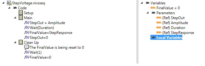
VS 2011, I have a sequence of real-time voltage step that sets an AO for a voltage given for awhile, and then resets the output to 0.
Just before setting the output to 0, I want to read the response of my this stimulus of an AI System I call StepResponse. To do this, I place this in FinalValue I set as a Variable in my script. In other words, it is a parameter or a local Variable.
Now, how can I get this out FinalValue? I don't see anything on how to "test" this variable to one of my user variable... I was able to do with the stimulus inherited in VS2010 Editor. Now, I'm stumped.
Here is the sequence:
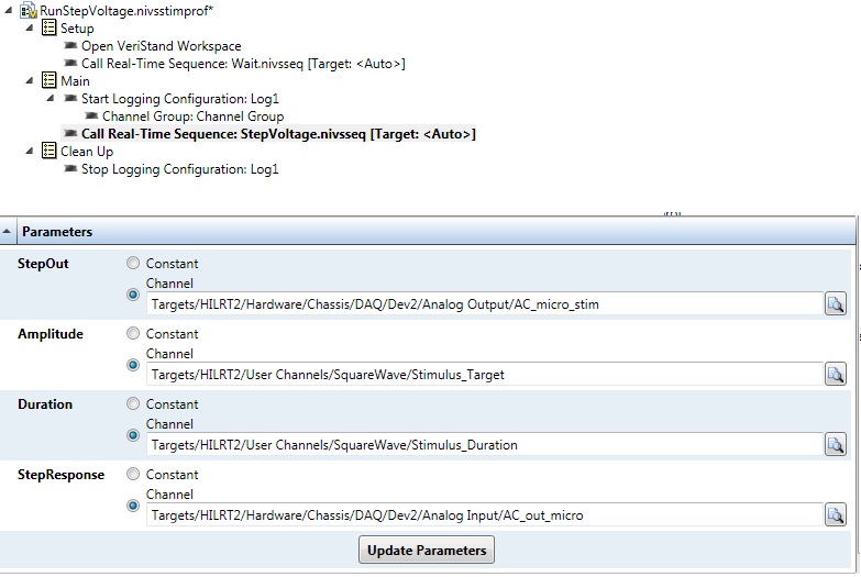
and this is the profile of stimulus and settings below. I can set the fine settings via the API of LV, or run the Publisher of the Stimulus. But I can't seem to get out this FinalValue...

THX.
L.
The return for a sequence (in your case FinalValue) variable is returned to the caller once the sequence has been completed as a result of this sequence. In your example, the appellant is stimulus profile that you configured. In a profile of stimulus, two relevant things will come based on the return value of variable a sequence called:
- The return variable value will be get recorded in the file of test result ATML for stimulus profile
- You can configure an assessment of output for the call to test sequence make a basic on the return variable test to determine a pass/fail result. For a numeric variable to return such as FinalValue, you can do a check of numerical limits to test whether the value is in or out of the specified limits. For a Boolean return value, you can translate either directly in a pass/fail result, or you can reverse the logic as well as False implies Pass.
In addition, the LabVIEW API has a function, you can call once the sequence finished to programmatically retrieve the return value.
However, in your sequence after that you store the value StepResponse in the return variable, you reset to zero before the end of the sequence. If your sequence always returns zero. I think that you do not remove this line and let FinalValue what so that you will get the StepResponse back closure instead of zero value.
-
LabView is in real-time for Compact FieldPoint necessary?
Hello!
LabView is in real-time for Compact FieldPoint (CFP) necessary?
(in German: Ist für die von Compact FieldPoint LabView time use real necessary?)
Thank you.
Bye, Ouafa
Hello
If you just want to use Labview for logging and graphics (via Ethernet) AND that you do NOT use a CFP-real-time controller, you don't need to LabVIEW Real-time.
For example if you use OR cFP-1804-Ethernet/Serial Interface for Compact FieldPoint.
(http://sine.ni.com/nips/cds/view/p/lang/en/nid/202527)
If you are using a controller real time you WILL LabVIEW Real-time.
You can't function without it!
Best regards
Mencef
Maybe you are looking for
-
the folders pane does not illuminate
lost my folder pane when I go into Options > Presentation > Classic view the folders pane is disabled and does not allow me to select any other point of view, or
-
HelloMy Skype account is used on both the mobile and computer, but never connect automatically.Recently, I noticed that even if I am offline, my account appear on-line to other Skype accounts. What can I do? I have changed my password twice last mont
-
Model: Toshiba NB300-108 Hello I lost my recovery discs that I had done with the toshiba recovery tool and also do not have the recovery partition on my hard drive. Is there anyway that I can download an image from somewhere?
-
High temperature on my Satellite A100-159
Hello I have my laptop almost 5 months now and this week it crashed during a game, and I had to wait until it has been cooled before that I could start him again. Since then, I have installed speedfan to check the temperature when I'm just on the net
-
Bootcamp disappeared. How can I get that back?
I just upgraded to El Capitan. Now my Bootcamp is not available at startup. How can I get that back?