Absolute precision PXI-6123
Please see page 4 of the specifications for the device. The signal that I'm trying to measure through a shunt 30A: 300mV, but in most cases, the maximum value is about 10 A/100mV. The readings that we receive are not clean and are quite loud, when the hope is that they are quite clean.
It seems that the smaller card voltage range is +/-1.25 V. According to the manual, the absolute uncertainty according to the table is 740 uV (or 0.74 mV). I watched it and it was quite high. I mean in 2A (20 mV) absolute uncertainty of 0.75mV is 3.75% and it is quite high. I realize that we use only about 4% of the voltage range and it is a problem, but I still think it could be better that it's - am I interpreting this right?
If I interpret it correctly, then is card on par with the industry standards?
Hello
Please clarify, I was more in the way of solving problems to try and get the best representation of your signal! Take a look at this article by NOR retailer the absolute accuracy. You can calculate this using the values in the table on page 4 of the manual you mentioned.
How to calculate absolute precision or the accuracy of the system?
http://digital.NI.com/public.nsf/allkb/8BA2242D4BCC41B286256D1D00815B90
There are three ways to calculate absolute precision in anticipation of your system design, although I'll add the specification on page 4 of the manual I believe is the number planned and tested by NOR. I apologize because I'm a little busy right now or I would run the numbers myself.
Absolute accuracy specification is a signal that properly uses the +-1.25V range. A 0.74mV absolute precision in the schema of a 2.5Vpp signal is less than two-tenths of a percent error (0.185%). There are modules (as you mentioned) for smaller ranges of entry, that's why you have seen a performance much better with the-range 0.5 to 0.5. You might consider to amplify the signal in the range of +-1.25 to get the best performance with the PXI-6123. Although the distortion seems to be important in your application, using only 4% of the available range is just a case do not use the material best suited to your application.
Kind regards
Train of Finch
Tags: NI Hardware
Similar Questions
-
Where can I find PXI - 6123 registry definitions based on records of communication?
Well, the subject line tells it, I hope. I need to write a driver for the PXI-6123. I prefer a VISA driver because our data acquisition application is written in Java. I have already created a wrapper for Open Source Java VISA that can be found at jvisa.sourceforge.net. To write the PXI-6123 driver, I need the relevant definitions of communication. I don't even know if the card supports the registers or messages.
If I can't come by this information, I guess I have to write a driver written in C using the DAQmx API and create a JNI wrapper around this driver.
Hi Gunnibaba,
Have you seen the DDK NI Measurement resources and material? If this is not the case, they are:
Measuring equipment NI DDK (Driver Development Kit)
http://sine.NI.com/NIPs/CDs/view/p/lang/en/NID/11737From the FAQ, it seems that there is an example for the NOR-6133, that is in the same family of instruments. You can start by looking at who:
Measurement Hardware Driver Development Kit (DDK) frequently asked Questions
http://digital.NI.com/public.nsf/allkb/2D93070A3DDEFD7186256C59007289E6
Please note that this kit is supported on a separate instance by R & D only:
http://forums.NI.com/T5/driver-development-kit-DDK/BD-p/90
If you have any follow-up questions, please post them on this forum.
Kind regards
Kyle S.
Technical sales engineer
National Instruments
-
Understand and improve the absolute accuracy
Many sculptures absolute accuracy calculated the computation of absolute precision in the manuals of the user for the use of modules in series C the following entries:
- TempChangeFromLastExternalCal = 70 * C
- TempChangeFromLastInternalCal = 1 * C
- Sigma/Std-dev = 3
- # of samples = 100
I have a few questions about these two values listed above TempChange
- Why such a low value of only 1 has the TempChangeFromLastInternalCal * C; modules are continually doing internal calibration automatically?
- Regarding TempChangeFromLastExternalCal, I read correctly that NEITHER is the calculation of accuracy, assuming that the material has seen a +/-70 * C delta temperature since the last time it was calibrated externally. that is calibrated to 25 * C, but runs at 95 * C?
To improve the absolute accuracy, I'm curious to know if the following two statements would improve accuracy:
- The material exists in an environment temperature controlled with a + / delta 10 * C ambient temperature. Can I use the value of 10 for TempChangeFromLastExternalCal if it has been calibrated at room temperature outside?
- If I'm short so HAVE them + HAVE terminals and a channel not used by COM and the extent to which results can be subratcted of readings of all other channels, I essentially elimited the error of the formula of absolute precision shifting?
For completeness, for absolute accuracy formulas are:
Absolute accuracy = ± (VoltageReading * GainError + VoltageRange * OffsetError + NoiseUncertainity)
GainError = ResidualAIGainError + GainTempco * TempChangeFromLastInternalCal + ReferenceTempco * TempChangeFromLastExternalCal
OffsetError = ResidualAIOffsetError + OffsetTempco * TempChangeFromLastInternalCal + INL_Error
NoiseUncertainity = (RandomNoise * sigma) /(# of samples)Hey Sean,
Change in temperature refers to the temperature difference from the last time that you did these two calibrations and the current temperature unit. So if you did an internal and external calibration at 25 ° C, then you will find the difference between the current temperature and 25 ° C. This is valid for two years for external calibration (according to the data sheet) to answer your questions:
(1) If you both internal as external calibrated at 25 ° c, and then assign TempChange 1 ° C if the environment is in a summer of 24 or 26 ° C.
(2) if the room was 10 ° C when the measurement has been taken, both internal and external TempChanges is 15 ° C (because your calibration conducted at 25 ° C).
(3) If you were doing an internal calibration at 10 ° C, then your internal TempChange would be 0 ° C and your external would be 15 ° C.
Regarding tips, I do not have too. The best I can suggest is to use a lower range and a device that has a lower production, but I don't think that it would be viable for your application. The best try of course is calibrated as close as possible to the more uniform temperature.
I found a VI that calculates the absolute accuracy of a device. Must be a lot of values, but it allows you to play with the values to see what you can afford. My calculations show you in your range, but be absolutely sure of these fluctuations.
https://decibel.NI.com/content/docs/doc-9912
Attached a photo of the values that I used to get this error. I'm sure that the devices are calibrated at 23 ° C. Here's the manual where I found the numbers that I used.
http://www.NI.com/PDF/manuals/374231c.PDF
Sorry for the confusion earlier, I hope that this post clears up a lot of information and if it's not please let me know.
-KP
-
Level of trust associated with the details of precision in the plug
What is the level of confidence associated with details of precision in the data sheet?
Specifically, I am interested in the analog input 9205. Technical sheet here: http://sine.ni.com/ds/app/doc/p/id/ds-190/lang/en
There is a table on 2/3 by the document called 'précision Détails', and I would like to know what the level of trust is for the numbers in the table. The reason is if I can use them in my measurement uncertainty calculation.
Thank you.
Now that I read through a lot of a manual of reference for the characterization of the ADC, I believe that the following terms in the table of absolute precision were calculated experimentally with at least 100 data points and a coverage of at least 3 factor:
GainTempco ·
ReferenceTempco
OffsetTempco ·INL_Error
NoiseUncertaintyThe rest of the values are derived from these, or are supposed to be conservative values to the estimate of the error. For example, the variation in temperature since the last calibration is assumed to be 70 degrees, because that's the maximum value supported temperature change in the temperature of the device has been calibrated at.
Each term in the equation has at least a factor of expansion of 3. Therefore, the absolute precision of the measure has a factor of expansion of 3.
Jeremy P.
-
Hello
I'm getting some strange noise on my with a BNC-2110 connector PXI-6123. I think that there is a problem with the card. I have confirmed that the signal entering the card does not have this noise.
Anyone seen this before? This jumps up to .015mV of the clock pulse, then goes back to the expected signal.
Thank you
Dan
I shorted the entrance of best in the world and you still see the problem.
I think I have the faulty card.
-
Synchronization of HAVE several devices in the PXI by the Sub - VI of DAQmx create channel
Hello
There are two PXI-6123 cards in the slots of the PXI-8109, and then I would acquire the simultaneous analog input signals.
The manual of the PXI-6123 recommended with a common time as a master Timebase and base to the slave devices.However, I wonder if I can take advantage of the method as the accessory, including all channels to HAVE the devices in the physical channels to create.
Does it work? How can I know what are the "some data acquisition hardware OR" in the passage of the attachment?
Hello
Please refer to this KB: http://digital.ni.com/public.nsf/allkb/78E44565FD87E7D686257108007F94F8. I think that you are good with your two PXI-6123 devices, if only you DAQmx 8.1 or later installed. If please come back and let us know your test result.
Thank you
Phil
-
Absolute best strategy for crops
What is the best strategy for high precision when the weather is not a question of culture and and want quality 'perfect '?
What is the best strategy of absolute precision low cropping when time is an issue and the standards are still high?
It is has got to be different strategies to achieve this, and I was curious to know if we could pick a winner.
Thank you
Heh, Marian, that about sums it up.
In all seriousness... How to connect 'precision' with 'cropping '? I always thought 'crop' as it is more based on artistic judgment, not something for accuracy. Maybe you could describe your photography and what you expect of your workflow?
Are you cropping the photos of documents? The people? Stars, nebulae and galaxies?
It's the 'precision' you're talking about an attempt to express "a minimal loss of pixel data? If this is the case, download the computer more powerful you can and always work to oversampled resolutions. And don't re - sampled during cropping.
One last comment: consider using the crop tool in the Camera Raw dialog box. It stores the metadata indicating future conversions how to crop the image, but the original raw data are all still intact. Note that you can open a range of images in Camera Raw, do the exhibition and cultural changes and click [OK] to save only the metadata.
-Christmas
-
Question of timebase NI PCI-5154 digitizer drift
Hello NOR all awaits them:
We have a NO-PCI5154, used for several years now. We use it to capture waveforms of impulse which we care about timing relationships.
We operate the digitizer to sampling of 1 GHz and up to today, we assume the sampling rate is precise and constant. Today, a member of group doubt that since the digitizer specfication said, what the time base drift on "±7 ppm / ° C". So if this is true, suppose we have a Temperation of exploitation that is 20 degrees higher than the temperature at which the scanner has been calibrated, then the derivative can reach up to 140 ppm time 1 GHz which is 140 KHz? It would be a killer of our measures.
Please help clarify this question, then we can estimate errors in our measures.
Unfortunately, we have no data on the repeatability of the time base drift.
To calculate the frequency of real-time database, simply reverse the calculations that we've discussed so far. Measure a source very precise on the digitizer, and any change in frequency of the signal would be caused by the non-ideal time base period.
For example, you measure a signal from 10 MHz to 1 GHz, and its frequency is reported as 10,001 MHz. So, we're out of 1 kHz. 1 kHz = 10 MHz * Xppm, solve for x: X = 100 ppm. Thus, our sample clock runs at 100 ppm. 1 GHz * 100 ppm gives us a period of 0.9999 ns or ns 1,0001. As our frequency has increased to 1 kHz, the signal was compressed when being interpreted to 1ns dt. Thus, the real clock period was 1.0001ns.
Because it sounds like you can't control the temperature of your work environment, to the more specific measures that you can measure the time base clock drift immediately before and after taking your measurements. If you have run your tests in a controlled temperature environment, you might be able to get away with a measure not time base clock drift as often, but you should always run regularly. The reason for this is also due to the effects of aging of the time base oscillator (affects all oscillators). The accuracy of all the oscillators gradually drift or increase over time. Our specifications, take account of this drift in the external calibration interval, but if you're going to measure the actual accuracy, the time is another factor that will affect the accuracy of the time base.
For completeness, I also need to say, that when you measure your test signals ppm accuracy, this shows absolute precision, not only the accuracy of the time base, but also the accuracy of the source of the signal. So it is very important to have a precise source for the test signals.
I hope this helps.
Nathan
-
Number returned to voltage conversion
I am writing an app to acquire data using PCI cards in VB.net with VS2010. I "assumed" that for a 16-bit card was 65536 heads available for the used range (09:50, etc.). Experience that has not been corroborated. In theory, using the above values, 10 volts volts equal to 32768 and - 10 would equal-32767. I constantly receive lower values.
Can someone tell me if this is correct: there is a 16 bit, 65536 counties map covering the entire map (INCLUDING OVER VOLTAGE RANGE)? In other words, I need 10 volts of input, take this indictment and then entry-10 volts and that would determine my range of work of the charges?
Hey Dan,
If these values are not too crazy about what I expected (not much either).
I guess that it is more a function of calibration and absolute precision.
I would check page 4 and 5 of the technical manual for the 6220:
<>http://www.NI.com/PDF/manuals/375200b.PDF >
It details the absolute precision, given a number of factors that could explain your results.
Also the installation of the samples, you must specifically include in your installation of data acquisition:
<>http://digital.NI.com/public.nsf/allkb/0EA34D565632DFE186256E7B00762DCC >
and then they can be found in the following locations:
<>http://zone.NI.com/reference/en-XX/help/370473H-01/mstudiowebhelp/HTML/locateexamples2010/#netxp >
I hope this helps!
-
How to display the voltage and current of synchronously
Recently, doing a project on the acquizeing voltage and current synchronouly, then display. the design is welding a resistor(1%) 0.5 ohm in NI 6251 entered analog of her HAVE differential, then acquired the differential voltage at the input to convert current. At the same time, I hope to recover the path of analog input voltage. My problem is that the current profile data. Please help me .the program screenshot is show below. ---1. Perhaps you ask why not use no. - a way to get voltage at all port of AI, then in the use of the software less to get a voltage inputs HAVE. in this way, my problem is solved. I try, but the current accuracy is failure. because my current range expect is 1uA ~ 100mA. precision current samll won't be promised if you use simple ways for granted NOR 6251 voltage. NEITHER 6251 device spec (HAVE an absolute precision) (v) nominal range sensitivity absolute Accuracy (uV) 10 1920 112 5 1010 56 2 410 22.8 74 0.2 6.4 0.1 52 6.0 (I want to use this range to measure current samll) - cordially Shawnh.Chen
shawn1 wrote:
1. how show the waveform by accumulating 1 d data table, rather than showing all 100 acquisitionUse a waveform graph. Graphics keep history, you do not have to accumulate the data. He does it for you on the screen.
shawn1 wrote:
2. What is the minimum unit of identification of the TSC103IPT amplifier? I doubt that the 0.5uA can be identified? (0.5uV = 0.5 ohm * 1uA) Because I can't find anything on the auccary in TSC101IPT datasheet.The amplifier is analog. Thus, he can win anything. But you should really think about a higher resistance if you really want to measure this small of a current.
-
6704 output range is configurable?
Hello
It is a simple question on PCI6704.
According to the specification of the range of the output is +/-10v for voltage and 0, 1 PCI6704 - 20.2mA for the current, the resolution is 16 bit. When I open the MAX test Panel, it seems to allow me to set the max/min output limit to the channels.
Question is: is this power max/min limit really configurable per channel? For example, if I put power max/min channel 0-0 / 5v, this range 5v will all use 16 bits of resolution?
Thank you
Jane
The range of output voltage on the 6704 is not configurable and is limited to the range of ± 10 V according to the manual PCI-6704 (pg a-1). Absolute precision is also referred to as ± 1 mv in the specifications.
-
Accuracy of measurement of the SCXI-1100 module
Dear team,
I'm figuring an accuracy of measurement for SCXI-1100 (http://digital.ni.com/manuals.nsf/websearch/0790D3C92CF4B16E8625665E00712865) devices.
It is not described in the standard table, it has precision stage of entry / exit (must be added?). I can't reach a precision which is a result of precision calculator. If you have any equatuions / examples please post.
Concerning
Michal
Hi Michal,
I'm not sure I understand your question. Are you trying to calculate the accuracy of the SCXI-1100 module, but you do not have the data specification for the calculation, or you don't know how to calculate the accuracy?
If you need performance data, you can consult the technical data sheet 1100 SCXI. If you want to calculate your accuracy of the device, I can recommend you following KB: How can I calculate absolute precision or the accuracy of the system?
I hope that this is the info you are looking for.
Kind regards
D. Barna
National Instruments
-
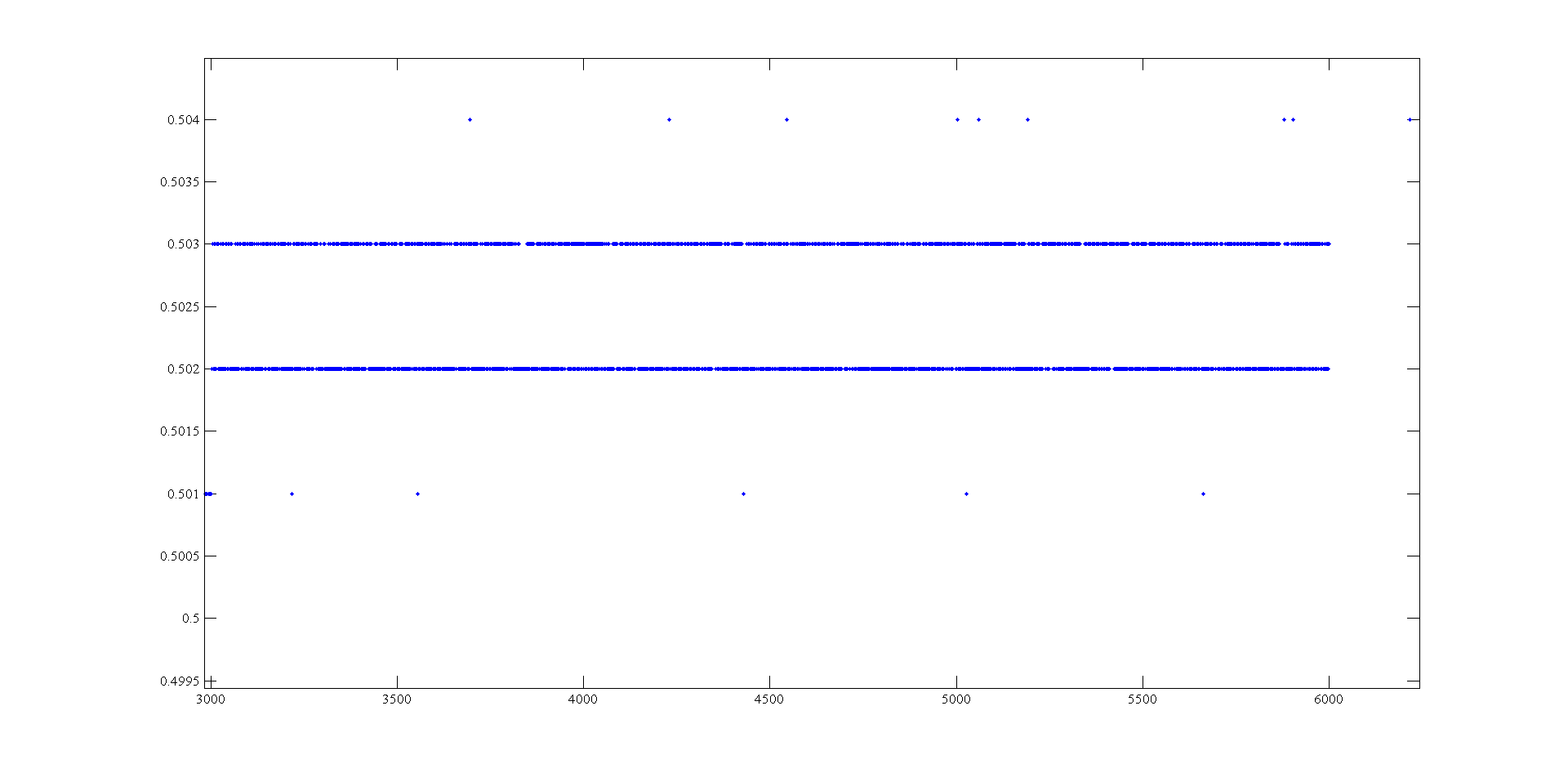
Measurement of voltage USB 6008 ranging from 1mV
Hi, I'm doing a supply at an angle for an amplifier using the USB-6008. The ranges I look are - 0.5 to 0.5 V and 0.5 to 2.5 V. To generate negative tensions, I use the + 2, 5V for a reading of differential voltage output as a 'ground '. Voltage measures have a delay that varies with the voltage, given this by drawing these variations and set the output to data acquisition there is still a 'noise' of +/-1 mv so that it is clear from this parcel of tension against the sample number:
It seems that at some point the values are being rounded up to the nearest millivolt. I need to get to a resolution of 0.5 mV for my device, it will be possible with the USB-6008?
The AO USB-600 x has a range from 0 to + 5 V and the 12-bit resolution. 5/4096 = 1.22 mV. Absolute precision is 7 mV typical and 36.4 mV maximum full scale. The noise of the AO is not specified.
If you measure the results with THE USB-6008, you have at least 0.5 mV, similar resolution system noise and absolute accuracy of 2.5 mV or more.
It's probably as good as you will get with the box USB-6008.
Lynn
-
How the output voltage is coded on 16 bits DAQmx devices?
In our laboratory, we have two devices DAQmx, the NOR-PCIe-6363 and the NOR-PCI-6733. Both have 16-bit for bipolar analog output precision. I understand that the small voltage difference that can be made is 2 * Vref/2 ^ 16, where Vref is the reference AO voltage (10 Volts or externally provided for 6733, 10 or 5 Volts or externally supplied for the 6363).
I wanted to know how the output voltage is coded. DAQmx functions take 64 bit floats as input, and at some point, they must have their reduced accuracy. How is this done rounding, is a floating point around the nearest possible tension, or is always rounded down or always rounded upward?
What is all the possible output voltages? Some diagrams in NOR-DAQmx help/measurement Fundamentals, signals, Analog, sampling considerations seem like they could involve the maximum voltage + Vref is not achievable, so I think that is all of the possible tensions - Vref + 2 * Vref * n/2 ^ 16, with n ranging from 0 to 2 ^ 16-1 included. This includes - Vref and does not zero but + Vref.
Could I get confirmation on this point, or be corrected if it is wrong?
Hi Chris,
The scale of writing DAQmx version performs double floating precision scaling and then he made a turn, the closest to convert the resulting code of the DAC to double int16_t (or uint16_t for unipolar devices). Floating point scale includes the custom scale AO if you have configured one, the conversion of volts or AMPS to the codes of the DAC and for some devices, the calibration scale.
You can check the coefficients of scaling using the AO. Property of DevScalingCoeff. It takes V / A-> CAD codes and scaling into account calibration, but not the scales to customized AO.
The PCIe-6363 X series devices preset scaling in software. The internal reference of the AO is slightly higher than 10V, to correct the errors of gain and offset does not limit the output range. It also means that you are not limited to 9.9997 V on this device when you are using an internal reference.
The PCI-6733 uses calibration DAC instead of software scaling. RAW - 32768 means - 10 V, 0 corresponds to 0 V, 32768 is impossible because of two of the 16 bits of the add-in and 32767 translates 9.9997 V. When you continue 10 V to write DAQmx with this device, DAQmx he forced into 9.9997 V.
Note that for these two devices, the absolute accuracy full scale includes over 305 uV of error. Look at the tables of absolute precision AO in the specs of the device for the full story.
Brad
-
I have a card PCI-6255 that I intend to use for certain sensitive measures.
I'm trying to put together a budget-to-end error and I have a few questions.
My model is in terms of number of analog-to-digital converter (also known as the LSB in your datasheet).
In the table of absolute precision on page 5 of the 615 x standard OR I see a column called random noise, (uVrms).
I think I understand the residual gain error, offset error residual and associated with it and the INL error, but random noise is confusing to me.
Here's why: on the +/-2V of type range, the random noise is 16 uV. On this beach, the resolution of the ADC is 6.1 uV so random noise is about 2.6LSB
If I look at the +/-5V Beach, I see a random noise of 140uV. On this beach, the resolution of the ADC is 305uV so random noise is well under a LSB.
Therefore, in the budget of my mistake, I can use "1 LSB" for noise random when on the beach of 5V, but I have to use LSB '2.6' or '3' when the type 2V range.
I expect a signal of about 150 mV riding on a 2, 5V CC. I was worried, I might need to compensate the signal (remove the 2, 5V dc) in order to use the +/-gamme.2 volts to get the best resolution. Also, I thought that I would get better sound performance too. In looking at the figures here, but looks like I'd be better off using the +/-5V range (assuming that there is enough resolution) because the readings have less noise counties (even if it's more noise volts).
I can explain the error of Gain and Offset error by injecting known signals and making a "correction of the software. Not sure, but I think I can correct for the INL also if I use a 2nd or 3rd order polynomial. It is the random noise, I have problems understanding.
Here's the question: what is the random noise in table AI accuracy for 625 x boards? Can you give an example of how NEITHER could have measured it?
Secondly, note 2 says "sensitivity is the smallest voltage change this canbe found. It is a function of the noise. "He measured with a signal to noise ratio of '1' or '2' or some other standard, or is it a calculated value?
Thank you
MG
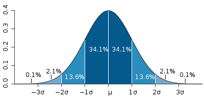
The function of Gaussian Distribution is often used to describe the noise. Random noise spec'd in the table of precision is a gap type distribution of probability of noise and was probably calculated using statistical analysis. That's why the uncertainty of noise takes into account a 3 coverage factor that represents the largest part of the distribution.


With respect, the specification of sensitivity, this requires a more detailed explanation, but it is essentially an industrial standard that takes into account more statistical analysis on a signal when awarded with noise. According to me, the mix is a compoenent of this measure.
Maybe you are looking for
-
HP deskjet 2540: suddenly can't print from iPad to HP Deskjet 2540 printer all in one
Connection wireless, everything is ok and no problem found according to the HP network configuration page
-
Data on 'Back' button pressure only when the cursor is in the text field
All, With the help of members of the forum, I understood how to use the 'Touch down?' event to send text series when the user presses the button «Back» Is there any way I can limit this function so that the data is only sent when the cursor is in or
-
No command in Intel Rapid Storage after the reset of a device of available Cache
There are in my book of 15-4010nr XT the spectrum of the HP TouchSmart Ultrabook 1 HDD and 1 SSD (30 GB). The SSD was initially used for acceleration in Intel Rapid Storage. But I zero it available in Intel Rapid Storage and now I can not "activate t
-
Change callIncoming() more than once incoming all call
Hey,. I'm working on about who gets the news. a. comments of the appellant that it is number I have a little problem that if cheking out the info. on the appellant the phone is not displayed on the incoming call screen. I want to introduce a call wit
-
BlackBerry Z10 bluescreen help please
Hello I all Z10 erased by mistake when you do a hard reset, all I have now is a blue screen, it says blackberry 10 then loading symbol lights after 100%, it's just a blue screen I tried to find somewhere on the internet to download the driver for it