Acceleration sensor signal is filtered by default?
Is there any function of filter available now? For example, filter Karman?
None of the QSensors are filtered. You will need to implement the algorithm yourself using QSensorFilter.
Tags: BlackBerry Developers
Similar Questions
-
Need to display the speed of speed Hall sensor SIgnal
Hi all
I have a speed Hall effect sensor. I'm observing the signal of the sensor to LabView via NI DAC USB-6008. Could someone please help me in the design of a logic that allows to display the wheel on Labview speed according to the reached the sensor signal? It will be really helpful if someone can come up with logic.
Thank you very much in anticipation
Sorry, that was the bad VI.
It's the good VI:
-
BB of Smartphones blackBerry with acceleration sensor
Hello
How will I know what Blackberry models have a sensor of acceleration? Is there somewhere a list, or all devices have an acceleration sensor?
Kind regards
Hi PtSyFr
You can see all the BlackBerry models and offers a http://www.blackberry.com/smartphones. However, the models of the BlackBerry Storm and the BlackBerry Torch have accelerometers in them.
Thank you
-
Duty slot in my sensor signal connection related problem class.
I fanned simple class based on the NDK documentation found here - http://developer.blackberry.com/native/documentation/cascades/device_comm/sensors/
But in my case signals do not plug on slots and returns always false. I was just wondering what I did wrong? Looks all logical.
Here's the class:
#include
#include "Sensors.h"

Sensors::Sensors(QObject *parent) : QObject(parent) {
    // Create the compass sensor.
    m_CompassSensor = new QCompass(this);
    m_Accelerometer = new QAccelerometer(this);

    // Set the orientation mode to fixed so that sensor readings
    // aren't affected by device orientation.
    //m_CompassSensor->setAxesOrientationMode(QCompass::FixedOrientation);

    // If any Q_ASSERT statement(s) indicate that the slot failed
    // to connect to the signal, make sure you know exactly why this
    // has happened. This is not normal, and will cause your app
    // to stop working
    bool res = connect(m_Accelerometer,
                       SIGNAL(readingChanged()),
                       this,
                       SLOT(accelReadingChanged()));

    res = connect(m_CompassSensor,
                       SIGNAL(readingChanged()),
                       this,
                       SLOT(compassReadingChanged()));
    Q_ASSERT(res);

    // Since the variable is not used in the app, this is
    // added to avoid a compiler warning.
    Q_UNUSED(res);

    m_CompassSensor->start();
}

Sensors::~Sensors() {
    m_CompassSensor->stop();
}

void Sensors::compassReadingChanged()
{
    QCompassReading *reading = m_CompassSensor->reading();
    qreal azimuth = reading->azimuth();
    qDebug() << "The azimuth is " << azimuth << " degrees.";
}

void Sensors::accelReadingChanged()
{
    QAccelerometerReading *reading = m_Accelerometer->reading();
    qreal x = reading->x();
    qreal y = reading->y();
    qreal z = reading->z();

    // For debugging purposes
    qDebug() << "x acceleration: " << x;
    qDebug() << "y acceleration: " << y;
    qDebug() << "z acceleration: " << z;
}
Here is the header
/*
 * Sensors.h
 *
 *  Created on: 2014-02-01
 *      Author: misha
 */

#ifndef SENSORS_H_
#define SENSORS_H_

#include
#include
#include
#include
#include

using namespace QtMobility;

class Sensors : public QObject{
public:
    Sensors(QObject *parent = 0);
    virtual ~Sensors();

private:
    QCompass *m_CompassSensor;
    QAccelerometer *m_Accelerometer;
public slots:
    void compassReadingChanged();
    void accelReadingChanged();
};

#endif /* SENSORS_H_ */
Please advise! I was fighting with this for a few days already... I bet I missed something important but s mall

Thank you
Hello! Q_OBJECT macro is missing from the top of the class declaration:
class Sensors : public QObject{  Q_OBJECT
public:
  Sensors(QObject *parent = 0);
p.s. This line changes, the first could not connect will not be detected. It should probably be & =
res = connect(m_CompassSensor,
-
Debounce counter signal digital filtering is not possible?
Hey all,.
When you read a flow meter signal at lower bitrates, the signal bounces. Because these bounces are count in addition to pulse correct, this leads to an output of counter unreliable. With a range of joint, I can see the behavior that bounces and determined that the rebounds are starting to occur around 100 Hz. The flow meter has to be in the order of 1500 to 10 Hz. remove all other devices of the system with the potential to influence the signal has no effect.
Bounces produce both on the edge of the fronts and.
Because I use a 9188 compactDAQ chassis and a meter module 9411, it seems that it is not possible to use the digital signal filtering? I want to establish that it is a correct assumption.
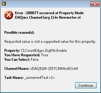
When adding a digital camera filter (see the attached VI) I get the following error, explaining that the activation of the filter is not possible.
Upgrade to DAQmx to 9.2.3 makes no difference.
I read about using a meter of output to generate own impulses (with a high enough to avoid pulse width bounce) here. For me it is not an option that I don't have an output of the meter module.
Are there other ways to get a correct count of edge output of the signal bouncing?
Kind regards
Bram bolt
Dear Bram,
You're right, digital filtering is not supported with the second chassis cDAQ generation (like NI 9188), I forgot that one (I tested with a chassis 0172 and worked well). What we can do is to measure at the same rate and filter the glitches in the software, please marine following example .
Best regards
-
Libretto W100: Access to acceleration sensors
I would like to do shows with the G-Sensor.
How can I access it?
Is there any help?
What is the driver and the name of the sensor?
It does not appear in Device Manager.Hello
It seems that the capacitive multi touch sensor is provided my Wacom.
Google a bit and found this:
http://www.Wacom-components.com/usingWacom/Welcome them
-
How to create crankshaft sensor signals Hall
I want to create a waveform with LabVIEW 8.6 and output for oscilloscope via NI PCI-6221, but I don't know how to do.
So I would ask you advise and technical support, please. The waveform is attached for you reference.
-
NI9232 adapted to the PCB - 356 has 02 sensor of acceleration
Hello
I need to measure accelerations for a Test of 'head-Impact '. My boss has already ordered an acceleration sensor 3 dimensions (but only 2 dimensions required), which can be found here: http://www.synotech.de/produkte_skript/downloads/specs/356A02_specs.pdf .
A Testengineer in my company (im a "student work" it) recommended the acquisition of data NI9232 for data acquisition, but I'm not sure if this is best suited. the +/-30V range is already too, so ill have amplify the signal of the sensor. But it is even possible to connect the sensor (not directly the sensor, but this power supply: http://www.synotech.de/produkte_skript/downloads/manuals/482C05_manual.pdf ) with a bnc connector? Article-he gave me, there were '782000-01', but this version didn't bnc inputs as much as I've seen.
Im sorry if this post is a little confusing because I have little time.
Best regards
Alexander as
With a 6 kHz of band bandwidth nealy all IEPE devive with 20 kHz samplerate and two channels will do the job.
The 30V range isn't the problem, the resolution is still quite high, with about 2% to 5% uncertaincy residual resolution of the sensor 10-bit (8 bits) will do the job. with a range of 60V and the output 10V range input (ok, say you sensor application only uses less 4V... you loose about 4 bits of your ENOBscards)
The part of the slope is the connector

The data sheet is a connector 4 pins 1/4-28. and NI IEPE devices usually have a BNC... If you need an adapter (ask synotech, or your boss has already ordered a
 )
) -
Sensor of acceleration on Tecra M4
Hi all
I just had the main Board replaced on my M4 due to a defective video (nvidia 6600 128meg GB) card.
In any case, everything works fine now, except the accelerometer. No matter what Toshiba utility that uses this sensor is no longer working. I get an error message that says:
"This computer does not an acceleration sensor. This program will not work correctly. »Is it possible that the technician forgot to plug in one of the many tiny connectors on the new motherboard?
Nobody knows if the sensor chip / lies on the M4 motorway (images would be great).
The repair shop said bring it in so they could focus on the issue, however repair center is very far and very inconvenient. I'd be more than happy to open my car and reconnect the sensor if it is as simple as that. I suspect that the sensor is built into the main Board, and the new main Board was delivered defective :(Anyone out there has any info on the sensor?
Thank you
It seems that the technician did not have a calibration of the probe after changing the jury.
Calibration tool is located on the tools and Diagnostics FDD.
Reopen the case. Your service partner must do this calibration! -
Sensor with Signal conditioner for the acquisition of data NI 6009 force
Hello
I currently lead a unique test by using a pendulum. Currently, there is a rotary potentiometer measures the rotation of the shaft and a force sensor to measure the impact. The Rotary potentiometer and data acquisition work like a charm in SignalExpress but I currently have problems with the force sensor.
The installation program:
Sensor Signal conditioner box-->--> DAQ (analog input 1 & corresponding to the ground) by force.
In Signal Express, when I "Add Step" process - should I choose "Acquire signals--> DAQmx Acquire--> analog input--> [voltage? The force? Custom?]
Thank you 1 million,
AW (big noob)
Hi a_wishart,
I don't think that the evaluation of Signal Express version is the reason for which you get this error, see the related document, there are several possible causes of this error.
http://AE.natinst.com/public.nsf/Web/searchinternal/485201b647950bf886257537006ceb89?OpenDocument
N
-
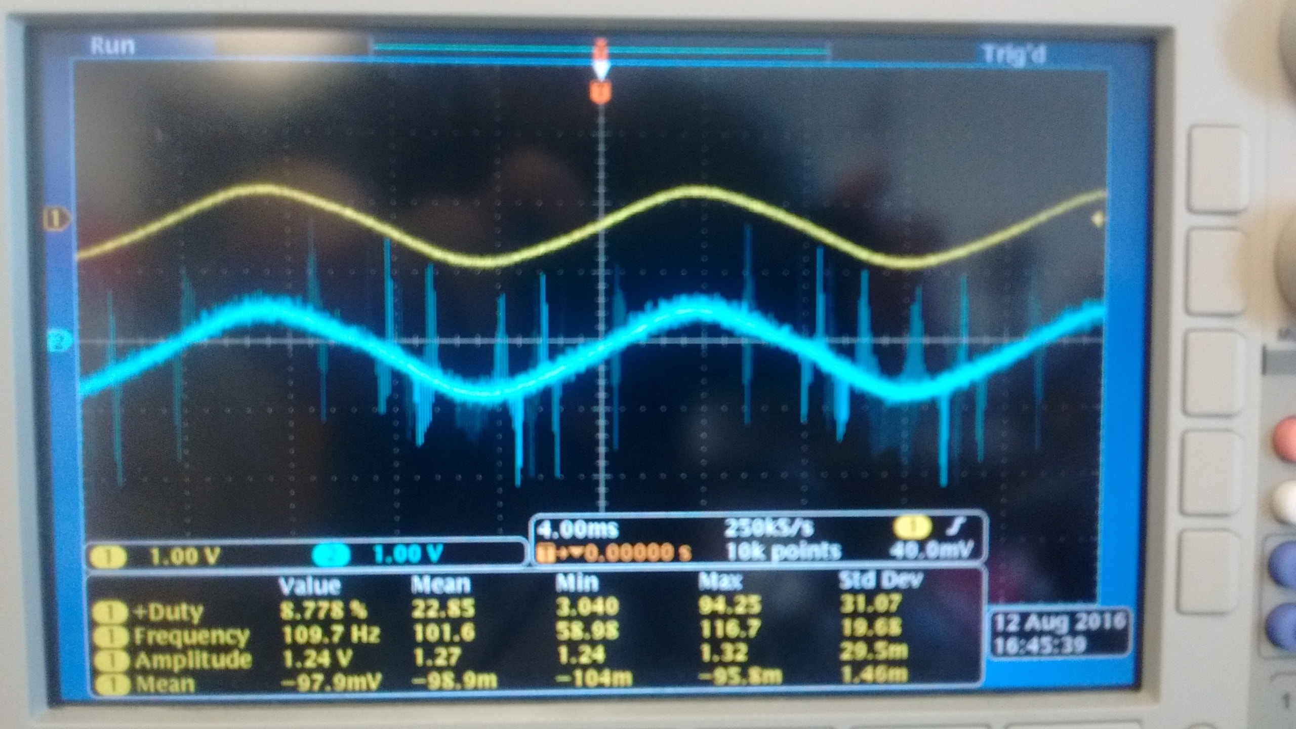
I currently use a NI 9215 module with BNC terminals to read the outputs of two different types of voltage sensors. Probe is a probe differential o-scope (Tektronix P5200A) which has a rejection of sound very good, while sensor B is a shunt isolated hall effect measurement using a LEM lv20-P and a custom PCB, which has a considerably lower noise rejection. Noise in the circuit to be measured is mainly the result of a H-bridge Inverter circuit that goes to 10 kHz. A picture of two sensors measuring the same signal displayed an o-scope is shown below with the sensor signal on top and B sensor on the bottom.
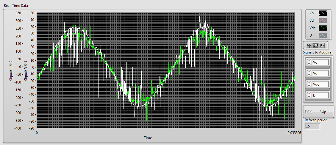
As you can see there is a lot of noise in the B sensor while sensor A is most often silent. When I connect then both of these signals to my NI 9215 I get the signals shown below (75 kHz sampling rate), sensor A appears in white and green B sensor (ignore the differences in scale, it's programmatically).
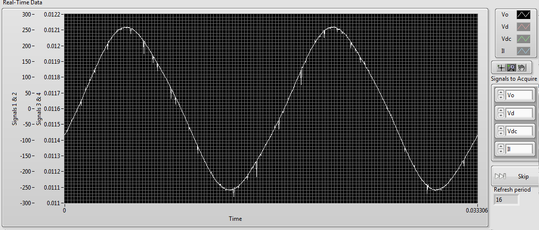
As you can see the noise level in the two now is comparably high. However if disconnect us the 9215 B, the signal from the probe sensor then replaces the image below:Although there are some present noise, the signal is much cleaner than before. The natural conclusion that I draw from this is that there is significant interference between the two signals. The same wiring is used for connecting to the 9215 as o-scope, and the two sensors use shielded twisted pair cables. This amount of crosstalk seems very high compared to the - 80dB listed in the specifications of the 9215. Any ideas what could be the cause, or how to fix it? Unfortunately, I am currently unable to afford a second sensor A.
1. by the impulses of the runt, I was meaning extremely short pulses on A sensor. If they are short enough, you will not see them unless you are looking for.
2. my concern is whether the switching noise is contaminant entering your power supply through the electric wiring. Of course, good feeds should filter this point, but it's just another thing to check.
3. the quick and dirty way would be to use a BNC T-connector to connect the oscilloscope and the ground in this way.
Suggestion of ferrite chokes on instrumentation Henrik is a good.
I understand that this type of inverter using the load (normally three-phase current motor alternative) to filter the frequency of bridge (10 kHz in your case) to the required frequency (normally 50 - 60 Hz). This means that high frequency currents go all the way to the motor, if they are not filtered by the cables first. You can not just screen the housing of the inverter, because the currents of high frequency down to load part of its operation. If you start testing things, you will all the way from the inverter to the load of the screen and will be impossible to Rodez to meet your instrumentation.
Standard WARNING: If you are tempted to connect directly to the UPS output and reduce until the input voltage range 9215: first of all, make sure that a qualified person has verified your wiring. Second place of fuses in all lines near where the tension is taken offshore. A UPS maybe a current loophole in the beach A 100 and you don't want that to the bottom of your wiring of instrumentation. Not directly relevant to your ad, but I feel that I specify.
-
How to acquire the signal to very high sampling frequency
Hello world
My name is Luke Ho. I am trying to acquire the signal with Labview (Sthelescope). The signal comes from sensor acoustics, then filters and amplifiers to adapt to ADC rank (0 - 5V). Thus, the maximum frequency of the signal is 40 kHz.
According to the Nyquist theorem, I sampled at least 80 Khz signal.
Is there a sampling frequency devices like that? or y at - it another way of better? I used the Arduino before, but it was about 10 kHz.
I need your advice.
Thank you all and have a nice day.holucbme wrote:
Thanks for your recommendation
But is it possible without USB Data Acquisition, it is quite expensive for me.
This is the cheapest option to NEITHER. I tried to look for options to other companies, but more I found in the same price range, or not answering is not your condition of sample rate.
-
acceleration of bench of suspension travel active
my application is a project of active suspension, I need to measure acceleration and integration of two to get the position of an accelerometer sensor.
I found a lot of codes, it only works in simulation, but it does not work when I connect it on the acceleration sensor.
I know that I should remove a CC of the speed signal lag after the integration, but it is not clear how we do.
I know that there are many types of integration features in Labview. which of them I should use.
My accelerometer is ADXL335
http://www.analog.com/static/imported-files/data_sheets/ADXL335.PDF
Whenever you perform an integration, your result is an arbitrary constant added to what is essentially your starting value. You have acceleration data. If you integrate this, you get the speed, but you will need to add the initial speed to this to get the actual speeds. When you integrate the second time, you get the positions, but you need to add the starting position for this to get real jobs. So the constants you add will depend on your actual starting conditions (do not forget that the calculation was invented by Newton to describe physics
).I usually use Simpon rule for numerical integration, but if you are sensitive to performance, you can use the digital trapezoid rule or rectangle integration. Before you do anything, you should probably read on them. The Wikipedia article gives a good overview, but the chapter 4 of the book online Numerical Recipes will give you a much better appreciation for the subject. Most of these methods of integration is available natively in LabVIEW, so you don't have to write them yourself.
-
Photon counting using the FPGA of the series R. problem generation TTL signals
Greetings,
I try to use the R series FPGA to read and count the pulses TTL of a discriminator (count of photons of the Hamamatsu C9744 unit) connected to a PMT (Hamamatsu-H7422P-40). The release of PMT looks fine (signal.png H7422P-40) but the discriminator wasn't able to generate corresponding TTL 5V pulse. There was some scattered and random spikes, but nothing significant. Instead, the only stable the PMT signal is a single + 5V pulse no matter how, I adjusted the PMT (C9744 output.png) control voltage. The PMT and the discriminator is connected by an ordinary BNC cable 50 ohms.
I am really confused because it was supposed to be a really simple installation. Anyone have a similar question or have similar Instrumentation (but no problem) configuration? Comments/suggestions are greatly appreciated.
Thank you very much in advance!
Hi Kelli,
Thanks for your help. Sorry it took so long to get back to you.
I actually found the question. The discrimination of the Hamamatsu unit level is set too high that all signals got filtered. After adjustment of the threshold of manuallyt, I was able to get the camera TTL pulses. And 7842R worked correctly for count impulses. Everything works fine now. Thanks again for the input.
-
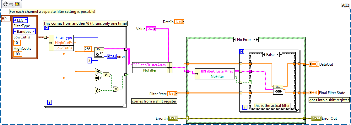
filter init/cont for an option several signals
Hello
I have a table 2D with signals from a device of data acquisition, now I want to do a high-pass and low-pass filter for all signals, and each signal can have it's own high and low pass filter settings, and I can have any number of signals. When I connect my 2D array in a loop and place a filter inside with the init/cont option to true, it resets every loop pass. When I extracted a single signal and pass through the filter it works fine. But this isn't what I want, I want to have signals more filtered in different ways. I think I understand why he restarts, in the help file for the filter it is said: If set to TRUE, init/cont LabVIEW Initializes internal States for the final States of the previous call to this instance of this VI. So that means that each RollBar to pass, there are different data but the same instance... I wish I had different instances for each (for loop) switch. Records snippets of code and its results:
Any ideas?
Best regards
Thijs
Hello
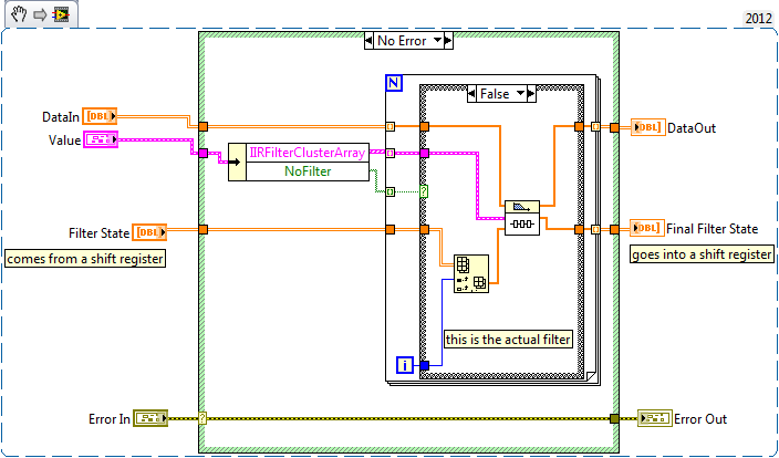
I already solved!
See VI
The FilterState must be initialized, or else the forloop does not work...:
Maybe you are looking for
-
Favorites & Safari on Horiz. iPhone?
I love my iPhone (iOS 9.3.4) 6s but using Safari with it turned horizontal is a waste of time! I turn to facilitate the reading of the text on the screen "large", but for some time when I do this I get a mosquito net for Safari, the other half of my
-
Address bar does not work. Will not open search or site Web open, even when I click on addresses in the menu drop-down. I tried to start in safe mode and I tried Firefox refreshing. I even tried to reinstall Firefox. Any suggestions?
-
Everytime I open firefox, a Web site "plugin check" opens. I thought that once I installed and updated all relevant updates for plugins, the site would disappear when I re-opened Firefox. However, the custom of the page "seem to disappear. I did ever
-
Model battery PA3395U-1BRS for Satellite M30X
Can someone advise the best place to buy a spare battery? There is little available on eBay for about £30, but one thing that I'm not sure... My current battery (supplied with mobile new) States that it is "14.8V 1430 mAh. But all the ones I saw for
-
Pavilion DV6: screen brightness
My pavilion dv6 screen became a minimum of brightness and buttons has no effect (the screen remains dimm) after the restore point prior to rstore it will recover, but after 2 days, it will be dimm, again, maybe an update is the reason why, but an upd