Acquisition continues two sensors LVDT
I'm trying to build a program to monitor the two LVDT sensors inside a table of machining to measure vibrations. I wish I could acquire as close as possible continuous. I'm looking for small delays because the plan is to have a feedback mechanism later and this would require very fast reaction.
I have some experience with labview but am quite new to the use of the structures of the queue. I have done wrong data in a type that I can work with. How can remove my waveform data and use it to perform calculations on the frequency and amplitude?
And by the way, I implement the queue correctly? or does anyone have recommendations to my disposal vi and architecture?
Thank you very much for your help.
I'm using labview 8, but I have access on other computers to labview 9.
-Arthur J.
In the original VI you posted you do not do anything with the data in the queue. You preview the queue and then nothing connect to the wire.
1. use Dequeue. This removes the oldest element from the queue and makes it available. Overview examines the data without deleting the queue.
2 do something with the data. I looks like you can split the four-channel LVDT and places the data in the shift registers. Do you need to initialize the shift registers or do you want that perform the data from the old stored and used in the next series? It is usually best to initialize arrays to the maximum size that you want, and then use replace element of array located inside the loop. This avoids the reallocation of memory.
3. review the appropriate data structure. You start by buying a table of waveforms. After the filter, you have dynamic data. You use in the loop of another tables 1 d of doubles. If you haven't since the waveforms calendar information, try to get data from the reading of data acquisition in a table of double and stay with this type of data overall.
4. consider to put the filter in the lower loop. Usually a producer/consumer that architecture acquired only data in the loop producer and all analyses in the loop of the consumer.
5. as someone pointed out before you need not the structure of the sequence. Data flow will take care of that. You must connect the terminal nodes Visible property error loops below to apply the desired sequence. Use a control with a blank label is OK, but if you have two of them how do you know which is set Visible? It is better to give each control and seeing a unique label. If you don't want the user to see the label, check the invisible label or use a legend or both.
Lynn
Tags: NI Software
Similar Questions
-
reading two sensors (alternately) in a structure of the event permanently
Hello
I have a structure of event with various functions of the user interface. The entire application is on a laser diode control and playback of two light sensors IR which cover different wavelengths (if and InGaAs). The two sensors are connected to the same AD converter, but to different channels. So if I want to read the two sensors, I have to change the setting of the "Converter" AD channels. The real question is how to implement playback continues two sensors in the structure of the event? I want to be able to read alternately each sensor in a span of 50 or 100 m is possible, another using function of time-out of the structure of the event with a kind of logic xor for switching channels? Maybe something with more features (somehow by a timed loop)?
Any idea is welcome.
Thank you and best regards,
Gregor first
P.s. The sensor reading is done by a National Instruments SPI map where SPI is the master.
2010 VI converted down
-
How to synchronize the start of the acquisition of two cards of different daq hardware
Hello
I'm running a continuous acquisition with a PCI-6133 (@2,5. MECH / s per channel, 8 channels) and a PCI-6259 (@250 ksps / sec per channel, channel 3). Both performed in the same loop. The raw data from the data acquisition boards are written in a separate file PDM. Because the sampling frequency of the 6133 is 10 times higher than 6259, each loop, the number of values read from the 6133 is 10 times higher than 6259. If I look in the tdms file, I see the two acquisitions does not begin at the same time.
timestamp of the acquisition
PCI-6259: 02.06.2016 13:09:14, 866
PCI-6133: 02.06.2016 13:09:14, 941
Also, the number of samples of the 6133 is not 10 times higher.
number of samples
PCI-6259: 4949658
PCI-6133: 49309378
questions
-How can I synchronize the beginning of acquisition? Are there some tutorials?
-What could be the reason why the erroneous report of samples (should be 10 between the daq cards)?
Thank you very much.
Michael
Hello Michael,
the beginning of the acquisition can't at the same time as you do not use a common trigger. If you adjust for the different start time, the difference in the number of samples is only about 300 samples (0, 075 s difference at the beginning of the acquisition, which amounts to 187500 samples).
This difference of 300 samples occurs because the schedules of the 2 cards are not synchronized.
If you want to synchronize the starting and the acquisition between 2 cards, you need to connect with a cable RTSI. In this way, you can route the 1 device to another sample clock. The delivery of the sample through the RTSI cable clock is done automatically by the DAQmx driver.
You can get more information in this section of documentation: http://www.ni.com/product-documentation/4322/en/#toc9
-
Need help to set up an acquisition of two channels using NI5154
Hello experts NOR:
I'm setting up a scanner high speed data acquisition NI5154. I have two data channels need to be measured. In fact only the waveforms in the channel 1 must be recorded and channel 0 is used for counting digital pulses.
My goal is like this: once started, the digitizer should count the digital pulses in channel 0 for some time until a start trigger happened in the channel PFI_0. After receipt of the beginning in the channel PFI_0 relaxation the digitizer should switch to channel 1 and start captured signals and save them to the disc. After a well-defined time, stop digitier the acquisition in channel 1 and then switch to channel 0 and repeat as cycles.
my questions are: what the best way to count the Digital pulse channel 0 ? The only way I know is the source of reference on channel 0 command and then get the number of "Done Records" from the property node. After the acquisition of the digitizer will be waiting for the trigger to start in the channel PFI_0, no pulse in the channel 0 will be counted. If I let the impulses in channel 0 not counted in the first cycle, at the end of each cycle how can I switch from channel 1 channel 0 and saitch return after receiving the trigger from the beginning? It seems that I have to configure the trigger repeatly system.
-
Question about the Acquisition continues through NOR-DAQmx
I'm a bit new to NIDAQmx methodology and I was wondering if someone could could give me some advice on accelerating certain measures of tension that I do with a case of DAQ NI USB-6363.
I have a python script that controls and takes measurements with a few pieces of equipment of laboratory by GPIB and also takes measurements in the area of DAQ OR DAQmx via (I use a library wrapper called pylibdaqmx that interfaces with the libraries C native). As I do with the data acquisition unit is 32 k samples at 2 MHz with a differential pair to AI0. An example of code that performs this operation is:
from nidaqmx import AnalogInputTask

# set up task & input channeltask = AnalogInputTask()
task.create_voltage_channel(phys_channel='Dev1/ai0', terminal='diff',       min_val=0., max_val=5.)
task.configure_timing_sample_clock(rate=2e6, sample_mode='finite',
      samples_per_channel=32000)

for i in range(number_of_loops):  < ... set up/adjust instruments ... >  task.start()  # returns an array of 32k float64 samples  # (same as DAQmxReadAnalogF64 in the C API)  data = task.read(32000)  task.stop()  < ... process data ... >

# clear task, release resourcestask.clear()del task< ... etc ... >
The code works fine and I can all the 32 k spot samples, but if I want to repeat this step several times in a loop, I start and stop the job every time, which takes some time and is really slow down my overall measure.
I thought that maybe there is a way to speed up by configuring the task for continuous sample mode and just read from the channel when I want the data, but when I configure the sample for the continuous mode clock and you issue the command of reading, NOR-DAQmx gives me an error saying that the samples are no longer available , and I need to slow the rate of acquisition or increase the size of the buffer. (I'm guessing the API wants to shoot the first 32 k samples in the buffer zone, but they have already been replaced at the time wherever I can playback control).
What I wonder is: How can I configure the task to make the box DAQ acquire samples continuously, but give me only the last 32 samples buffer on demand k? Looks like I'm missing something basic here, maybe some kind of trigger that I need to put in place before reading? It doesn't seem like it should be hard to do, but as I said, I'm kinda a newbie to this.
I understand the implementation of python that I use is not something that is supported by NEITHER, but if someone could give me some examples of how to perform a measure like this in LabView or C (or any other ideas you have to accelerate such action), I can test in these environments and to implement on my own with python.
Thanks in advance!
Toki
This is something I do a bit, but I can only describe how I would do it in LabVIEW - I'm no help on the details of the C function prototypes or the python wrapper.
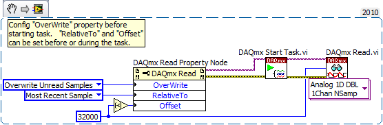
In LabVIEW, there are accessed via the 'DAQmx Read property node' properties that help to implement. One is the Mode "crush" which I'm sure must be set before performing the operation. The other pair is known as "RelativeTo" and "Offset" and they allow you to specify what part of the CQI data buffer to read data from. If you the config to "RelativeTo" = 'most recent sample' and 'Offset' =-32000, then whenever you read 32000 samples, they are the very latest 32000 which are already available in the buffer of data acq. Between the readings, the task is free to overwrite the old data indefinitely.
Note that you will need to do this continuous sampling mode and that you can explicitly set a buffer size smaller than the default which will choose DAQmx based on your fast sampling rate.
An excerpt from LV 2010:
-Kevin P
-
DAQmx: set up a digital acquisition continues with start and stop trigger
Hi all
I write because I can not find a solution to my problem.
As written in the title, I just want to do an continuous (continuous sampling) a digital line. The fact that it's a digital line instead of an analog is no big deal, I guess. I want to start the acquisition on a rising edge of digital trigger (PFI0 for example) and stop acquisition on a trigger too (forehead down on the same signal (PFI0 even then) or a new front amount). This way I could precisely control the time of acquisition or of the start or stop other devices.
Since this is a digital acquisition, you need to do first "something": create a fictitious analog input task and get the clock back to the digital input. I setting this analogue of the task to start on a trigger. It works but I can't find a way to stop it on another trigger.
Do u hav no idea how to implement it?
Finally I have not found an easy way to break cautiously the VI to wait for a trigger (in case you want to start an acquisition with different settings for example). Do you use the task to Abort or is it better to set a deadline to playback digital channel VI until the outbreak occurs?
Any help would be appreciated!
Thank you
Config: LV 2010, latest version Daqmx and USB card or 6251.
Hi Chris,
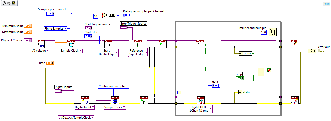
One way is to use counters as Kevin described. For me, it's usually easier to create the dummy task that has the timing engine (as I HAVE), but it depends on what resource you have on your board you will not need
 .
.In fact, the example is the same thing that you need to measure continues - just what you need to do is remove the counter part and replace the trigger reference to be external (your stop trigger).
with this approach, you should be able to do the continuous measurement - I noticed that you need DI - in fact with few changes you should be able to use this example. DI does not have its own timing engine, that's why you should use the external sample clock. If we use the example to create dummy HAVE to provide the sample clock, and we start DI task until we start to HAVE fake, then we can get pretty much continuous clock which begins start trigger and stop the trigger of reference.
Take a look in the change - once again, I have not tested, but logic seems to be OK.
with sincere friendships.
s9ali
-
Acquisition continues using NOR-traditional DAQ
Hi all
For a new project, I have to use an old capture card, a PCI 4451 DSA. I LV 4.4.1 8.5 and MAX, so I had to install the 'Toolkit' for the traditional NI_DAQ.
Usually I use DAQmx screws, so I'm a bit lost with this screw...
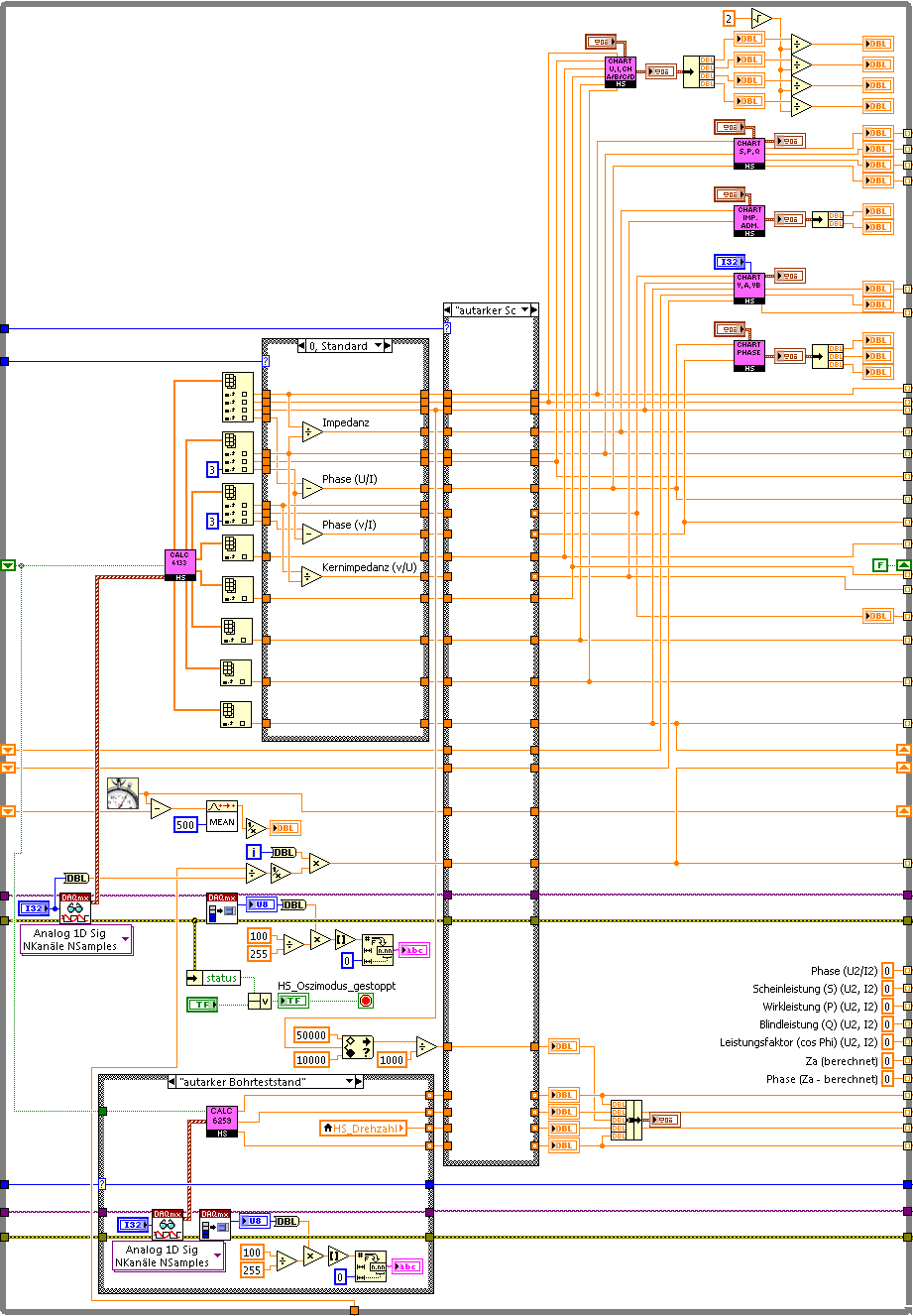
What I want to do is continuous acquisition (see image).
Thank you for your help and I hope that we will find a solution. Thanks for sharing your experience with me.
Marc
Hello
check the attachment and try this...
-
Hello
I am having trouble with the NI 9236 module data acquisition in the cDAQ Chassis 9188. The problems are:
-Noise filtering
-Recording of data
I want to acquire 4 channels with a sampling frequency of 20 to 25 Hz. However, since I have noise problems, I gain with a frequency of 1000 Hz and then the average of the last 50 values. I also change the strain in microstrains.
This program also saves the zero value and uses them to subtract all the additional readings. The entire program runs in a while loop with a wait of 20 ms.
When I simulate the module everythings works fine and I get a nice sine wave of four entries. However, when you work with real hardware I get something like this:
20:59:59.00 NaN NaN NaN NaN
2302 1727 2326 1734 16:18:06.13
2304 1728 2329 1735 16:18:06.32
20:59:59.00 NaN NaN NaN NaN
... x 10where the two readings are followed by 10 "NaN". This could be a problem of buffer?
I appreciate your help.
PS. Sorry for the unnecessary formatting code.
Software of NEITHER: LabVIEW 2010
Materials: cDAQ 9188, NI 9236
Driver version: last
OS: Windows XPHi gmonjo,
In fact, in the code you've sent, did you not the number of samples to be read. It is possible that you are having the same problem with a different error.
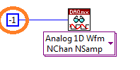
Below you can see the entry where you set the number of samples.
Please, test your VI configure it in order to acquire a constant number of samples of each iteration.
Kind regards
-
How to stop an acquisition continues in producer/consumer
Hello
I'm trying to use producer/consumer to control 'Start' and 'Stop' to my continuous data acquisition system. I can start the acquisition process successfully, but I can't stop it botton 'Stop '.
I enclose my simplified VI. Can anyone help to have a look and tell me what is the problem here?
Thank you
Bing
As I said before, use a notification utility and manage the expiration time. I used a select statement with timeout? Optional Boolean. If a time-out of events, use the previous value. If we got a notification, use this value.

-
Data before release for NOR-6133 trigger material and acquisition continue?
I use the pxi of NOR-6133 can acquire data on 7 channels continuously with ai0 as the trigger without problems. The acquisition is triggered. What I have to do is collect a finite amount of data before triggering immediately until the trigger is detected.
Is it possible to do without the help of a software solution. I watched go over acquisition and using the integrated trigger reference but that is not suitable for my needs because it just seems to change the first section of data to be 'post trigger' to 'pre trigger.
A software solution that I already know how to do is the last resort to try to reduce the demand for processor and keep the hardware triggering.
Thank you
By using the "reference trigger" is the right solution.
So can you please explain a little more in detail why it does not work in your case?
Christian
-
Selection of the range of Gain on the acquisition continues
I develop on the OEM version of 6211. We use all 16 channels to HAVE it. Is there a way to change the gain of a channel range without having to stop and restart the task because this causes a discontiuity in the data?
In the case where there is perhaps not a smart collection I can use there. I use channels 0-3 for readings of voltage and 4-15 to the current readings, with each group of 3 current readings must be synchronous with time pressure readings. For example, 0-4 and 4-6 would be composed of a data set and 0-3 and 8-10 would be another.
If I create a separate task for each grouping the power would be so disruptive. If I start one task that she buys 0,1,2,3, another who acquires the 4,5,6 and another who acquires the 7,8,9 is 0,1,2,3 and 7,8,9 channels still synchronous time (assuming that this task niether has not been stopped and restarted)?
Hi Matt,
Just a follow-up, we are limited to one task for analog input on the 6211. All our channels HAVE will have to be in this task. This is due to the timing engine shared used in the device and the multiplexer which runs the channels.
Kind regards
John Sullivan
Technical sales engineer
National Instruments -
How can I make graph waveform or file with two different values of DBL Dynamics excel?
As described in the question, I have two sources dbl from a load cell and linear actuator (from remote). I want to do a curve of load/displacement of the readings of the strength of the load cell and the readings of travel of the linear actuator. Load cell generates an analog signal that can be acquired by data acquisition and the actuator is delivered with a Board and a program of VI to control speed and measure the movement of the actuator at a sampling frequency of my choice. Is it possible that I can do a VI where he continues to collect data and build the chart I'm looking for?
I think I see where the confusion is. Looks like your trip data do not come directly from a sensor (LVDT, etc.), but from the control software. If this is the case, you're stuck sort with a timing of software, that will not sync at all. Still not really sure what the entire Setup is - but if you do not have access to data of travel other than VI control that drives the actuator, you have limited options. It depends on where these data comes from and how it is treated. My initial comment assumed medium of moving a sensor in another Board (Non-OR).
You can absolutely use a shift register data (or the node property history given in the table of waveform - as someone else suggested) to save the data in the file. Use the entry in the File.vi worksheet. There are examples that show how to do this.
I would start by trying to start the process (movement and data acquisition) as close to simultaneously as possible, let them operate independently, but at the same time, then after you have some data you can see if they are synchornized well enough for your application. If you put them both in the same loop with while avoiding (wait ms) you will get incoherently timed data of these two sets of data. Better to use examples of hardware when clock you can. If your test article moves very slowly, it may not matter how you do it. If it does not quickly move, will be discussed as your data of force tip line upward with your data points in moving closer in time.
Good luck!
Kurt
-
motor continuous: what are the step to build a controller
Hello
I hava a motor continuous with sensor position and data acquisition
I want to control '' position' ' of this method of dc motor using state space in labview
can someone give me the step what can I do to implement this controller?
I wheel a lot of article but I'm confude of where to start
Best regards
Magnin
See answer in:
http://forums.NI.com/T5/LabVIEW/DC-motor-speed-control-using-LQR-controller/m-p/2359316#M735694
-
Two DMA FIFO fill and asynchronous playback?
Hello
I work lately on the Labview for my system which includes the acquisition of data from two sensors in FPGA vi and communicate to RT vi, where I treat the two sensor data and subtract. I am facing a problem of synchronization. I tried 4 data points, 2 of each sensor to each 25th microsec. Here I attach a pseudo-code that is just one of my original code that shows the same problem.
When we run the code, acquire US 4 data points each 25 microsecs in the FPGA vi and storing in the fifo DMA 2.
Then, I read this in RT vi and display them.
When I have a single loop in the FPGA and RT vi. the number of elements left in the two fifo should be identical, I perceive.
But in this case, it is not. Please enlighten me why?
Concerning

Intaris is right. How work DMA FIFO is that they fill a small pad on the FPGA, and when this buffer is almost full, the data is copied (automatically and at the bottom) of a larger buffer in the memory of the host. The remaining items is the amount of data is left in the buffer of the host. The automatic copy of the FPGA to the host will happen precisely at the same time to the two FIFOs, so you will get different amounts of data in each. The total number of items (between the pads FPGA and host) should be the same, although there is no way to see that, except for read all data (until the two buffers are empty) and confirm that the total number of items of reading was the same.
-
Sensors of e/s digital or analog?
Hello
I worked on a project and requires the use of 3 piezoelectric sensors (listed below). which 2 are vibration sensors and the other a force sensor. No one in my group are at all familiar with electronics or circuits, and the 'majors' EE we talked talked way over our heads. Anyway they gave us a basic way to implement two sensors to the analog inputs, and they said we can do only two sensors because there are not enough entries. For some reason, I think it can handle more than two sensors. I know we use analog i/o, but is there anyway to use the digital I/o, which have many more ports? We also use a Breadboard to connect the sensors. And after two EE majors left we tried using the force sensor that worked, then we used the sensor of vibration with the same set up and it did not work. ALL the information would help us! (we were also given a small budget too)
http://www.SparkFun.com/products/9376
http://www.SparkFun.com/products/9196
Hey Jake,
If you go to the product page for the myDAQ and click the specifications tab, you can see that there entry 2 analog and 2 analog output channels. For example, you can use only 2 analog sensors with this device. You can either buy more myDAQs to increase the number of channels or switch to another card with more channels low-cost DAQ HAVE, such as the USB-6008. Please keep in mind that the myDAQ is not intended for practical use, only for educational purposes.
Finally, if you choose to continue using the myDAQ with your piezoelectrics, please keep in mind that this specific device is supported in the material for teaching product forum.
Thank you
Lisa
Maybe you are looking for
-
For example: I could type 'facebook' in the address bar and it would automatically take me to facebook.com now he takes me to google.com and shows me the search results. I want that Firefox take me directly to the page as before I installed Firefox 4
-
Noisy fan on Satellite Pro L830
Hello for two days, I had new laptop Toshiba L830. Windows 7, 64 bit - RAM 4 GB system. Fan is noisy. He gives sounds. What can I do to get rid of this noise? There is no dust in the new laptop and I work in the House. Fan noise irritate me. Processo
-
Lines orange once highlighted?
So this is probably a stupid question, since I don't use animate for too long.Can someone explain why once I highlighted a part of a character that I drew, it selects instantly the part that I have put in evidence, but on the contrary shows my stroke
-
Evaluation period for the stage of field custom object compare?
I've never used an evaluation period during a stage of field of the custom object to compare on the canvas of the campaign and I want to confirm that she will be as I wait for him.We have a campaign that will send an email in nine batches, each a wee
-
Can not do the ping test with to assign a VF SR - IOV for an operating system called window 2008.
HelloI am very confused on below question:When I using a 2008 guest operating system window, can't do the test of ping with a pc.But if I'm using a linux guest OS, it doesn't.NIC: x 540 - at2ESXi:5.5 u2Steps to follow:1. install ESXI.2. create VFs an