Acquisition of data NOR-9205 Assistant set up range of input voltage
How to configure the module NI9205 to use the +/-200mV input range.
I use a custom scale, and it seems that I can not get an accurate reading. I use a shunt current of 100 Ma (max 10A). So I custom balance setting to have 100 x + b. The current flowing in the device is 2 amps and I get a reading of 12-13 amps after custom scale. Now I think the module is configured to sample for the entrance of 10V and I get an error of resolution.
Hi therbert
Since your custom scale is 100 x, to work on the beach of +/-200 mV to your NI 9205 module you must configure your input signal of maximum and minimum range for +/-20 respectively.
According to the equation: Range.max * scale.slope = 200mV * 100 = 20V
This will automatically configure to the scope of the module +/-200 mV to verify you can access the channel DAQmx property node and look for the analog input > General Properties > advanced > Range property, this will let you know in what range is the functioning of the device.
Concerning
Tags: NI Software
Similar Questions
-
Acquisition of data NOR usb 6008: a strange problem: mxwcgoutrunsilent.VI is not respected
Expensive OR
Today, I bought an acquisition of data NOR usb 6008
and I'm using labview in 2011
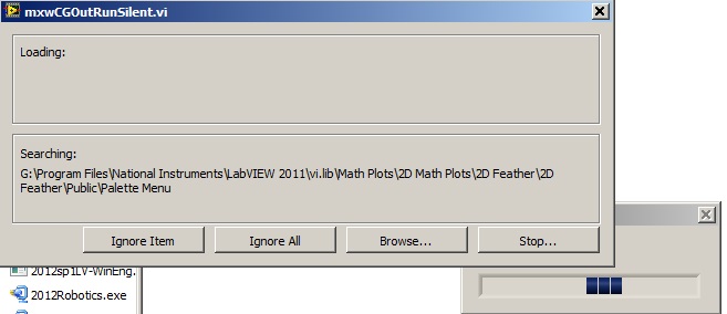
the problem is appear when after I end the process of configuration of the i/o data acquisition Wizardthe following image shows the mxwcgoutrunsilent.VI is ignored and an error has occurred
someone can help provide this VI for me
What is the complete labview modules can also so I could do a real time data acquisition
Best regards
mangood,
You received an error code? If so, what is it? What version of NOR-DAQmx driver you have installed? It seems your driver potentially incorrectly installed, and you may need to reinstall the driver.
Here is the link to the latest version of the NOR-DAQmx driver: http://www.ni.com/download/ni-daqmx-9.8/4297/en/
-
ACQUISITION OF DATA NOR USB-6251
is it possible for the box USB-6251 to provide an output for a test set-up during playback of the inputs of the device even? for example: 10VAC Ridge to Ridge on the luminaire, mixed the sine and square wave signals of the luminaire to the data acquisition Toolbox.
Yes. The 6251 has two outputs analog and 16 analog inputs. Open finder example and looking for examples of both. Under input and output hardware > DAQmx > Syncronization > multifunctional, it is an example of analog inputs/outputs synched.
-
Simultaneous to the AO and HAVE with the acquisition of data NOR USB 6001/MATLAB Toolbox
I am very new to data acquisition and bought a NI USB 6001 to start to learn. Because I can get free MATLAB through my University, I use Matlab data acquisition Toolkit as the data acquisition software.
My problem is that I get the following error message when I try to generate an AO (an LED voltage) signal and measure a signal I (voltage of a battery of 9V) simultaneously.
ATTENTION: This change is caused in the dump output data queue. Use queueOutputData for the queue data before the start of the object.
Hardware does not support the specified connection. Check the user manual of the device for the valid device routes and pinout.However to measure IA or by generating the AO each by themselves works perfectly well.
My Matlab script looks like this:
daq.getDevices;
s = DAQ.createSession ('or');
s.Rate = 1000;
s.DurationInSeconds = 10;
addAnalogInputChannel (s, 'Dev1', 'ai0', 'Voltage');
addAnalogOutputChannel (s, 'Dev1', 'ao0', 'Voltage');
aoVoltage = 1.8 + 0.1 * sin (linspace (0, 2 * pi, 10000))';
queueOutputData (s, aoVoltage);
s
startBackground (s);
Note that adding the channels HAVE and AO at the session also works, however I get the error mentioned at the start of the session. This is a limitation of my data acquisition hardware (I don't see something like that mentioned in the manual) or do I have to modify the script?
The pins connected for the LED are AO0 (+) and AO GND (-).
The pins connected to the battery are AI0 (+) and (-) AI4. (The problem is still there if I use the reference to the ground for AI)
6001 cannot make simultaneous tasks. Very standard limitation of the low-end hardware... just don't have on board computing resources to handle such things. Even the 621 x boards have only limited multitasking abilities.
Can intensify to a high range data acquisition ($$$) or buy a 2nd a low end and synchronize tasks in software (not as precise calendar). I've done two approaches, one is "best" really depends on demand... If low-cost or high-performance is a priority.
-
My acquisition of data NOR usb-6008, does not appear in labview after installing drivers
My DAQ does not appear in my labview program after installing the drivers. I can't add it to my program or anything like that. I installed 3 different drivers and updates, and it's still not appearing in labview. Is there something I'm missing or need to do yet?
Thank you
It seems that you have a damaged file somewhere in your installation. You will need to go into the control panel and select the option to repair the installation. You will need to run the repair twice due to a known problem. After that, you need to reinstall the NI_Daqmx 9.4.
Jacob K
-
Here is my sensor
Pressure sensorHere's the DAQ data sheet:
Here are my issues:
First of all I don't know what is LO and HI exactly in the DAQ 9219 material.
Second, I don't know what pin code I should connect the DAQ sensor signal wire. PIN 4 or 5 pin? The sensor has three pins, and I guess I should connect the other two wires to the power supply.
Thirdly how to calibrate the sensor. In labview choose voltage in the wizard?I'm pretty new in this acquisition of data and I need your help.
Thank you
Hi SilasIII,
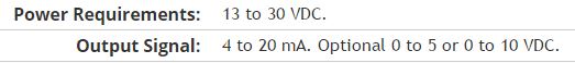
Hmm well 3 sons are probably on the ground, the power and the return signal. The datasheet for the sensor says:
First of all, you need to know which model you have (4-20mA, 0 - 5V or 0-10VDC). HI refers to the return signal, LO essentially means the land of the food that feeds the sensor. Then, you must get the 13-30 VDC supply. I don't think this should be too complicated and can be a simple wall DC power. You can learn how to create a custom in DAQmx scale. I hope that this is a starting point.
Kind regards
Eric
-
Acquisition of data from multiple loops
Hello
I tried to adopt a program of data acquisition of multiple loops with control of queue, but it does not work as it should. (Or at least the way I think it should) Could you please help me it smooth? I have seen a few screws on the internet with the queue-control and tried their adoption.
My program should work this way: after you complete the settings, I begin the acquisition of data (an analog output and 2-4 analog inputs), but I only want to save the data acquired when I click on a registration button. (Then these data would go for further analysis). While doing the analysis, the acquisition may be suspended. However, when I click on record I would like to have a feature to instantly restart the recording and to ignore the previously recorded data.
MainProgram vi is the application itself, with some settings made by the event handlers (now only limited to a selection of signal file and the channel settings). Then the data acquisition can be started by clicking on the button start the Acq.
And these are my issues: first, sometimes the queue starts, sometimes is not (or at least it does not start the data acquisition). And the main point: I put the sampling frequency, but it is acquired at a slower pace of well (my signal has a delay of 4 seconds, but he needs at least 20 seconds before getting close to finishing). And the strangest: sometimes, especially after some time (about 1-2 min) it freezes and does nothing with the acquisition of data (yet labview seems sensitive, just my program blocks somewhere).
So now only controlled acquisition is in the problem and firstly I don't like on the transmission data for analysis and recording. (Which seems to be the smallest problem).
What I am doing wrong? Thanks for your help.
I join all the files. (MainProgram is the application itself, MY. SIGNAL is the signal I want to exit.) I use a USB-6211. (for physical work, home a simulated).
Not directly related to your mistakes but (and here I don't mean to take on you, but... With an alias as yours, I assume that you have some sense of humor)
Really? an event structure single image with only one case of timeout (value 1mSec) with a Dequeue inside element
 how do you code would work by simply removing the structure of the event entirely
-
Use two assistants for the acquisition of data at the same time
Hello
I want to read multiple data channels of analog inputs on my DAQ hardware. However, when I try to create two separate data acquisition assistants for each entry, it gives an error saying "is reserved for the specified resource. The operation could not be performed as indicated "." Can't use two assistants for the acquisition of data at the same time?
I have to add different channels in the same assistant DAQ? I tried, but I couldn't separate the data in different graphs.
How does this work?
Kind regards
Allard
You can't have multiple tasks of the same type (in this case inputs analog) on the same device. Just so having 1 DAQ Assistant read all your channels and separate your channels for individual transformation.
-
acquisition of data and processes in FPGA
Hello!
In FPGA, I am trying to acquire analog data (0 ~ 10V) with a specific time clock rising edge of each digital pulse encoder.
I went to get the data on the front, but I don't know how I'd keep th and i + 1 th data.
(Frequency of data is less than 250 kHz)
I have the cRIO-9074, NI 9411 (encode), NOR 9205 (module I),
data
1st, 2nd data, data 3rd 4th 5th 6th 7th... I-1 th, I e, i + 1-th... 1200 e (approx.)
I need every sum of two consecutive data data 1st + 2nd, 2nd + 3rd, 3rd + 4th, l - 1 e + i Thess,... th + (i + 1-th)... 1199 th + 1200 e (about)
On the process of two consecutive sum.
[i - 1 e + i th] / [a value] + [the other i e amount of different data acquisition] = 1199 set of data (up to 1200 th data)
and then
all data across data (data from 1199) will be worth.
Thank you very much!
All tips are welcome!
Sincerely,
Hyo
Looks like a simple feedback node will do the trick.

-
merger acquisition of data to read input data 2 or several at once
Hi all
I'm using or usb-6009 more then 2 incoming signals.
the problem is that I can't read 2 signals at the same time. 1 my daq assistance will be apeared to be error.
so, how can I set the .vi (attached) so that he could read 1 more signal since the acquisition of data?
I also tried to separate daq support but error. I also try to merge the two signals with a different port (a1 and a0)
can anyone help?
Thnx for the reply
Frankly, I went through all the tutorials and looked for answers in the forum and the conclusions I have difficulties to understand the technical language... I have been looking for everywhere labview users and found someone who could guide me carefully... im have desperately need guidance... not to give up hope trying to find the answer, but a sort of feedback that is giving advice that you need to take the driver's seat... FYI... I take the driver's seat... that look like a real Nubian now needs help...
is there any order step by step so that I could add channels more 1 1 daq help?... I've done it before, but it occurs.
for example, I want to create channel 1 to read the value of the resistance and channel 2 for playback of tension... but what happened when I create more than 2 channels, it is be will configure this channel only 1 located in the block diagram... both channal will give only data for the value of the resistance.
Sorry for my broken English.
-
Acquisition of data and filtering on FPGA
Hi all
I have trouble to design a FPGA program for acquisition of data and filtering.
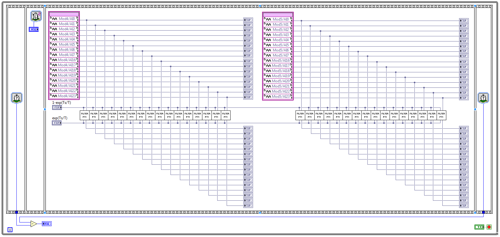
I have two NOR 9205 modules configured to work in terminal mode of DIFF, i.e. There are 32 entries this program must read every Ts seconds. (Ts is the time discretization, i.e. during the period of loop)
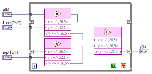
With respect to the digital filter, I implemented a possible simple filter with transfer function G (s) = 1 /(1+sT), which is part of the field of discrete-time equal to y (k) = a * u (k - 1) + b * y (k-1), where u is the original signal, and there is filtered signal. The coefficients a and b are equal to: a = 1-exp(-Ts/T), b = exp(-Ts/T), and T is the time constant of the filter (usually T > 5 * Ts).
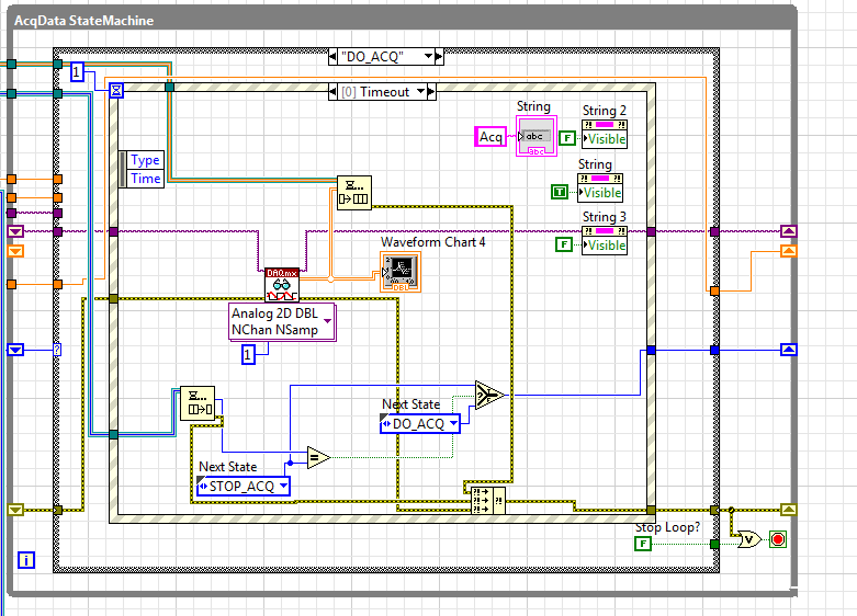
The implementation of main program for the acquisition of data and filtering are:
This application is for the digital filter:
However, the problem is that this program cannot take the FPGA resources on cRIO-9114, and Yes, I tried to define the criteria of compilation for the area. I also tried to implement the multipliers in digital filter as lut and DSP, unfortunately without a bit of luck.
Because I don't have that much experience in programming of FPGA, someone has any suggestions how to improve this code to adapt existing FPGA resources?
Best regards
Marko.
Hey Norbert_B,
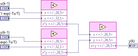
I managed to solve the problem. First, I changed the reentrancy of Preallocated incoming execution clone to not reentrant execution. As no reentrant VIs have States, I had to use the node of the feedback to the main VI to get u(k-1) and y(k-1). Another important thing is to choose Ignore FPGA reset method in the node of the properties of FPGA implementationfeedback, since in this case, the feedback node uses less resources.
Here is the new main program VI:
And here's the 'filter' VI:
Thanks for the help!
Best regards
Marko.
-
Generation and acquisition at the same time, acquisition of data USB-6356
Hello
I have a VI how is able to read entries with a USB DAQ-6356 and I use a generator of signals 'Agilent 33522 A '. I want to generate and acquire with the acquisition of data.
In fact it works but not well, the frequency is not very stable and does not stop the 2nd loop with 1 (2nd is generating, 1 is Acquire).
Thanks in advance
P.S my VI isn't a state machine true because I need to fight against it at the moment.
OK, so you're at 3 ms/s in writing and reading at 1.25Ms / sec and you wonder why he has a little difference in the frequency set? Ideally, you want to read and write to share a sample clock but by selecting at least the same frequency clock (or one that is one multiple of the other) would go a long way to fixing this source of your error.
The second source of error: you generate a contineous waveform. unless you select 'whole number of cycles' there is a discontinuity when the end is reached at an arbitrary phase and the phase is reset to zero at the beginning of the wave. DAQ assistant writing can "Use Waveform Timing" to adapt its sync settings to the dt waveform and the number of samples.
-
Need a new acquisition of data USB multifunction device
Hello
Currently I use a PCIe - 6321 Multifunction DAQ hardware to control my stepper motor. I need to change the PCIe - 6321 and use the engine with a device for the acquisition of data USB multifunction bit PCIe - 6321. I'm not sure which USB model to select. Can I please get help about the choice of the right MIO USB data acquisition device that works similar to the PCIe - 6321.
Thank you
Bharath J S
The 6212 differs from the 6321 somewhat on the digital side, which probably you use to control your stepper motor. For example, it was only software DIO timed tasks and has only 2 counters with a set of features (e.g. no output meter in the buffer).
Best regards
-
Acquisition of data using the DAQ card
Hello everyone
I need assistance with the acquisition of data of the generator of signals through DAQ cards. I plugged the signal to the SCB-68 generator where the analog inputs of the generator are connected to AI CH5 and AIGRND of the Terminal Board. Then the output of the block is connected to the DAQ card. The maximum sampling frequency of the card is of 250 kech. / s. The problem is for reason that I am not able to see the waveform on the labview. I looked at other examples to find the problem, I am, but I am not able to understand this. I want to be able to choose the sampling frequency. I attatched my code as an attatchment for you all to help me know what the problem is. Any suggestions will be appreciated.
There is no task! You have not specified any hardware (i.e. your data acquisition card) anywhere.
Here's a suggestion. MAX aperture. Find your DAQ hardware. Open a Test Panel. Implement a continuous sample of N Points to some sampling rate. Press Run and convince yourself that you get the data.
Now, while remaining in MAX, to create a task, using the same settings. Call for example something sensible ("MyFirstDAQTask" is not a good reputation).
Now, go back to your code. Eliminate the first two functions DAQmx. Wire a constant task to the DAQmx Start feature. See the little triangle down? Click it, and it should show you the tasks he 'sees', the only one should be the task that you created in MAX.
Note that 'Samples Visible' is now 'hard coded' in the task. To get its value back out, you need to put a property node Timing DAQmx after the task start and pull on the quantity of the sample, samples per channel (which, for reasons that escape me, is a Dbl, you need to convert to an I32 before importing it into the while loop).
Bob Schor
P.S. Thank you to join your code.
-
Acquisition of data using C++ and cRIO-9066
Hello!
I want to write a C++ application that would make the acquisition of data from modules installed in the cRIO-9066 chassis and this application should work without LabView. How can I do? This chassis connect to my PC using NI-DAQmx? Is this possible?
Hi aanodin,
When you use a device that uses our architecture of RIO, it is usually best to use LabVIEW to develop your application. In this way, you can also program the FPGA with LabVIEW FPGA module and makes programming much easier real-time processor. In fact, your model of cRIO is officially supported by our LabVIEW programming language, as seen on page 4 of the Manual: (http://www.ni.com/pdf/manuals/376186a.pdf).
Due to the FPGA interface, you cannot use DAQmx with cRIO. I hope this helps.

Maybe you are looking for
-
Game change/iTunes iTunes Store
Hi Fellows! I now live in the United States and tried to change the Brazilian to store US but iTunes does not because I have an iTunes game subscription valid until June/July 2016 and he says that I have to cancel on command to change stores. I can't
-
Hello. You can replace the card wifi b/g - b/g/n? Thank you
-
Extensa 5235 touchpad suddenly fails in win 10
My laptop worked fine on win 10 for a few months now. Suddenly two weeks ago the touchpad stopped working. I tried windows recovery, but it does not work. I tried to update the drivers of Synaptics (19.0.19 versions), no effect. Pick ps/2 touchpad ma
-
Installation/uninstallation of Windows Media Player 11
Hello. I'm a Dell laptop user with windows Vista Home Basic 32-bit. For more than one Media Player window on my computer stopped working. Because I didn't know what to do to remedy this I installed VLC Media Player and was used during the WMP was not
-
Cannot find the downloaded MS office
I have supposedly just download a free trial MS office form, but I don't have it on my computer and yet, what is happening? OT: I have supposedly just download a free trial MS office form, but I don't have it on my computer and yet, what is happening