Adjust the voltage for the acquisition of data in C range
Hello
I'm trying to run a USB-6211 in C++ and I would like to change the voltage range of (-10V to10V) to (-1 v to 1 V). Can I just change the minVal and maxVal in DAQmxBaseCreateAIVoltageChan call? Or I have to adjust the device itself and recalibrate.
Concerning
Simon
Hi Simon,.
Thanks for your post. You're right, you just need to change the minVal and maxVal in the call to DAQmxBaseCreateAIVoltageChan. The DAQmx base driver supports the hardware of the range you select, do not re - calibrate your device to adjust the material.
Kind regards
Tags: NI Hardware
Similar Questions
-
We send 5v data acquisition using a voltage generator. Hook us it up to a voltmeter and see 5V. When connect us the generator voltage to a valve "normally open" parker, the voltmeter indicates .14V. It seems that when we connect the two sons of the valve for the voltage generator, the son act as pattern. We want to control the voltage flowing to tap through Labview. We checked the wires to the valve and they work very well, because if we send a constant 5V since the acquisition of data and put ashore, she, the voltmeter indicates 5V. Someone knows why the son act as pattern and low blood to .14V?
nsatpute wrote:
Our data acquisition is NI USB-6259. The valve requires only a 5V max and our DAQ provides up to 5V. However, after connecting the valve to the acquisition of data, the grave tension to almost 0. We start from the principle that the son somehow act as the reason, but we are not sure if this is the case.
The question here is not how much voltage the valve wants, it's the current needs of the valve. The 6259 can put only 5mA via an analog output. Your very likely tap needs much more than that. If you need to add in an amplifier circuit that can supply more current to operate your faucet.
-
I have a PCI 6519 data acquisition card. I want to install it on the PC and use it outputs to control a robot. I have problems with the connections to the terminal block which is attached to the cable.
What type of connections I do for the acquisition of data PCI 619 card pins? What I have to give it to the ground and the CCV on the pins of the connector myself? What should be the value of the SCR I need to give to the PIN?
-
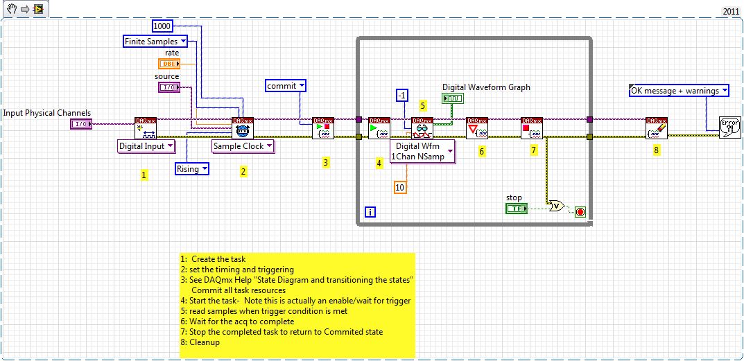
Restarting a task for the acquisition of data inside a For loop
Hello
I need iterate through my acquisition of data. Currently, I'm doing this through the creation, implementation and tasks for the acquisition of data inside a loop For which is iterated according to the needs of compensation. Unfortunately, the creation of these DAQ tasks slow down my code.
I would like to be able to create the tasks outside the loop, pass them in and revive the tasks at the beginning of each iteration. Is there an easy way to do this?
Otherwise, is there a way to make the standard DAQmx digital startup trigger trigger several times (so that it starts each pulse data acquisition in a long pulse rather than just the first pulse train)?
Thank you!
-Evan
I whent before and created this example for you (and many others.)
-
Use two assistants for the acquisition of data at the same time
Hello
I want to read multiple data channels of analog inputs on my DAQ hardware. However, when I try to create two separate data acquisition assistants for each entry, it gives an error saying "is reserved for the specified resource. The operation could not be performed as indicated "." Can't use two assistants for the acquisition of data at the same time?
I have to add different channels in the same assistant DAQ? I tried, but I couldn't separate the data in different graphs.
How does this work?
Kind regards
Allard
You can't have multiple tasks of the same type (in this case inputs analog) on the same device. Just so having 1 DAQ Assistant read all your channels and separate your channels for individual transformation.
-
Read for the acquisition of data entries are overwritten
Hey there
I have a Daq reading input in a spreadsheet file
Data acquisition was told that one is supposed to have some time a loop around it and I cannot get it to run without one, so good
But my main problem is that it means that it replaces my written file each time that the loop repeats
He also asked me to choose the file to write in several times
How would I go about fixing this?
Thank you
Yes, you can convert digital to the chain, check the attached VI. I recommend you to go through the basic materials of LabVIEW and also play with example of NEITHER which comes with LabVIEW. Remember not to use the attached example and the acquisition of data, always use separate loops.
-
Hey Hey everyone
I was looking for an example for two-channel oscilloscope virtual using e/s all-in-one of the 14 bits of NI DAQ USB 6009. I tried to research for example BOF time division or s/div for 1 second, 5 seconds, 10 seconds. but was shocked to find that there is no reference for it. The range of oscilloscoper virtual
Minimum - 10 micro s / div maximum -10milli second div but there is no example for 1 second / div or 5 seconds / div... If anyone can guide me. I'm new to labview environment.
This is the oscilloscope two sample obtained from google search. is there material limitations. ?
I'm working on continuous 4-channel data acquisition data acquisition using niusb 6009
The sampling frequency is sufficient for any desired s/div. The sample rate is 12 ksamples / s per channel, so if that meets the Nyquist criteria for the input signal, you can capture it. The number of samples has no effect on that with the exception of the amount of the signal you acquire. Your chart is not stable, if you do not trigger the acquisition. Even as real significance, therefore your emulation seems actually successful.
-
Hi all... I learn LabVIEW since few days.i want to acquire a signal of pc6251 of acquisition of data and perform fft it can u people please help me? Thanks in advance
If you do only use LabVIEW for a few days, you should get familiar with it first by looking at some of the resources available here. After that, you can watch heredata acquisition.
After reviewing these documents, you can post back with any specific questions.
-
Simultaneous to the AO and HAVE with the acquisition of data NOR USB 6001/MATLAB Toolbox
I am very new to data acquisition and bought a NI USB 6001 to start to learn. Because I can get free MATLAB through my University, I use Matlab data acquisition Toolkit as the data acquisition software.
My problem is that I get the following error message when I try to generate an AO (an LED voltage) signal and measure a signal I (voltage of a battery of 9V) simultaneously.
ATTENTION: This change is caused in the dump output data queue. Use queueOutputData for the queue data before the start of the object.
Hardware does not support the specified connection. Check the user manual of the device for the valid device routes and pinout.However to measure IA or by generating the AO each by themselves works perfectly well.
My Matlab script looks like this:
daq.getDevices;
s = DAQ.createSession ('or');
s.Rate = 1000;
s.DurationInSeconds = 10;
addAnalogInputChannel (s, 'Dev1', 'ai0', 'Voltage');
addAnalogOutputChannel (s, 'Dev1', 'ao0', 'Voltage');
aoVoltage = 1.8 + 0.1 * sin (linspace (0, 2 * pi, 10000))';
queueOutputData (s, aoVoltage);
s
startBackground (s);
Note that adding the channels HAVE and AO at the session also works, however I get the error mentioned at the start of the session. This is a limitation of my data acquisition hardware (I don't see something like that mentioned in the manual) or do I have to modify the script?
The pins connected for the LED are AO0 (+) and AO GND (-).
The pins connected to the battery are AI0 (+) and (-) AI4. (The problem is still there if I use the reference to the ground for AI)
6001 cannot make simultaneous tasks. Very standard limitation of the low-end hardware... just don't have on board computing resources to handle such things. Even the 621 x boards have only limited multitasking abilities.
Can intensify to a high range data acquisition ($$$) or buy a 2nd a low end and synchronize tasks in software (not as precise calendar). I've done two approaches, one is "best" really depends on demand... If low-cost or high-performance is a priority.
-
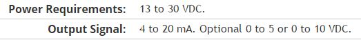
Here is my sensor
Pressure sensorHere's the DAQ data sheet:
Here are my issues:
First of all I don't know what is LO and HI exactly in the DAQ 9219 material.
Second, I don't know what pin code I should connect the DAQ sensor signal wire. PIN 4 or 5 pin? The sensor has three pins, and I guess I should connect the other two wires to the power supply.
Thirdly how to calibrate the sensor. In labview choose voltage in the wizard?I'm pretty new in this acquisition of data and I need your help.
Thank you
Hi SilasIII,
Hmm well 3 sons are probably on the ground, the power and the return signal. The datasheet for the sensor says:
First of all, you need to know which model you have (4-20mA, 0 - 5V or 0-10VDC). HI refers to the return signal, LO essentially means the land of the food that feeds the sensor. Then, you must get the 13-30 VDC supply. I don't think this should be too complicated and can be a simple wall DC power. You can learn how to create a custom in DAQmx scale. I hope that this is a starting point.
Kind regards
Eric
-
temperature sensor with the acquisition of data usb-6009
Greeting
I want to use a sensor with usb-6009 to save the variation of body temperature about 15 minutes and then use these data in labview.
If you please you can advise me with the best low-cost use and the way/circuit sensor connect it to the usb-6009.
Hi ba7soun,
If you can use with USB-6009 LM35 depends on the range of output voltage of the sensor. I understand that it requires a 5V supply with respect to the ground, which you can provide to the USB-6009 (more than 200 my should not come from the USB-6009).
The maximum range of the USB-6009 is - 10V to + 10V, while the minimum range is - 1V to + 1V, also probably the output signal of the LM35 will be in this range. What you need to do is to compare the full range of the output signal with the range of the DAQ divided by 2exp (14) (because it is a 14 bit ADC) and ensure that the first is much more than the latter.
Kind regards
Condette Dhruv.
-
Problem with the acquisition of data on XP Embedded
Hello
I'm using LabView 8.5, 8.7 DAQmx. My application is collection of data of NI USB-6009 14bits. I tried to create applications for tablet PC with installed Windows Xp Embedded. I created the installer on tablet with installed Windows 2000. I solved all the problems that occurs during installation. First version of the program have assistant DAQ in a main VI who collect and process the data. It worked properly on Xp Embedded. Second version was split into two of the Subvi. One is data collection and secondary processing. Each VI have own while loop. Both Subvi is placed in the large loop and they start at the same time. I am writing all the data to global variables. On PC with the windows application created 2000 worked properly. Error occurs when I moved it to Xp embedded. VI, which is the collection of data, the error see the 200361 code and text:
DAQmx reading (analog 1-d Wfm NChan NSamp) .vi:2
The task name: _unnamedTask<0>I know its something with the sampling and the clock, but I do not see where is the problem. In the main loop and two Subvi I 'wait until the next ms Multiple"block with a value of 200. DAQ Assistant were set as follows:
Price: 1000
Number of samples: 1000
Timeout (s): 10
Can you tell which can cause this error?
If you would like more information please write here.
Problem solved. There was connection between PC and USB-6009. Program works when I connect the USB-6009 housing directly to the PC. Previous connection was through usb hub.
Thanks anyway.
-
Limit the audio via the acquisition of data, what is the analog output rate of the pci-6014?
Hello
I'm trying out audio buffers thanks to an acquisition of data pci-6014. Audio files normally have a sampling rate of 44.1 kHz, but I noticed that when I try to exit, at this rate, that I get an overflow error. I checked the datasheet and it shows a rate of output of 10 K samples per second, way too slow!
This device 6014 is quite expensive but are still unable to a stereo sound output signal... ? Is there a way to bypass this limit? It is not sensible to pay $1000 one another.
See you soon.
I don't think there is a way to increase the analogue of rates. The 6014 is old enough. A better card and cheaper, would be the 6221.
-
Sensor with Signal conditioner for the acquisition of data NI 6009 force
Hello
I currently lead a unique test by using a pendulum. Currently, there is a rotary potentiometer measures the rotation of the shaft and a force sensor to measure the impact. The Rotary potentiometer and data acquisition work like a charm in SignalExpress but I currently have problems with the force sensor.
The installation program:
Sensor Signal conditioner box-->--> DAQ (analog input 1 & corresponding to the ground) by force.
In Signal Express, when I "Add Step" process - should I choose "Acquire signals--> DAQmx Acquire--> analog input--> [voltage? The force? Custom?]
Thank you 1 million,
AW (big noob)
Hi a_wishart,
I don't think that the evaluation of Signal Express version is the reason for which you get this error, see the related document, there are several possible causes of this error.
http://AE.natinst.com/public.nsf/Web/searchinternal/485201b647950bf886257537006ceb89?OpenDocument
N
-
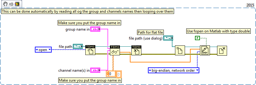
Writing data to extend the acquisition of data for the sampling rate high file
These are the tasks that I have to do to take noise measurements:
(1) take continuous data to USB 6281 Office, in a sample of 500 k (50 k samples at a time) rate.
(2) save data continuously for 3 to 6 hours in any file (any format is OK but I need to save in a series of files rather than the single file). I want to start writing again file after every 2 min.
I enclose my VI and pictures of my setup of the task. I can measure and write data to the file continuously for 15 minutes. After that, I see these errors:
(1) acquisition of equipment can't keep up with the software (something like that, also with a proposal to increase the size of the buffer...)
(2) memory is full.
Please help make my VI effective and correct. I suggest to remove him "write in the action file" loop of consumption because it takes a long time to open and close a file in a loop. You can suggest me to open the file outside the loop and write inside the loop. But I want to save my data in the new file, after every 2 min or some samples. If this can be done efficiently without using Scripture in the measurement file then please let me know.
Thank you in advance.
This example here is for a single file and a channel, you should be able to loop over that automatically. The background commentary should be the name of the channel, no group namede the name of the channel in the control.
Maybe you are looking for
-
MacBook Pro 13 "Retina Display Usb Port does not... !!
MacBook Pro 13 "Retina Display right usb port does not... I tried to plug in and out still it doesn't then I rebooted my macbook and again inserted the USB, it worked... !! Why this problem is caused? today is the 5th day since I bought my macbook...
-
How can I view my address book next to my e-mail page, if I want to forward a message
I also lost my address book on the left of my screen, and now I am unable to get it back.How he do back into place.Gordon
-
Multimedia audio controller driver for windows 7 on compaq presario r3000
Hello, I need your help again. I solved this problem with your help and saved the link in 2014. Window 10 guided to level and my computer slugger. Now, I have reinstalled windows 7 and have new need this audio controller. However, the link for this d
-
Windows Vista Readyboost Puzzle
Hello everyone. I have a bit of a puzzle on Windows Vista Readyboost. I have a windows 7 PC and a friend has vista. I tried readyboost using two USB keys, a 4 GB stick and half-full 8 GB stick vacuum. It seems that Windows 7, I am allowed to use more
-
Windows Update keeps providing a status update (KB2463332) that I glazed manually
I continued to get 65 B error code when you try to install Microsoft SQL Server 2005 Express Edition Service Pack 4 (KB2463332) with Windows Update , so I downloaded manually from Microsoft downloads. However no one told him Windows Update , so keep