adjustment of curve input gives the output
Hi everyone, I'm having a problem with the adjustment function
I take the output, what I give as input, where am I wrong?
example, I give 4 values, if I get 6 values that it works, but I need to do with 4 values.
any ideas?
Thank you
Tags: NI Software
Similar Questions
-
How to synchronize the analog input and the output of two different USB data acquisition boards
Hi all
I have two tips very different USB NI USB 6008 case, which I use to acquire the data (analog input) and a USB of NI 9263 is a output analog only site I use to route a signal (in this case a square pulse). The reason why I use the outputs analog 6008 is because I need to deliver negative tension and need the full +/-10 v range.
Looking at similar positions, I'm pretty sure that I can't use an external trigger or a common clock, I also tried to use the timed synchronization of the structures but no cigar.
I'm including a quick vi I whipped showing how the jitters because of the lack of synchronization signal. The OD of the 9263 connects to AI in the 6008 in this example.
I talked to a specialist in the phone and tols me that's not possible.

-
I have two sound cards. Can I use the input to the output to another?
Basiclly the problem I have is that I use one of my as a configuration of 5.1 sound cards speakers (I put the MIC and line as output) and I found another sound card in another PC. The question that I have, that now I'm not a line or a microphone available for the first sound card, is possible to distribute the Line In input of the other card, to the first?
Hi KiralyAlex,
Unfortunately, it is not possible to perform this task, because at some point that a single sound card can be defined as a default device.
However, you can use your favorite search engine & download any third-party software that could serve the purpose.
Note: Using third-party software, including hardware drivers can cause serious problems that may prevent your computer from starting properly. Microsoft cannot guarantee that problems resulting from the use of third-party software can be solved. Software using third party is at your own risk.
Hope the helps of information.
-
T410 audio port gives the output on one side of the enclosure
I had a T410 recently and have been pretty happy with it.
The problem is, my normal headset used to work initially, had no trouble getting sound in both left and right headset speakers. Then slowly I started to have trouble getting sound in my left ear piece. I had to twist and turn the connector and it would work occasionally and it does not work most of the time.
I tested with two headphones that work with other devices, but when I connect it with this, I hear in my right atrium only. Speakers work fine.
How can I solve this problem?
Hi and welcome to the forum!
I have 3 iPod headphones, 2 of them are compatible parts but the 3rd is authentic Apple. Headphones compatible when connected to my T400 with the same problem you are describing, the sound comes only from one of their ear pieces and me too I have to twist and turn in a certain position for its exit from both ends. However, the genuine Apple earphone works out of the box, but all these 3 headphones work fine with my iPod. My conclusion is that only connect headphones of good quality with the thinkpad.
But the problem could be different, I suggest you look at this thread and Knowledge Base article, maybe what you need is just an adapter to resolve this problem: -.
http://forums.Lenovo.com/T5/T400-T500-and-newer-T-series/T510-combo-mic-audio-port-usage/m-p/217613
I hope this helps.
-
Redirect the output of the JVM in WLS
Hello
Can someone please give me some input on the output redirection FMV to the Weblogic Server log. I wanted to just understand what exactly happens if we allow redirect JVM output?
1. it keeps the two log .out & .log files and also write JVM on Weblogic journal as well?
2. it will keep one log (.log) and output all Weblogic & JVM will be recorded in this single Weblogic journal?
Thank you
Sicard.
Hello
We actually use this flag in our environment, and the .out newspapers are always generated. What happens is, exit JVM is redirected to the .log file, with journal entries that appears as a message of severity of the NOTICE.
I think you did already, but in case you don't have it, you can see this document for more information > http://docs.oracle.com/cd/E12839_01/web.1111/e13739/config_logs.htm#WLLOG163
(Although the document does not specify if the .out files could still be generated or not)
Kind regards
White
-
Is it possible to its right input at the exit route?
I connected my PS3 to my monitor, but because I'm using a HDMI-DVI adapter I can't use the HDMI for audio.
Is it possible to use the optical sound on my pc as the input and the output in real time through my pc speakers?
Hi Matt_bowey,
It is not possible. However, you can use a sound card that supports this option. If this is no good, then you can also use an external switch that will act as a separator.
Diana
Microsoft Answers Support Engineer
Visit our Microsoft answers feedback Forum and let us know what you think.
If this post can help solve your problem, please click the 'Mark as answer' or 'Useful' at the top of this message. Marking a post as answer, or relatively useful, you help others find the answer more quickly. -
R12 - report language different from the output
Hello
We have drafted the report in English and when we copy and run in R12 it gives the output in a different language as the Russia.
I checked the Etcc settings... all the shows with English.
But when copy us the contents of the report (pdf) in Notepad, that it converts into English.
Pouvez one facing this type of questions, suggestions?
Thanks in advance.What happens if you download the concurrent demand for output file from the server (under $ $APPLOUT APPLCSF/directory) to your customer and open, does show English or something else?
Thank you
Hussein -
I am an absolute beginner to Labview, and I have so many problems that I don't know if I'll be able to finish it, even if it seems that it should be so simple.
Here is the complete program, that I need to create, and then I'll ask my question and I hope I can get help on what is possible on this forum.
I need to have an oscilloscope and a generator of signals communicate. I need to start a frequency and the power of the signal generator. The oscilloscope read this power as a tension (I've got this part so far). Then I need to compare this voltage to an assigned value and if they are different, adjust power accordingly on the signal generator until the voltage is equal to (with a tolerance) and the value of the rated voltage. Once this is done, I need to read the power of the signal generator and then move to the next frequency.
The hardest part for me so far and the question for this forum is: how to compare a value of output with a value assigned and so different, adjust the output value until they become equal, remembering that I'm adjusting a power on the signal generator to get equal tension on an oscilloscope?
I hope this question makes sense. So I'm back to this program and I don't have anyone in my group who can help me, so I'm desperate. Thanks in advance.
davedude,
The short answer is to use the range of comparison functions. To make a comparison with a tolerance, you can use the cooker and force function. Always keep the Help window open context while you program - it explain the inputs and outputs and describe the basic function of the node that the cursor. One of the outputs is a Boolean value called in range? That wire to the terminal of selector of a box structure. In the case of 'out of Range', carry out the adjustment.
The entire program should be in a while loop if all continues to repeat until done or until a button is pressed.
A good approach for this kind of problem is to use a state machine, which can be implemented as a while loop that contains a structure of housing. There are examples that come with LabVIEW.
Lynn
-
adjustment of curve with the equation
I have a program in which I receive a response signal which is of the form A * cos (w * t) * exp(-t/T2), where A is the amplitude, w is frequency, t is time, and T2 is the spin relaxation time. Is it possible to adjust a curve in this graph and output the values of the variables? I have tried many options in labview but can't seem to find a way to add the variable T2.
Thank you
Justin
LV8.6
-
Input from and output to the drummer
I have an all-in-one desktop PC, and I know that there is only a single port, 3.5 mm jack to connect headphones with microphone, which is generally used for the players to discuss with the other members of the team in some games online.
So we have this mixer table 32 channels sound system, with separate input and output ports. I rigged with success a cable to connect the output port of the mixer to the port of Desktop 3.5 mm jack, so I can listen to music on a multimedia player and drummer distribute some trendy top speakers.
But I can't understand how I can record the audio output of the console on the desktop computer. I mean, when there is someone who makes speeches with a wireless microphone that connected to the mixer, I do not know how to save it. I tried to connect the output of the mixer to Desktop 3.5 mm jack, but he recorded only static. sometimes just the silence.
1. is there a way I can connect the TWO console input and output to the 3.5 mm jack plug mixer?
2. If can't, which cable / jack is required to perform records (connecting the output of the mixer with the 3.5 mm jack plug)?
Help, please.
I'm a nerd. A super nerd.Hello
The following piece of cable/wire can help:

Kind regards.
-
Switch the output of a workflow parameter to another workflow as input parameter?
Hi all
I have created a list of resources and want to add a virtual machine in this resource pool. There are two workflow, 1. Pool of resources & 2 creation. Cloning a VM. I'm creating a different workflow and by adding this two workflow. I don't know how to pass the value of the output parameter of the first stream of work performed as input to another workflow running. Can anyone help? Can anyone attach the workflow example?
Thanks in advance.
Hello
You must create workflow attributes (in the "General tab" of your workflow) and link out of the first workflow settings that you call to them. You can then link the same attributes as parameters to the second.
Watch this video (and all others in the www.vmwarelearning.com/orchestratorseries) for an explanation: http://vmwarelearning.com/2nB/understanding-variables-and-variable-binding-overview/
See you soon,.
Joerg
-
Adding points to the adjustment layer curves in PsCS6 broken?
In CS3, CS4, and CS5, I was able to:
b add a point (corresponding to the position of the eyedropper on the image) by Ctrl + click RGB composite curve; and
b add a point (while wearing on the RGB composite curve) to each of the curves by Ctrl + Shift + click on channel red, green and blue.
No approach seems to work in my CS6 (PsCs6 x 64 last updated, in Win 7 x 64).
Is a kind soul able to tell me the correct key combination to achieve the desired result, or is there really a problem with CS6?
Post edited by: hienromaric
It should be documented here:
https://helpx.Adobe.com/Photoshop/using/curves-adjustment.html
Most of the above is the on image setting target adjustment (tool) must be enabled
(the hand symbol with arrows in the properties panel)
then you click on the image (no modifier key) to add a point to the composite line and Ctrl + Shift to add points to the red, green and blue channels.

-
How to use the Bpel output as input to the stored procedure
I am a beginner SOA. The scenario is to use the output of a BPEL process in a procedure stored as input and validate it against the data in the database. The data received from the BPEL are compared with fields from different tables.
It's basically a business process data validation.
The output of BPEL is an Xml file and how it can b used in the query of a procedure?
Published by: 869091 on June 29, 2011 12:14 AMThe output of the BPEL process is in XML format.
Your requirement is not clear, please state it correctly what you doing.Yatan-
-
I connect to a generator of signals MXG (N5183) via the lan, Labview 2009 with the labview driver. I get the above error when trying to activate the output. Is this a bug in the driver? Everything else works fine.
-
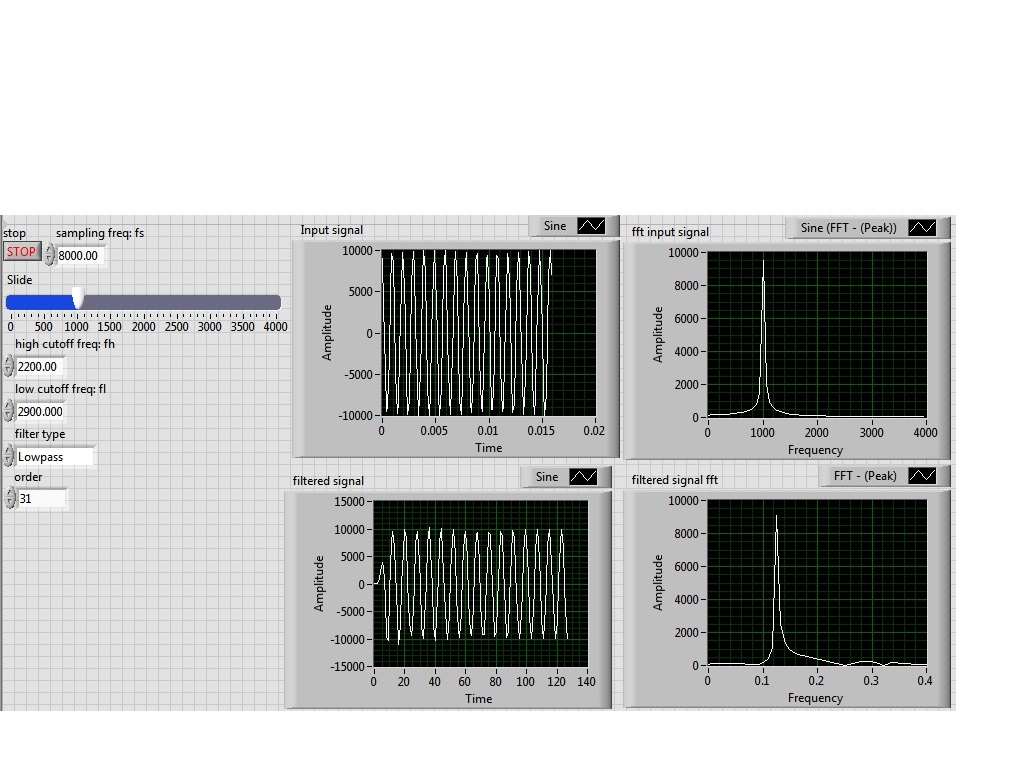
I'm simulating a sine wave at approximately 1000 Hz (I'm variable according to the frequency with a slider), I would like to pass this signal by a lowpass filter (butterworth) with a high frequency of 2200 Hz cuttoff and a low pass to 2900 Hz frequency. However, the output after the filter frequency seems to be lower in the order of a thousand. the output frequency is about 0.1 Hz.
Y at - it someone who can guide me please to solve this problem, I tried different filters and I'm still having this problem, it would be incorrect sampling?
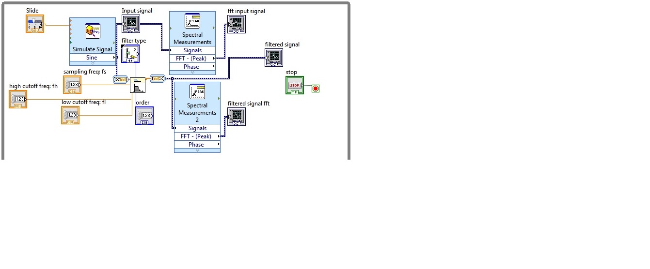
I enclose the block diagram and the front panel
Because you use express screws and the type of dynamic data...
You convert the signal of DDT (which contains the clock information) in a table DBL to perform filtering. Take it a DBL array (which contains no data of timing) and converted it into a DDT (which now contains no data timing). That's why when you try to view and analyze it you have lost all the data timing (frequency).
If you were to exit table DBL of your filter and build a wave form and provide the dt to the waveform of the sampling frequency control, then it will work.
Better yet, ditch the DDT and use waveforms from the beginning


Maybe you are looking for
-
I look after a small PC of old ladies in Australia, of the Canada. She used to watch live webcams to the Canada video looking at snow & ice but now with a new HP PC it can not display the stream live... or to be more precise that she can see, but th
-
Today, I changed my facebook password, I remember my old password but I forgot the neww 1 How do I just get my old password back with the new 1?
-
Reference Dell A10 946 does not
See the description in the "title area' above. My printer (Dell 946 A10) is not communicating with my command 'print '. I can copy, scan & Fax, but cannot print.
-
Change Desktop Gadget showing incorrect comaparisons to the US Dollar
Original title: Google Desktop Gadgets - incorrect currencies Change Desktop Gadget showing incorrect comaparisons to the US Dollar
-
Tungsten e2, replaced by one used, used to synchronize with PC
Help! I had a tungsten e2 for years, broke the screen now. Replaced by a used one on Ebay. You try to transfer old PC data (contacts, calendar, photos) when I plug in hotsync transfer old data from the old user to my PC. But not my data to the new u