After the acquisition of analytical data
Hello
We use the producer/consumer model to design a spirometer OR myDAQ.
And hae probblem on how to enter the analysis stage.
Measures
1. "start"-> 2. so that the data of loop aquire-> 3. Click on "Stop button"-> 4. show on graph xy cursors and the user.
5. the user could click "Start" button to start the next round.
How problem so he could run in step 3 to step 4 and keep the window still works.
I have attached our code here, DiagnosticRevB.vi is the main VI.
Thank you
Li Tonghua
Hello
The problem you are experiencing, it is that you have a race condition for your variable to "stop". You write to it both the producer and the consumer. When you press the stop button, it will place a stop command, and then set stop true. In your break in the producer State, you set stop to false.
The race condition occurs because you don't know in which order the variable stop will be set to true or false! Your shutdown state could be executed before labview stop sets to true, the stop State will define then stop to false, and then the structure case will mark the high true. This is actually what is happening, and the reason why your code isn't able to be restarted.
You need to fix this race condition to make your code robust and work properly. One way to do is to write only stop in the loop of producer (your loop with the structure of the event). Take a look at my enclosed solution.
Tags: NI Software
Similar Questions
-
I want to integrate the ANSI C sample program ReadDigPort - ExtClk.c in my own big package.
I want to use the internal clock of the BNC NI USB-6259 (.. 80 kHz 120 kHz).
In the document:
High speed M: Series Multifunction DAQ for USB - 16-bit, up to 1.25 MECH built-in BNC connectivity. / s,.
is written:
Or sample DI source clock: Any PFI, RTSI, HAVE sample or convert clock, AO, Ctr n out internal and many other signals sample clock
The digital subsystem doesn't have its own dedicated internal synchronization engine. Therefore, a sample clock must be provided another subsystem on the device or from an external source.How can I use internal clock case OR USB - 6259 BNC for the acquisition of digital data in my own big software?
With what other subsystem on the device can generate a source of the clock? How?It is possible to set a clock on an internal counter (for example ' Dev1/ctr0"):
Creates channels to generate digital impulses that define the freq and dutyCycle and adds the channel of the task that you specify with taskHandle.
DAQmxCreateCOPulseChanFreq (taskHandle, "Dev1/ctr0" units, clockName, idleState,
initialDelay, freq, the duty cycle); worksBut it is not possible to drive this internal clock to a terminal (for example "/ PFI0/Dev1"):
DAQmxErrChk (DAQmxCreateCOPulseChanFreq (taskHandle, "/ PFI0/Dev1", clockName, units, idleState, '))
initialDelay, freq, the duty cycle); does not work: error DAQmx: measurements: type I/O of the physical channel does not match the type of I/O required for the virtual channel you create. Name of the physical channel: PFI0. Name of the virtual channel: clockThe sample clock source can be derived from an external terminal (for example "/ PFI0/Dev1"):
Sets the source of the sample clock, the sample clock rate and the number of samples to acquire or generate.
DAQmxCfgSampClkTiming (taskHandle, "/ PFI0/Dev1", maximumExpectedSamplingRate, DAQmx_Val_Rising, ")
DAQmx_Val_ContSamps, bufferSize); works. Acquire or generate samples until you stop the taskBut it is not possible to derive the internal counter of the clock (for example ' Dev1/ctr0"):
DAQmxCfgSampClkTiming (taskHandle, "Dev1/ctr0", maximumExpectedSamplingRate, DAQmx_Val_Rising,
DAQmx_Val_ContSamps, bufferSize); does not work. Error: Acquire or generate samples until you stop the task: make sure that the name of the terminal is valid for the specified device. See Measurement & Automation explore valid names of terminals. Property: Property of DAQmx_SampClk_Src: DAQmx_SampClk_ActiveEdgeSource device: Terminal Source Dev1: Dev1/ctr0Hi datafriend,
using what it says is correct:
Or sample DI source clock: Any PFI, RTSI, HAVE sample or convert clock, AO, Ctr n out internal and many other signals sample clock
The digital subsystem doesn't have its own dedicated internal synchronization engine. Therefore, a sample clock must be provided another subsystem on the device or from an external source.This means that if you do not use an external signal as clock you can use the sample clock to HAVE it on board or at the output of the internal counter.
There are also 2 ANSI C examples in this regard:
http://zone.NI.com/DevZone/CDA/EPD/p/ID/4485
http://zone.NI.com/DevZone/CDA/EPD/p/ID/4488
So in both cases you have to use a fictitious task you need only for the generation of the internal clock (HAVE or CTR)
-
VMS, powering down after the loss of connectivity data store
My apologies for the newbie question.
I have 2 ESXi4 hosts connected to a SAN, iSCSI via a switch. I have server vSphere and HA but not DRS. The switch has rebooted unexpectedly, that caused a rupture between the hosts and the storage where the virtual machines. I expected the VMs system crashing, but it seems that they will switch off in an orderly fashion.
After the reboot of the switch, the virtual machines automatically power (as has been fixed in my vSphere client)
So was power off start function / stop into my vSphere client settings? I don't see anything in the newspapers about HA and I didn't think it was a function of HA.
Check the properties of VMware HA (in cluster settings).
You will see that the response of isolation is set to shutdown the virtual machine.
Isolation is when a host to see that he can not ping person.
If you restart the switch that all guests get in isolation mode.
You can change the timeout with HA advanced settings:
http://KB.VMware.com/kb/1006421
André
-
Update of the segments of waveform by Omega 3000 for the acquisition of personal data
Hi all

I'm having some trouble with segments of waveform of updationg through my acquisition of data personal omega 3000.
The goal is to generate a 1 Hz square wave, which updates of each cycle.
I wanted to avoid generating a new waveform of each cycle, I tried to update.
In the example given by omega, a waveform consisting of 5 segments is generated, and then the third segment (index 2) is updated.
I tried to rebuild so that a single segment is generated and then updated, but I failed miserably.
Configuration of the example VI in this way is not too.
In fact, I'm not even able to set the example VI to update other segments than the third.
I guess that 'Wavelet index' is the right point to set it, but if I put it to sth. other than 2 it just refreshes not anyting.
I can change the five segments of the curve and the update also, but I'm not able to update for nothing, but the second segement.
I hope it's just a simple value to change, but I can not find...
Does anyone have an idea what I might try?
Thank you very much in advance,
Keksbold
PS: I have attached a file so you can see what is the problem:
5 segments: sine, square, triangle, tooth of saw and noise, and for some reason I'm not able to update everything, but the third segment...
Problem solved!
I don't know why, but removing the status of wave DAQIO VI sub set.
I'd be really interested to know why the VI behaves like that anyway, so if anyone has an idea...
(But is more vital
)Thank you all!
Keksbold
-
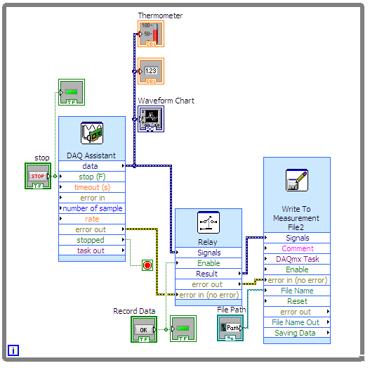
Hello I'm trying to read in a temperature of a thermocouple and displayed on a waveform graph and at the same time, I want to write data to a file at a significantly lower frequency. Currently, I am sampling data acquisition at chaque.01s and I would like a sample to write to the file every 2 s. I thought of activating/deactivating the option activate the relay every 2 s, but I don't know how to do that and I wouldn't be surprised if there is a standard way to do this, but I've not been able to find.
Thank you
Miguel
If you are sampling of chaque.01s and you want to write a snack every 2 s, what about all the other samples? You want to just throw away? You read so 200 samples in 2 seconds. But you want to write a sample. You can do it if you don't mind losing the other 199 samples.
You could use the elapsed timer function and the release of the elapsed time of a structure of business wire. Put your writing inside the real deal function. Nothing in the case of false. Make sure that all of the timer to reset automatically. If every two seconds, the case will be set to true, and will be called the write function.
-
I'm under LabView 8.2 on Windows XP, with an NI PCI-MIO-16XE-50 card. I tried to install DAQmx 9.1.1 on my system, but libraries DAQ do they not appear in the folder C:\Program NIUninstaller Instruments\LabVIEW 8.2\vi.lib.
Here is the chronology of the events:
After you add the DAQ card to my computer, I installed DAQmx 9.4. When I learned that 9.4 DAQmx is incompatible with LabView 8.2, I uninstalled and replaced with DAQmx 9.1.1 and installed the patch.
I can see my device in MAX, but DAQ Assistant is not listed under functions > Express > entry in LabView.
From advice on forums, I tried using Add/Remove programs to change NI DAQmx 9.1.1. Under 'Application Development Support' I see "Support of LabView 8.2" has a green check mark, but the text in the right panel says "this feature will not be installed. A newer version of this product is already installed on your computer. »
I tried to "Repair" NI DAQmx 9.1.1 (and patch), but did not see a difference.
I guess I need to uninstall the latest version of "Support of LabVIEW 8.2" before installing OR-DAQ 9.1.1, but there is no element of that name in Add/Remove Programs > National Instruments software. How uninstall this version of LabView Support for DAQmx 9.1.1 will install correctly?
Or, if this is not the source of my problem, what is?
Thank you!
-
Data do not form filled - using Fetch manual process (after the header)
Hello
I have a FORM based on the EMP table... say with the next field.
1. non - employee P1_EMP_NO
2. employee name - P1_NAME
3 employee location - P1_LOCATION
I have another table called EMP_STG, it's the temporary table for EMP.
I have suite 2 button on the page of the form.
-Save (when I click on it, the data are inserted into the EMP table)
-Save temporary (when I click on it, the data is inserted into the temporary table EMP_STG table)
The form is already have a Fetch automated line process (after the header) to extract data from the EMP table. It works very well.
I created a second process of recovering data from the temporary table EMP_STG.
Extraction of EMP_STG / after the row header
The problem here is P1_EMP_NO & P1_LOCATION are not getting filled. Process works fine, no error...
Only form elements are not get filled.
Note:-both the above automatic Fetch & Manuel Fetch based on some condition and a moment alone executed.declare cursor c1 is select * from emp_stg where emp_no = :P1_EMP_NO; begin for c1_rec in c1 loop :P1_NAME := c1_rec.NAME; :P1_LOCATION := c1_rec.LOCATION; end loop; end;
Thank you
DeepakI guess that you will then have to consider the options, what I said in a previous post.
CITY
-
complete the loop and get data
I need to acquire the acquisition values of data every x seconds. Waiting in the loop of data acquisition is defined so that the next N samples are acquired after x seconds. Pressing stop the loop of consumer DAQ stops after the sec x which is connected to the wait function.
1. how to stop the inner loop immediately when you press a stop?
I also write acquired samples after doing some calculations on the samples.
1. plan of sample of the queue to file consumer loop. Is there any other recommendations such as drop loop is not without samples? How many data can an expectation of the queue?
Thank you.
sonotk,
You've missed the point. Rather than having a 5000 milliseconds of wait, use an expectation of 100 ms and count the number of times that you have been waiting for 100 ms. When the count reaches 50, sample and start the count again.
The counter is just in the shift register containing an integer. Inside the while loop you have a box structure. Test the shift count register to see if it is 50. If set to True, use the real case of the structure of the case. Inside, it's all in your loop except waiting and the logic of the judgment. In the case of false, you add 1 to the shift register and wait 100 ms.
Looking at your picture code once again, it seems that the shift with TempData and VoltData regsiters are not necessary because you never use the data previous iteration on the left side.
Ranjeet,
Make a simple VI with two loops and some expectations. Run with execution highlighting market to see what is happening. It is a good learning tool.
Lynn
-
We send 5v data acquisition using a voltage generator. Hook us it up to a voltmeter and see 5V. When connect us the generator voltage to a valve "normally open" parker, the voltmeter indicates .14V. It seems that when we connect the two sons of the valve for the voltage generator, the son act as pattern. We want to control the voltage flowing to tap through Labview. We checked the wires to the valve and they work very well, because if we send a constant 5V since the acquisition of data and put ashore, she, the voltmeter indicates 5V. Someone knows why the son act as pattern and low blood to .14V?
nsatpute wrote:
Our data acquisition is NI USB-6259. The valve requires only a 5V max and our DAQ provides up to 5V. However, after connecting the valve to the acquisition of data, the grave tension to almost 0. We start from the principle that the son somehow act as the reason, but we are not sure if this is the case.
The question here is not how much voltage the valve wants, it's the current needs of the valve. The 6259 can put only 5mA via an analog output. Your very likely tap needs much more than that. If you need to add in an amplifier circuit that can supply more current to operate your faucet.
-
HAVE fast acquisition after the signal from trigger-DI
Hello world
the work of the VI I train is basically very simple:
There are 8 analog inputs, which need to be given reading a entry digital-trigger after.
Parameters: frequency of sampling per channel: 2 ms/s, number of samples per channel: 1024
This acquisition is very often repeated (1000 x +). So I put the trigger and the part of reading inside a while loop. The task initialization happens before this loop and the task is closed later.
The problem that I have is the speed! The acquisition itself (1024 samples/channel to 2 ms/s/channel) should (in theory) be done in the ~0.5ms but actually lasts longer...
My goal is to make the process: trigger-> acquisition in 2ms. He is currently, reliable with a rate of repetition of 15ms. ~
Do you know the guy in any way to increase the speed? I played a bit with manually set size of buffer and initialize a task dedicated for the trigger itself. The two does not improve it.
Hardware DAQ-I'm by train is USB6366 and a system of SMU with a PXIe6368 inside.
I don't really know where this quite simple line, time is lost...
Best regards and thanks,
Michael
Hello mschoeff,
If I understand you correct you want to retrigger the acquisition. Then you must
Configure the trigger outside all loop and use the node property to enable the trigger.
Here is an explanation:
Support for redeclenchables tasks on X Series multifunction data acquisition cards
It may be useful
-
Real-time display at the high frequency of data acquisition with continuous recording
Hi all
I encountered a problem and you need help.
I collect tensions and corresponding currents via a card PCI-6221. While acquiriing data, I would like to see the values on a XY graph, so that I can also check current vs only voltage/current / time. In addition, data should be recorded on the acquisition.
First, I create hannels to analog input with the Virutal DAQmx channel create, then I set the sampling frequency and the mode and begin the tasks. The DAQmx.Read is placed in a while loop. Because of the high noise to signal, I want to average for example every 200 points of the current and acquired for this draw versus the average acquisition time or average voltage. The recording of the data should also appear in the while loop.
The first thing, I thought, was to run in continuous Mode data acquisition and utilization for example 10 k s/s sampling frequency. The DAQmx.Read is set to 1 D Wfm N Chan N Samp (there are 4 channels in total) and the number of samples per channel for example is 1000 to avoid the errors/subscribe for more of the buffer. Each of these packages of 1000 samples should be separatet (I use Index Array at the moment). After gaining separate waveforms out of table 1 d of waveforms, I extracted the value of Y to get items of waveform. The error that results must then be treated to get average values.
But how to get these averages without delaying my code?
My idea/concern is this: I've read 1000 samples after about 0.1 s. These then are divded into single waveforms, time information are subtracted, a sort of loop to sprawl is used (I don't know how this exactly), the data are transferred to a XY Chart and saved to a .dat file. After all that's happened (I hope I understood correctly the flow of data within a while loop), the code in the while loop again then 1000 samples read and are processed.
But if the treatment was too long the DAQmx.Read runs too late and cycle to cycle, reading buffer behind the generation of data on the card PCI-6221.
This concern is reasonable? And how can I get around this? Does anyone know a way to average and save the data?
I mean, the first thing that I would consider increasing the number of samples per channel, but this also increases the duration of the data processing.
The other question is on the calendar. If I understand correctly, the timestamp is generated once when the task starts (with the DAQmxStartTask) and the time difference betweeen the datapoints is then computed by 1 divded by the sampling frequency. However, if the treatment takes considerable time, how can I make sure, that this error does not accumulate?
I'm sorry for the long plain text!
You can find my attached example-vi(only to show roughly what I was thinking, I know there are two averaging-functions and the rate are not correctly set now).
Best wishes and thank you in advance,
MR. KSE
PS: I should add: imagine the acquisition of data running on a really old and slow PC, for example a Pentium III.
PPS: I do not know why, but I can't reach my vi...
-
Hello
I am currently working on the acquisition of data from a unit of 2 balls of hair, installed with a Zilla controller on an electric vehicle. Hairballs allows other devices to the device through a serial port. The option of data acquisition for displays information like speed, tension etc.
I use Teraterm, a terminal Communicator to start communication with the device of hairballs. After having sailed in the various menus, I can access the DAQ feature that provides data continuously to the status of the various components of the vehicle. I saved the logfile of teraterm (Teraterm - Results.txt). 5B 01 0b C8 03 53 02 39 27 OMFS is, for example, a sample of data from the module of data acquisition.
When the port is configured to send these data, I close the program Teraterm and run the LabVIEW VI (read and Write.vi series). It accepts 2-3 rows of data (error LabVIEW - 2.jpg In Motion) and then stops. I know there is a message of error involved, but I think that its storage in what concerns the information in the file (this is another problem, I need to resolve, the file is always empty).
Could someone help me with this problem please. Why the software ends the execution after only 2-3 loops. Sometimes he starts to accept data from the middle (@ 1 0b C8 03 53 02 39 27 OMFS for example) and stops after displaying the it.
If there is information required please let me know.
Thanks in advance.
The error you get is:
1073807252 VI_ERROR_ASRL_OVERRUN A time-out error occurred during the transfer. A character not read in the material before the arrival of the next character. Your buffer is probably full of data.
-
Hello
I use the card PCI-6111.
I am trying to acquire analog data on channels dev1/ai0 ai1/dev1 using pulses of external clock connected to the PFI0 channel. I also want to trigger the acquisition, when the channel dev1/ai1 signal reaches certain level. I send a triangle wave channel dev1/ai1, and I need the data only for the front.
I have configured the task in the following ways:


However, I get the error-89137 after function DAQmx Start Task:
Specified route can not be satisfied, because it requires resources that are currently in use by another route.
Source device: Dev1
Terminal of source: PFI0InputLockOut
Target unit: Dev1
Destination terminal: AnalogComparisonEventResources in use by
Task name: _unnamedTask
Source device: Dev1
Terminal of source: PFI0
Target unit: Dev1
Destination terminal: AI/SampleClockTask name: _unnamedTask
If I change the internal clock external clock - switch works. If I pull the trigger, the external clock works, too. But these two tasks do not work together.
Help? Advice? Thank you!
-
Use of data cell after the upgrade to iOS 10.0.2 has increased dramatically
Hello:
I noticed a HUGE increase in mobile data usage by my phone (iPhone 6s) after the iOS to 10.0.2 update. I had not changed anything since before the update. A few days after my phone iOS update my more than double to 15 days prior to the cell data update! I went under a GB to 2.2 GB for two days. I am only allowed 2.5 GB of my company. Assist of WiFi was interrupted. I am connected to a wifi most of the time, all day at the office and at home in the morning and in the evening. I haven't changed my phone usage habits nor have I down loaded new applications. I also did all the stuff reset once I downloaded the update as turning on and off, hold down home and appears on the sides until that little Apple.
I looked in the cell parameters section and noticed a few things that consume more data:
Facebook: I had disabled cell Facebook use. However, there was a large amount of data used. I also, by habit, only check Facebook when I'm at a known wifi spot as the House or the office. It was less than a MB before and near a GB of data in 2 days.
YouTube: Idem, had turned off cell phones and only look at the House.
Maps - never used but the use of data.
e-mail-HUGE amount of data used. Normal use for me. in the past, the amount of data has been a MB. Now it's 65 MG in 2 days,
Siri - I do not use Siri as in "Hey Siri" or by using voice commands. I use it from time to time to the voice on texts.
AccuWeather. Even.
It's just as much as the apps that I use, the rest is electronic mail and stuff systems. I uninstalled nearly all applications except for the few that I need as my ticket train and planning aps and mail want to stop this. I won't send any imessages anymore.
Quite an experience of something like that?
Yes! I have iPhone 6 - after that the update almost all my data is gone for the month! I do not have Wifi Assist on and I only use data when I'm home and can connect to Wifi!
I see my iPhone to connect to my Wifi then bounce to the cellular network. I have no problem with my home wifi network. This problem also occurs in the work. In addition, the network at work requires the password to the network - I type in iPhone tells me it's the wrong password, and then it connects. Then it disconnects after 2 minutes.
I tried to reset the Wifi feature. Help!
-
Buy unlocked iPhone 7 right after the release date
Friends good day! Let's say I want to buy an iPhone 7 right after the release date before apple officially begins selling the devices free SIM card. I'd be able to come simply to store and buy, for example, an AT & T phone to use with my operator? Because I know that they would be not selling sim free phones in the first two weeks. Or do I have to buy a plan as well and become a customer of AT & T? In other words, I need now a unlocked device, and can I get one without waiting for the start of the free features of SIM card sale. Thank you!
If you buy any iPhone outright directly from Apple full paying, it is carrier unlocked.
Maybe you are looking for
-
Hello I tried everything, I can use my Apple pay by buying a jewels in the shock of the clans, the thought and he does not. is it possible that I can buy gems using the pay for Apple.
-
How can I get my volume works again, ive lost somehow
How can I get my volume works again, ive lost somehow
-
I submitted my port of ScummVM for the PlayBook (and was about to start making a BB10 version), but the application was rejected with a rather ridiculous explanaition: "We cannot not authorized users can use pirate game files to play on this emulator
-
Cannot find the driver for cd/dvd
I have a HP Pavilion dv8135nr and my driver for cd/dvd drive does not work says that my driver is corrupted. I already uninstalled and reinstalled. I use the disc that came with my computer laptop but guess what does not work my cd/dvd drive. Any hel
-
No sound in the built-in speaker for laptop
The built-in speaker stopped working after I did the helmet, then the external USB speakers default devices. Even after the default internal speaker, it does not work. In addition, in Skype, we do not hear the other party if they can hear us. The sou