Algorithm of PID in 'PID and Fuzzy Logic Toolkit' and 'real time Module ".
Hi all
I am recently using LabVIEW 2011 and 2011 real time Module. My application requires the PID control.
Now, I have a problem. In the manual for "And Fuzzy Logic Toolkit PID", Chapter 2 "algorithm PID" it indicates non-interactive algorithm (also called the ideal algorithm, Standard or ISA) be used in all the screws of PID in the Toolbox. It seems that Yes from source code. However, in Chapter 3, "Using the PID software" arrays of calculation of PID parameters based on method of Ziegler-Nichols, which was developed for the interactive algorithm (also called the series, the real classic algorithm). D action has been included in the scheme of control, the settings may be different for the two algorithms. In fact, Cohen Coons and adjustment PID Lambda rules can be used for the algorithm used by the box tool with no conversion.
In addition, there is a PID function block comes with the real time Module, and I know not what PID algorithm it uses. Can someone help me?
Thank you in advance.
Su
In the "and Fuzzy Logic PID Toolkit, we use the University structure to implement all algorithms. Tuning techniques we show on the manual to express the original work and we try to keep the same as you would look at the literature. However, in our implementation of autotuning internally converted to the structure used by our algorithms to keep compatibility with our own implementation.
If you use an external source, you can use the Conversion.vi of Structure PID to change University, parallel or series of parameters in one used by our algorithm.
The PID included with the real time module is a 'copy' of our algorithm, and they have the same settings and behavior. The only advantage to use this function block, you have access to the parameters through variables.
Hope this helps...
Tags: NI Software
Similar Questions
-
PID and Fuzzy Logic Toolkit for students
As the thread title suggests. I am a student currently running on the student of labview version. I have a project, toolkit that I work it would greatly be benifitted by PID and Fuzzy Logic Toolkit. Is it possible for the students to get it without the price tag of $1000?
I talk to your school and see if they have any sort of academic discount program in place. If not, you can contact your academic field sales engineer local, which you can find here.
-
difference between the real time module and module fpga
Hi experts,
I was wondering if someone could tell me the difference between the FPGA and the module in real time (in short).
My understanding is that the FPGA module facilitates code LV that can then be designed for the specific advice of RIO, I have used this a bit in the past.
The real time module, I'm a little more unsure about, all I know is that it allows the creation of a 'real time' i.e. deterministic environment.
My request is this: I wish I had several control loops running on two tables of RIO, with the host PC mainly used for recording data and user interface. I see that I have no need of RT on the host (Win XP should be good).
Do I need the RT module?
You are right. In the scenario you describe, you won't need to LabVIEW RT. LabVIEW RT is used to create a deterministic execution on specific targets for intel such as the PXI-8106 and PXI-8108. You can still use strings and floating point on RT.
-
The problem that I have are Measurement & Automation Reconoce mi cFP-2200 pero no lo reconoce mi project osea that al tratar add a new target and the device don't lo encuentra en red y me da el error Bank does not
That tal Estel3an;
You can have several reasons para you no one el proyecto the CFP in red, the first seria as the IP address of you PSC not accessible from the sea, are sea porque esta in una diferente subred o porque haya complicaciones in red you see Québec no you allow verlo. En that mencionas como MAX if lo puedes music y detectar none are not likely tan, ordered checar the direccion pero of you PSC y determining what is in the same segment that you PC o see if no is "cae" you red momentaneamente y esto no you eprmita see the CFP.
Otra razon could ser as the instalacion del software to haya hecho en UN orden distinto al recomendado, for example if instalaste primero LabVIEW Real-time y despues LabVIEW o If instalaste los drivers (NOR-Fieldpoint) LabVIEW time before real tambien you could estar afectando. Instalacion practice are LabVIEW, despues Modulos (in this case LabVIEW Real-time) y por ultimo controllers (in this case NOR-Fieldpoint) of all manera las ligas queden creadas.
Por ultimo could deberse problem of material of the United Nations, el as ¿podrias asegurarte status LED parpadeando en este no you driver of PCP? para descartar than sea por a problema en el PCP is not in you PC.
I hope the information you sea ayuda.
Suerte
-
LabVIEW 2014 SP1, hardware and real-time PXI
I'm doing my third LabVIEW Wipe/reinstall in as many days, completely frustrated (and after several calls an hour with the support of NEITHER). Here's the situation:
I wrote a fairly large (1000 VI) project of Acquisition/control of our graduate students data used for behavioral experiment on sound localization. It was developed in 2012 LabVIEW with the module running on a PC/PXI system real time. It worked very well and was brought successfully under LabVIEW 2014 (with upgrades comparable to the software of the PXI.
About 18 months ago the students began to write their theses, and at one point stopped gathering data. Also, at some point, I upgraded the software on this system to LabVIEW 2014 SP1, but I am not sure that I never tested my software with this new system.
This week, I pulled up the system to use MAX to open some test on the PXI multifunction and DIO card panels to control manually one of the stimuli. I discovered that MAX could not communicate with the advice on the PXI system - he attributes them as devices VISA, indicating each Board with an icon with a red X means that he could not communicate with the IP that I had assigned to PXI. Yet, MAX (a) could "discover" this PXI, (b) MAX can 'see' its IP address, and (c) Windows could not only Ping the IP, but could FTP on the drive of the PXI and I could move files back and forth.
I did two sequences complete "Wipe/reinstall" using LabVIEW 2014 SP1, all giving the same result. I know it has worked in the past, including when I installed LabVIEW 2014 (without SP1), something I repeat myself now with my third installation. I discussed with OR (thin?) possibility that there is a "hidden defect" in the Distribution of the SP1, one that is visible to LabVIEW RT users using PXI hardware and go unnoticed because (a) install a few sites of LabVIEW versions SP1, (b) a minority use the RT Modules and (c) PXI is "old material".
If anyone has such a system or saw a similar problem, please answer. I'll do a follow-up post if I managed to 'fix' my system by this last reinstallation "a solution of worked before."
Bob Schor
Well, the answer is that, in my system, LabVIEW 2014 SP1 with LabVIEW Real-time connected to a PXI system does not appear to connect to boards plugged into the chassis. Returning to LabVIEW 2014 (fall release), installed in exactly in the same way that the three failed attempts of LabVIEW 2014 SP1, works immediately. Engineers OR will try to duplicate/verify/possibly patch? in this issue.
Bob Schor
-
Continuous data acquisition and real-time analysis
Hi all
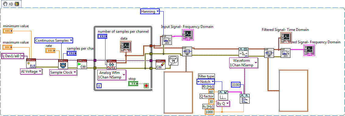
It is a VI for the continuous acquisition of an ECG signal. As far as I understand that the analog read DAQmx VI must be placed inside a while loop so it can acquire the data permanently, I need perform filtering and analysis of the wave in real time. How I implemented the block schema means that data stays int the while loop, and AFAIK the data will be transferred on through the tunnels of data once the loop ends the execution, it clearly isn't real-time data processing.
The only way I can think to fixing this problem is by placing another loop that covers the screw scene filtering and using some sort of registeing shift to transmit the data in the second while loop. My question is whether or not it would introduce some sort of delay, and weather or not it would be supposed to be the treatment in real time. Wouldn't be better to place all the screws (aquicition and filtering) inside a while loop? or it is a bad programming practice. Other features I need to do is back up the data I na file, but only when the user wants to do.
Any advice would be appreciated.
You have two options:
- A. as you said, you can place the code inside your current while loop to perform the treatment. If you're smart, you won't need to put one another while loop inside your existing (nested loops). But it totally depends on the type of treatment that you do.
- B. create a second parallel loop to perform the treatment. This would be separate processes to ensure that the treatment is not obstacle to your purchase. For more information, see here .
Your choice really depends on the transformation that you plan to perform. If it's much the processor, this could introduce delays as you said.
I would recommend that you start at any place in the first loop and see if your DAQ buffer overruns (you can monitor the rear of the buffer during operation). If so, you should decouple the process in separate loops.
In what concerns or not ' it would be considered as real time processing ' is a trick question. Most of the people on these forums say that your system is NEVER in real time because you're using a desktop PC to perform processing (note: I guess it's the code that runs on a laptop or desktop?). It is not a deterministic systemand your data is already "old" by the time wherever he leaves your DAQ buffer. But the answer to your question really depends on how you define "real time processing". Many lay it will set as the treatment of 'live' data... but what is "actual data"?
-
Frequently corruption file characterset OCR and real-time CVS1454 exe file
HI I am facing strenge same problem in the application of vision. I'm using equipment NI CVS 1454. Is there an OCR on CVS application that inspect the product on the conveyor. I made different characters to choose file of different labels on the product. Now main problem is sometimes not exactly when my chracterset file, Pattern matching templete and corrupts my exe in real-time. I joined a few ok and corrupted file characterset here and also an exe in real-time.
When I open my file (.abc) characterset in Notepad, that I found damaged files after entering text.
####
#Date: Wed, Aug 1, 2008 11:28
#OSName: PharLap
#OSVers: 13.0
#AppName: PH_EXEC
#Version: 8.5
#AppKind: AppLibLVRT. DLL loads the address: 0x002F6000
I don't understand how this error massage journal if written in .abc or rtexe files, which make it currupt... I have also attached my structuring code image file.
Dear prashantpatel21,
I do not know how to disable the log of LabVIEW RT errors, at least, is not that you or I could have access.
It's the idea that deactivation of LabVIEW RT logging of errors will decrease even more the impact of corruption?
Have you made progress with your service request?
~ Nate
-
LabVIEW FPGA and real-time communication module
Hi all
I created a small program in labview FPGA which gets continually distance from the HC - SR04 ultrasonic sensor. The rest of the robot program is written in the time module real Labview. Is it possible that the distance calculated by FPGA module to read in time real module.
I used the FPGA just because there micro-deuxieme counter, which helps me get the distance from the ultrasonic sensor.
Thanks in advance.
There are many ways this can be done, according to your needs.
See the help article transfer of data between the FPGA and host (Module FPGA) for a breakdown of each method.
-
Over acquisition and real-time mapping
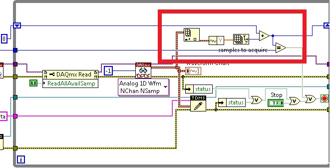
I think you should set a stop condition on your loop. After getting your last sample, you can call DAQmx Read again and you should get error-200278. That actually makes sense. You can index in your waveform and "Get the components of waveform" allows to get the table to, and then use an array size VI to account for the number of samples # you acquired (see photo). When you reach the number you wait, stop your loop. You can also solve this problem by reading the 10 instead of-1 and count (i + 1) * 10 = acquired samples.
Whatever it is.
Let me know what you find.
Germano-
-
Basic mx data acquisition and real-time application
Hello
I am generating an output through OR pxi 6733 using the basis of programming in labview 8.6 mx DAQ.
The problem is when I create a digital output channel indicating an error and say not supported for this target.
I'm not able to use the base that I have all of the same software version installed in the HOST and TARGET of mx daq.
I use in time real 8.6 and daq mx 8.9.5.
Thanks in advance.
You use DAQmx or DAQmx Base?
I guess his DAQmx because DAQmx Base does not run on the objectives of the RT.
Can you provide us with an error code?
Christian
-
installation and real-time help
-
Hi guys -.
Basically, I need to simulate a cRIO device without yet having equipment on-site, like this:
How to simulate the FPGA hardware target using with LabVIEW Project Explorer
Instead, I only get the options presented in the attachment "Add Target Options.jpg. I guess it's because of missing drivers, which I assume is due to an error that I made during a recent new LV installation installation went like this: I downloaded (not diskettes) and installed the following (in this order, the latest versions all around):
(1) LabView development system
(2) real-time module
(3) FPGA module
(4) NEITHER-RIO (previous installation-by-installation)
(5) DAQmx
At the end of (1) and (2), I got the screen shown in the second attachment ("Drivers Installer Message.jpg"), but could not able to recognize the folder "device drivers OR" (I also downloaded), or one of its subfolders.
According to me, I'm missing an obvious option to load the necessary drivers after installation, but can't seem to find reference to it in the forums. Could someone give me a little help in the right direction?
Thanks a lot and have a nice day.
-
Hello
I'm new to labview and trying to develop a system of eye tracking using labview 8.6. He has the vision development module, and I was wondering if this was not enough for the treatment and real-time image acquisition or could I need other software tools.
Yes, to acquire images from a webcam, you need drivers imaq-dx.
Take a look at this link:
http://digital.NI.com/public.nsf/allkb/0564022DAFF513D2862579490057D42E
Best regards
K
-
What is the difference between the file httpd.pid and httpd.lock?
What is the difference between the file httpd.pid and httpd.lock?Salvation;
Apache httpd saves the id of the httpd process parent in the file logs/httpd. PID.
LockFile
Sets the path to the lock file used when Oracle HTTP Server is compiled with USE_FCNTL_SERIALIZED_ACCEPT or USE_FLOCK_SERIALIZED_ACCEPT. It is recommended that the default value be used. The main reason for changing it is if the logs directory is NFS mounted, since the lock file must be stored on a local disk.
"For example: LockFile /oracle/Apache/Apache/logs/httpd.lock.
Please see:
http://download.Oracle.com/docs/CD/B14099_19/Web.1012/b14007/fileloc.htm#sthref254Respect of
HELIOS -
I'm using labview for the fault diagnosis, where the entrance would be numerical values such as temperature or vibration and after defuzzification reading, I want the output to a particular type of fault example imbalance of the tree or fuel pump faulty.
Now the labview after defuzzification gives me a numeric value, how I use fuzzy logic labview control & simulation when the input is digital and outside is a qualitative anomaly, a undetermined?
Thank you
Aliraja,
You can use fuzzy logic tool to deal with the digital inputs and determine what should be set out. However, the production value will always be numeric. The key element that you seem to be interested would find whatever the numerical value represents. While I can't give you a precise way to configure this system in itself, something you might look to do would go on the tutorial of fuzzy logic listed in Chapter 9 of the
LabVIEW PID and user manual for the fuzzy logic Toolbox. This document can be found here:
LabVIEW PID and user manual for the fuzzy logic Toolbox
How fuzzy logic, basically, is that it defines an actionable items and system settings to determine how the entries on the output of a system. He did this to simply classify the entries in specific categories (which are numerically specified) and the output, then a different category, which is just another representation of a numerical range. Because the output is going to be digital, I would focus on which values represent different vulnerabilities on your application and then write in a LabVIEW logical basis to determine what is actually happening. Once the system is set up (best done through fuzzy System Designer), this shouldn't be too difficult. Implementation of the system will be the most difficult part and will depend on how you want to configure the inputs and outputs.
Please look over the attached tutorial, which should explain if all goes well in-depth how to effectively use the Toolbox.
Kind regards
Keith M.
Technical sales engineer
Maybe you are looking for
-
Suggestion - I love the lizard, what is real through Mozilla mail accounts?
I hate gmail, mail from apple through the cloud and on and so forth... I use a VPN with the TorBrowser... I think it would be very nice if created Mozilla email like Tormail or other protected e-mail services, yes out-lay set up can be expensive, but
-
Why can't save the same bookmarks in different places?
Why can't I save a bookmark for a site in several places? If I him have already stored, for example, in the bookmarks menu, and I then try to save an extra copy to the folder of bookmarks, copy it to the bookmarks menu will disappear. It's incredibly
-
Firmware of the device wireless Broadcom lost in an update of the BIOS
Hello, I update my BIOS netbook (Aspire One AOD250). Since the original factory version v1.23 for one, lastest v1.29. Everything went very well but the card wireless; It does not work. Operating system tells me: Broadcom BCM94312HMG. Firmware is miss
-
Mapping of locations of network with x 64 Vista Ultimate view, I can't map a network location
Hi Rob Lydan,. Appearently, there is a known issue with Vista 64-bit and WebDAV. It is not a work around I know except for the 32-bit version, I could be wrong on that. You can ask this question in the TechNet forum to see if someone can point you
-
How to get rid of the message 8024002d insert the Microsoft works 9.0.msi disc
I have an Inspiron 1564 with Windows 7 that he had loaded Microsoft when I bought it. I received an error 8024002D, who tells me to insert discmicrosoft works 9.0.msi I did fi this error I have not had no disk how can I get rid of him?