analog indicator
Hello
This is my first post, even though I read it for a couple of years and you are a really useful guy.
I did an acquisition system in labview using picoscope and what I want to do is to display the data that I get in a counter (like old voltmeters or a regular analog device with a needle).
The problem I have is because the values that I get are not stable (it can jump from 5 to 150, then 30, etc.), the needle continues to go up and down and is not so easy to read. Is there a way to make the counter style more "analog"?
Of course if I have values from 30 to 50, and a peak of 150, then I won't see it. I see rather a peak of 80-100 as it should be less accurate in the peak values (or better slower) but more stable in average values.
Is it possible to do such a thing?
Thank you
Hi alx.
in an analog world, the meter acts as a low pass filter. If you need program a similar filter for values displayed in your meter.
I suggest to use PtByPtMean because it provides a moving average which is actually a low-pass filter. Start with a length of 10 sample. Larger values make the slower needle...
Tags: NI Software
Similar Questions
-
Size of analog input to see the digital indicator cover
I read a channel of analog input with several samples, and I want the magnitude of which is playing to display on a digital indicator which is on my front. I know that it is not possible to wire just the data directly to a digital display of the signal due to the difference in the data type. Does anyone have an ideal on how I can get around that?
Dear Thuillot
You can use 'Extract only your Information' function found in the range of signal processing.
You can find more information on this feature here
Kind regards.
-
REGZA TV REMOTE 32WL66A - analog capacity
This TV has an analog capacity?
I read somewhere that it should be a button on the remote control to switch between digital and analog - but its not obvious to me and not indicated in the owner's manual.
Since this is a forum for laptops and notebook options only, I doubt someone could provide details about this TV but if its not mentioned in the manual then I guess this switch between digital and analog is not available.
-
Hello
I'm new to LabWindows, and now I have a question.
I would like to generate the same signal on two analog outputs (SCB-68). My Code is this:
/*********************************************/
DAQmx Configure Code
/*********************************************/
Channel 1
DAQmxCreateTask("",&taskHandleCH1);
DAQmxCreateAOVoltageChan(taskHandleCH1,"Dev1/ao0","",-10.0,10.0,DAQmx_Val_Volts,NULL);
DAQmxCfgSampClkTiming(taskHandleCH1,"",1000.0,DAQmx_Val_Rising,DAQmx_Val_ContSamps,1000);
Channel 2
DAQmxCreateTask("",&taskHandleCH2);
DAQmxCreateAOVoltageChan (taskHandleCH2, ' Dev1/ao1', ' ',-10,0, 10.0, DAQmx_Val_Volts, NULL);
DAQmxCfgSampClkTiming(taskHandleCH2,"",1000.0,DAQmx_Val_Rising,DAQmx_Val_ContSamps,1000);/*********************************************/
DAQmx write code
/*********************************************/
Channel 1
DAQmxWriteAnalogF64 (taskHandleCH1, totalPulseSizeCH1, 0, 10.0, DAQmx_Val_GroupByChannel,)
PulsePatternCH1, NULL, NULL);
Channel 2
DAQmxWriteAnalogF64 (taskHandleCH2, totalPulseSizeCH2, 0, 10.0, DAQmx_Val_GroupByChannel,)
PulsePatternCH2, NULL, NULL); * //*********************************************/
Starting code DAQmx
/*********************************************/
DAQmxStartTask (taskHandleCH1);
DAQmxStartTask (taskHandleCH2);But the program did not run. I got the failure:
NO MORTALS RUN - TIME ERROR: "Test.c", line 175, col 13, id 0 x thread 00001328: DAQmxWriteAnalogF64 function: (return is 50103 value [0xffff3c49]). The specified resource is reserved. The operation could not be performed as indicated. Task name: _unnamedTask<1> Code of State:-50103
I think the default is 'DAQmx_Val_GroupByChannel', I mean that both write controls use the DAQmx_Val_GroupByChannel at the same time so I can't use the second write command because one uses alreay. But I don't know if it's okay.
Can sombody help me please to solve the problem?
Best regards
It is correct to double the buffer and fill it with the appropriate model. DAQmx reads the buffer and splits between the channes trends according to the layout of data in DAQmxWriteAnalogF64 () setting. If this parameter is set to channel group, samples for a channel are stored consecutively, followed by samples for the following string and so on, as you did so far; If number of sweep of groups, the samples are stored interlaced, i.e. (assuming N and M samples per channel channels): Channel1Sample1, Channel2Sample1... ChannelNSample1, Channel1Sample2... ChannelNSample2... Channel1SampleM... ChannelNSampleM.
If you want to have Different patterns on the channels, please fill the buffer with different data tables.
-
Problem with a precision of analog input on PCI-6111
Hello
I'm reading an analogue signal which varies from 0-11 V using a card of acquisition data PCI-6111. The signal comes from a Tube set (PMT) which is part of a microscope configuration, so it is very important that the resolution of the analog input signal be as wide as possible generate quality images. According to the data sheet for the PCI-6111, the analog input resolution is 12 bits, which should correspond to a sensitivity of ~2.686 mV for my voltage range.
To test this, I set up a task to analog input with a 0-11 V voltage range to read samples of an analog output, which I wrote a simple waveform. Since the 16-bit analog output resolution that I assumed that it would not limit the accuracy of this measurement. I have attached the VI I used for this measurement below. The analog input data are saved not truncated in a text file.
Analyzing these data, I found that the real input sensitivity is ~9.766 mV, corresponding to levels of voltage exactly 1126,4 and ~ 10 bits.
Is there a reason why the resolution of analog input is much lower that it is indicated on the card? What are some of the ways I could improve the sensitivity of this measure?
Best,
Keith
Sorry, when you mentioned the specs, I thought you already had them. If this did not come with your Board of Directors?
-
NIDAQmx to simulate synchronized analog input from two devices of simulations?
I would test synchronized analog input from two MFDs simulated from the NI6225. I created two devices of simulated able NI6225 & Automation (M & A) and tagged the first NI6225a and the second NI6225b. M & I created a RTSI cable configuration and added both simulated devices. However, when you call NIDAQmx C functions in my test code, I get an error condition indicating that the simulations devices are not synchronized. Before continuing, I would like firstly to confirm if NIDAQmx is designed to
simulate synchronized the analog input data of two devices of simulations. If this isn't the case, then it will explain the error condition that I have encountered in my test code.
Thank you
Ian
Hello John and Jared,
If I remember well used to support the simulated synchronized devices. I ran various tests this week, but all fail. I'm going to order/install a RTSI cable and test with physical devices.
Thanks for your help. I close this post.
Ian
-
Analog clarifying not adjusted read API
I use a USB-6009 box, and I will read the data to integer out of the device using the API C of NOR-DAQmx. I understand that bypasses implementing scaling and offset that is applied when the bed is floating point.
Ideally, I would like to read signed, 16-bit data, so I use:
DAQmxReadBinaryI16
But I'm a little confused on how the documentation around this function is structured... it says:
DAQmxReadBinaryI16
"Reads multiple not adjusted,
16-bit integer samples in a task that contains one or more analog input has signed
channels. »When I click on 'no', say the docs:
"Not adjusted data are in the native format of the unit, read directly from the.
device buffer without scale. The native format of a device can be a-8
16 or 32 bit integer, signed or unsigned. »This means that no matter if I call DAQmxReadBinaryI16, DAQmxReadBinaryU16, DAQmxReadBinaryI32, or DAQmxReadBinaryU32, I get the same exact bits, and one of them is significant? That is, should I choose the function corresponding to the native format of the device? If so, how can I find the native format (it doesn't seem to be in the device manual)?
Also, what setting the range of minimum and maximum voltage (in my case using DAQmxCreateAIVoltageChan) when reading integer data unadjusted? The relevant range of integer values is scaling in this sector? That is, if I put the voltage range [-2,2], and I call it DAQmxReadBinaryU16, I would expect the value 0 corresponds to-2V and the value (2 ^ 16-1) corresponds to + 2V? (I know this scaling can be non-linear, and that's what I lose
out in using is not a floating point read.)Thank you!
-Dan
Hi Dan,.
If you read no adjusted binary data, you can then apply the calibration constants applied to the card after calibration using a channel DAQmx property node. "" "" Configure the node property as follows: analog input "General Properties" Advanced "Coefficients of scale of the device" Coefficients of scale of the device. You can enter these values to a table indicator or use them as described in an article in the knowledge base.
Here is the article from the knowledge base that explains how to interpret the non-adjusted data and resize it and calibrate accordingly.
Best,
-
USB-6009 software simultaneous timed output analog
Ladies and gentlemen,
I worked on a LabVIEW interface to a potentiostat I designed and built. I'm not very experienced with LabVIEW, but do they have experience with a variety of other languages (I had originally intend to use an FPGA for this, but he has been asked to write a LabVIEW VI first) programming.
The goal:
I want to output a voltage (initially consisting of ramps) signal and measure the voltage with an operational amplifier configured as an ammeter of feedback (using resistance feedback and voltage value to calculate current) connected to an electrochemical cell. The resistance of feedback is selected by using an automatic selection function (although I wrote a version prior to manual control) as TTL values using the DAQ Assistant to select relevant MUX channel outputs. I then try to save the data in a spreadsheet.
The problem:
I use an acquisition of data USB-6009, and I know that there is a hardware clock. Read all about him seemed obvious, the best way to the waveform of the output voltage used DAQmx package to define a function of writing in a loop that is clocked by the software. The problem I have is that I can't synchronize the output to the input with reliability and I have also some errors related to resources DAQ being reserved (error 50103). I think the way to solve this would be to convert every equivalent DAQmx DAQ Assistant and try to group their execution - this is where I fall. I tried to write a simple VI who shared a loop clocked by the software to read and write but had problems related to the value of min HAVE (error 200077).
General issues:
How I begin the process of read/write (with a Boolean switch) is very weak and doesn't feel not robust. Ideally, I would like to some form of indicator to warn the user when the read/write process is running and when it ended.
My error handling is terrible, but I find no big thing to read about the basics.
I use only a sequence of no and I think I should have more.
Once I hit the beginning, VI requires the file name for the worksheet - at first, I was afraid that data would be entered correctly, but I think it's okay because the file is generated and then changed. It would be better if the user asked for the name of the file once completed the data collection.
Any suggestion or help would be greatly appreciated. Thank you in advance.
Sincere greetings,
Julius
The hardware supports timed 6009 entry analog. Even with the 1Samp mode, your code could be simplified with a single task and several channels (dev1\ai0:1). Then use Nchan 1Samp.
-
Curious to know if the cutting/possible ovevolting on one of the analog channels would affect the performance of other similar channels. I have two systems, one where signals don't clip and the other channels are still operable. The other has some problems of cutting (which fade eventually btw) on some of the ins anlog. One with the cutting on other channels are apparently unusable while those who did no cropping entry seems to be well.
I seem to be affected by a situation in which hanging on an analog channel makes so that other analog channels do not work.
Curious to know if I can see what is expected?
Anyone have an overview here?
This is how it is supposed to work?
We do not guarantee that all channels will work normally when you're in a State of fault/over-voltage.
Since it is a MUX architecture'ed, that the channels are analyzed in order in the amplifier of shared instrumentation and ADC. If the instrumentation amplifier is on track for channel 0 (for example), it will take some time to recover from this error after the next channel is enabled in. This can cause a number of incorrect following channels (possibly indicated as being on track).
Of course, we do not recommend to use this device in an error condition. When you said "analog channels does not" what do you mean? The data on track?
Some things that might help:
-Slower sample which allows more time to settle the instrumentation amplifier
-Skip the chain incriminated in the scan list
-Make sure that the offending channel is set to the widest range of voltage (+/-10 v)
-
conversion of pulse analogously in Digital pulse sequence
Hello
I work to detect the peaks in a particular time interval say 'x '. I acquired the analog signals (impulses), as shown in the image here AcquiredPulse of analog card with data acquisition. Before detect the peaks of the pulses of different amplitudes having almost the same period of time indicated in the picture above, I want to convert them in digital or of the same amplitude pulses pulses , so it won't be easy for the detection of peaks process. And after getting what I need to know the time interval between pulses.
Can someone help me with the implementation of the present.
By this Vi, you can convert the waveform
-
Outputs produced by the analog input job Retrig delay counter
Hi all!
First of all, I want to thank everyone on this forum who take the time to answer the questions, this forum has been invaluable to me. I have a question about delays in adjustment to the pulse output of a counter, like what is described here. My question is related to another, asked hereon the trigger of an analog signal and producing a pulse for each triggered event. I have this job and can be seen in the attached vi. Basically, now I'm able to produce a TTL pulse whenever my analog signal passes a predetermined threshold. I have also documented the vi to my best understanding, if I have something wrong in the documentation, please let me know.
In any case, now that I have a pulse at each outbreak, I would like to be able to adjust the delay of events so that the pulse is not produced until the period n/20 (n = 0, 1, 2,... (19) what I expect to see is a similar pulse train in 'fig. 2' in the article, where the white pulse is the counter pulse, and the pulse red would be the same as my analog signal. So, for example, if I had a 281Hz signal, I want to produce a single pulse with a width defined by the user whenever my signal crosses a threshold (it's zero delay: 0/20); This part may be made using the vi attached to this subject. Now I want to delay this impulse as to each trigger event, a pulse is not produced until 1/20 of the period, or 0,000178 seconds after the trigger.
Looking at my vi, I think that if I change the output channel of the meter to 'CO Pulse Time' and then set the respective initial delay, time and little time, I can get delayed impulses mentioned in the article. Correct me if I'm wrong, but I think that basically 'big time' controls the pulse width. 'initial period' is what controls how long to wait after the first trigger event is reached, before generating a pulse, but this applies only to the first impulse and not the rest; and finally 'small time' is the time to wait before the next pulse is created.
Earlier today, when I use the CO Pulse Time option, it seemed to work properly for me to a certain degree. At low frequencies the impulses seem to trigger to each event when the pulse width is set at 2.5% of the period. When I tested at 281 Hz with a pulse width, 'big time' of 0,000089 sec and without anything wired for the 'initial delay' or 'small time', the impulses seem to ignore systematically each triggers 2... that tells me that something is wrong in my settings, rather than problems with the sample clock. So I decided to connect '0' to 'small time', but then I got an error message indicating that some time may be less than a value (I forgot what the error message). So I concluded that I must not understand what these terms mean.
Sorry for the long explanation, but I really need help with this. So let's say that the first set of data, I want to acquire is at zero delay, such as pulses are generated at each triggering event like how I have my VI now; so, for the next set of data I want pulses to generate 0,000178 seconds after the trigger threshold; so, for the data set third, I want to pulses to generate 0,000356 seconds after the trigger threshold; and so on... How should I do for this? Thank you very much!
Hello!
Please post on the Forums OR! I think the main issue here is that you are sampling not fast enough to catch all of your high. So you set your high dry 0,000089. You will need to substantially increase the frequency of sampling in order to catch all these. Something around 25 k should do the trick.
To the extent where using the time counter Pulse, you're totally on track. I think that the use that the delay will do the job.
I hope this helps! Let me know!
-
Timed by analog material out with PXI-6733
Hello
I'm a little confused on the possibilities for the material of analog timing of release of a PXI-6733, using pulses of DIO to a separate device.
I want to generate an analog voltage on the signal for synchronization from another device.
Lets say I want to generate tensions: 0, 1.3, 8, 0 volt. Sometimes 1 US, 402 U.S., 1004 US, US 1503. (we = micro seconds). I DIO card that will generate TTL pulses in these moments there and let's say I have the latter on a trigger PXI, PFI line line or enter the map of 6733.
How to configure DAQmx with labview to perform this task?
Thank you
Paul.
Hi Paul,.
There are many ways we could do this. The first thing that comes to mind is to sample AO clock battery LIFE of your device. All you have to do is do an array of doubles with the values that you want to scroll through and then then whenever you get a clock pulse we will update the output. You can see examples in LabVIEW by going to help > find examples. "" "The NOR example Finder will appear, and you can find many useful programs in input and output material" DAQmx "analog generation ' record of tension. To achieve my method, I opened the Gen Cont tension Wfm - Ext Clk.vi example and modified the code as indicated. I have included the code here for your reference. In my code, I plug my external clock in the clock via PFI0 source on my card. Now, whenever I get a pulse I will update the output voltage of 1 to-2 to 3-4, 1-2, etc., ad infinum.
-
NiDAQmx limits the maximum number of analog samples which can be read / buffer?
I try all the time on a USB-6363 to 1000 Hz 2 channels analog samples. Everything works until I have started to increase the number of samples to read only once in DAQmxReadAnalogF64().
I have set up the buffer in DAQmxCfgSampClkTiming() like twice the amount of samples, I want to read at some point.
Up to about 8000 samples (128 000 bytes: sizeof (double) x 8000 x 2ch) it works and read call returns without delay once all about 8 seconds. Increasing the number of samples other than that, I can no longer read the data (the DAQmxReadAnalogF64() always holler times).
Question: am I running in a limit on the maximum number of samples that can be read or buffered... maybe a DMA limit any? What determines how big you can make the buffer in DAQmxCfgSampClkTiming()?
Maybe it's not obvious, according to the documentation, but if you look at the output value of the parameter samples per channel function DAQmxReadAnalogF64 reading, you'll see that when it times out, he reads what was available when it has expired. So if you're always calling this function, and your timeout value is too short, then you'll always be timeout, but you will always catch all samples. You can view this as the function will return when the buffer is full, or the timeout is reached. That's why we have provided an exit indicating the number of samples read.
As a general rule, ask not read like this with DAQmx. I would recommend registering a callback for EveryNSamples (there is an example that's bundled with the CVI on how to do this), or by specifying a longer period than what it will take to gather real that many samples (in your case, 8000 samples at 1 kHz would be > 8 seconds). The main problem with the polling stations with a short time-out is that you should ignore errors that is not recommended.
-
Analog output OR-6211 - tip of low voltage at the beginning/end of periodic signals
Hello
I use a data acquisition multifunction NOR-6211 at the exit of two analog voltage signals that are periodic. I read the values for the latter to a .txt file that is generated in Matlab. The two voltage signals are the same, however, one of them is 1/2 period out of phase from each other.
Here's my output information:
Frequency 100 Hz signal
Sampling rate of 200 k
Number of samples 2 k
Text files have 2000 samples in them.
When I look at the output on the oscilloscope, the first signal looks great, but the second signal is a voltage surge at the beginning/end of the period. I checked the .txt files and the first starts at 0 and ends at just above zero. The second starts at approximately 288 mv and ends at just below 288 mv.
I have attached my .vi and a .jpg file showing the Spike. It stings to zero so I think it is a kind of buffer reset or something, but I can't understand this one... Any help would be much appreciated.
Thank you
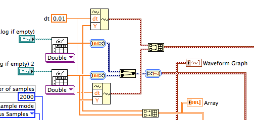
Why are you converting complicated to and from DDT to get a picture of wave forms when you don't provide timetable information? Use Waveform build and build table as shown or just use the DAQmx Write DBL 2D value.
As Henrik, I fear that your data are not what you expect it to be. Put a graphical indicator or a table on the wires going to DAQmx writing to see what you have.
Lynn
-
How to compare an analog signal to another analog signal to see what signal has a higher value? I want to display the result on the façade with LED indicator.
This will make a simple comparison of A > B. If your code is more complicated then you must set up a system of producer-consumer. You can find examples of this in the supplied examples.
Here's a sample:
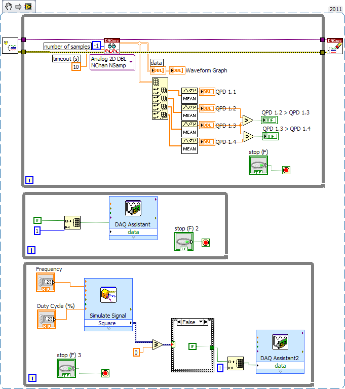
Maybe you are looking for
-
Wireless card replace dv6-3030er
Hello! I altheros great wifi adapter and want to replace it with the Intel card. purchased 62205 and getting the error with the incompatibility of the wireless adapter. where can I found information on the cards supported wireless? Thank you
-
I get a message that my Vista Windows 7 is not genuine and I need to activate it. I had Windows Home Vista for about 6 years, I bought the computer. This message has suddenly started to appear today. It requires a product key that I don't know. How c
-
Hello Just bought AIR-LAP-1252AG-A-KP 2, APS. I noticed that there are external antenna connectors. I have loked in the Doc, but impossible to find the info I'm looking for. I want to use inside a gym room and wondering if they will work without exte
-
I created a page with several interactive reports. The main report at the top is a report of "companies". All other reports are partial reports (addresses, Contacts, etc.). I have a page that I put the value with javascript (company code) by clicking
-
Help with a custom calculation for rounding up/down in Adobe Pro
Hello! I've never written a custom calculation, so I'm lost; could someone help me please write one round to high-low a.50/.49 with this field name:CreditedTotalLocal + OtherHEFor example, if the value of this field, which is the result of the funct