analog input external trigger 6015
Hello
I was able to configure my 6015 to accept an external trigger to start a measurement of analog input (with a # set of samples and freq). However, what I want to do is to set up so I can send a 20 kHz signal to the trigger, and whenever the trigger detects the signal, the device would take a measure of the tension of each of the two channels. He would then save this memory on board and allow me to read the data later. That's what I can't figure out how to do.
If he put in place such as I have an asynchronous callback and read data after each pulse, it takes too much time in my application. I want to get a measure for each external trigger pulse (the freq may vary higher or lower, it's why I can't put just a freq - I need to use the trigger) and these data saved in memory on the card for me to pick it up later.
Is this possible with the 6015? Another tip? If so, can you please show a few snippets of code in VB.NET or c# .NET?
Thank you
Joe
Hey Joe,
I think that your application should work fine with the 6015. I mentioned only the buffer size as previous your post said 'I want... these data stored in memory on the card to grab me afterwards,' and especially supported in NOR-DAQmx devices (including the 6015, PCI E Series, the new series X PCIe and PCI M Series) don't work that way. They have permanently transfer data in a buffer in the memory of the host throughout the acquisition PC, and they have enough buffer on board to avoid negative/overflow buffer overflow errors at their maximum supported rate
Brad
Tags: NI Hardware
Similar Questions
-
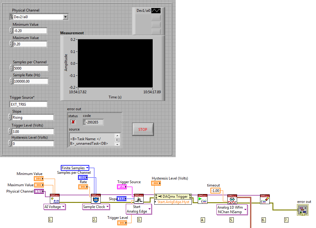
Source of external trigger PCI-4472
Dear all,
I have a PCI-4472 b I want to program to acquire a signal channel 0 whenever it recives a TTL signal throw the input external trigger.
I use a modified example but I don't know which is the name of the external trigger source. I always receive this type of error (for example if I connect to a string that contains "EXT_TRIG"):
Code: '-200265 '.
"DAQmx Start Task.vi:1 '.
Property: Start.AnlgEdge.Src
Value: EXT_TRIG" Task name: _unnamedTask
" The program I use is of this form:
First of all, this error means that I have no right external trigger source name entry?
If so, which one is the good name of the source of external trigger for NI4472B?
Thank you for the help
Hello
The error pops up because there is no channel named EXT TRIG. If you receive a trigger channel 0, I think that the best way is to specify the name of the channel in the "DAQmx Start Task. There is a terminal where you can specify the name of the channel and use that name to a string for the trigger input. I think this should solve the problem.
I referred to this knowledge base.
http://AE.natinst.com/public.nsf/webPreview/BEBB10D02D72798A8625736B0076B09A?OpenDocument
Also, looks like you have trigger 'start analog edge '. Since you want to get the TTL signal, why not try 'start digital dashboard' trigger?
Kind regards
-
I am acquiring several channels of analog voltage input at the same time, I need to send an output analog two seconds after the start of the entry.
I'm running an experience with accelerometers on a query table.
I start the trigger and the table remains still for two seconds, which allows a reference level for all sensors.
Then the output signal of the VI removes the break in the motor controller.
The speed measured by the encoder is sent to one of the input channels.In this way, our accel and speed data are synchronized.
After it acquired the analog input data out put must be reset to zero.
MULTI.vi I've updated the link above works of VI, I used a property node to solve the problem.
-
Hallo,
I use the following system:
- OR PXI-1044 with controller NI PXI-8109
- OR PXI-2564 switch module to turn on the monitor of my test device
- Data acquisition multifunction NI PXI-6259 to measure the signal that responded to the questionnaire jump
The two cards are the same - PXI trigger bus. For both, PXI-2564 and PXI-6259 I use DAQmx to set the reading and writing of the channels.
Now, I want to measure the time between the digital output, my unit turns and the analog input, which measures the response of my system.
I can't do work by myself, please help me!
I thank Ludwig.
Hi Ludwig,.
If you can't give us any VI we have difficulties with to help you.
Because I Donat knowledge how your program is mounted it is not easy to know where you should enter signals.
Here's a question similar to yours:
http://forums.NI.com/T5/LabVIEW/best-way-to-measure-time/TD-p/178704
and 2 external links:
http://www.ehow.com/how_8698983_measure-time-LabVIEW.html
http://objectmix.com/LabVIEW/385152-how-can-i-use-LabVIEW-measure-time-between-analog-pulses.html
-
9174 triggered output pulses and analog input synchronization
Hello
I have a cDAQ 9174 with a 9215 analog and a 9401 module. I wonder if this configuration is suitable for my use: a trigger digital extern is sent to the system to trigger a task of analog input, trigger a generation of pulses, with another counter, count of trigger events. Using two counters on 9401, it seems I have no left Terminal at the entrance of my trigger signal. The trigger DAQmx vi does not show counters entries in the list of signals; and if I select a PFI line, an error that says that the line is already in use..., I missed a few obvious solution? I have change my 9401 to a 9402 did?
Thanks for any help,
Vincent
Hi Vincent,.
So, looks like you need a single line to use as input to trigger events and another line to use for a generation of pulse output. This should indeed be possible, since the 9401 has 8 lines that are configurable nibble (i.e. lines 0:3 could be configured as inputs, while the 4:7 lines could be taken out, or vice versa).
However, a big caveat with the 9401 is that the lines must be reserved before each task is started. This is a limitation of the direction of the line is implemented in hardware and is common as customers when something they using the 9401. Explicitly reserving your tasks before starting must correct the behavior if that is indeed what you see.
Best regards
-
Hi all
I use a Board PXI-5422 generator of finished generation mode signals to generate an external trigger signal (PFI0) about every 5ms. There is a nominal 1.7µs delay of the input trigger for the start of the generation. That in itself isn't a problem (I can compensate for the delay), but there are up to 50ns jitter on this period, which is a problem. Does anyone know if there is anything I can do to minimize this jitter? (Incidentally, PFI1 exhibits the same behavior, but it is not a surprise)
Thank you very much
Hello GVR123,
I had a glance at the manual for the PXI-5422 and I found the note for the ' delay of start CH 0 analog output Trigger "which is indicated as"65 sample clock periods + 110 ns. With this information, I calculated that
1.7 - 0, 110 = 1.59
and
1.59/65=0.025 (bulk)
that points to a clock of 40 MHz. So I guess that's what you use.
25ns deviation (40 MHz) each side (50ns total), you see the expectation, as there is no way to ensure that the trigger falls exactly on a rising edge of the sample clock.
I hope this helps.
Kind regards
Michael S.
Technical sales engineer
NEITHER UK & Ireland -
Sync to external trigger in conjunction with a nearest pulse frequency device fixed...
I am writing an application running a scan frame. One axis of the scanner runs at a fixed frequency. I use a scanner high speed 5105 to get the data. The slow axis of the scanner is controlled by a servo with an analog input. I have will probably use an M-series card for analog control, but can also go with a 6713 (output only) or another Board. Fixed frequency Analyzer provides a clock line, I want to use to drive the 5105. In addition, the analog card must be synchronized in this. The entire system should be able to accept a trigger external devices, as it starts scanning at the edge of clock on next line.
I'm not quite sure about what would be the best way to do it. External triggering from other devices will be an indeterminate pulse width, so I can not just use it as a portal for the line clock. I am reluctant to do it in software (IE via the detection of changes on a digital line) because I want to be reliable started the next clock pulse. I have taken into account things like a counter/timer with a relaxing break, but which could lead to drift between the narcotics control and frequency scanner fixed. It seems just more complex that I think it should be, and it feels like I'm missing a simple way to do it.
Any suggestions?
Hi cshl,.
Good to know - the 5105 has a duty cycle of tolerance of 45-55% (mentioned on the page of the form), so that is why you cannot change clock speed from 3 to 12 MHz on-the-fly (though if you make small incremental updates over time, it would be theoretically possible).
With the additional information in mind, you might want to try the following on the 5105:
Use the external trigger as a trigger of departure (arm of acquisition).
Use the line as a signal reference clock (with a position of 0 samples for reference ~ 7500 are after initiation).
The problem with this is that you will have to re - trigger on each line - 5105 has a 2.4 rearm us time (also mentioned in the page on record). If this is unacceptable, another way that I can think of is to use a clock to external reference in PLL internal clocks of the bezel to. If you can provide a stable, a clock accuracy 50 ppm which is synchronized with your scanner within reach, would solve the problem of drift over time without having to re - trigger on each line (only acquire data continuously). This clock frequency must be between 1 MHz and 20 MHz in steps of 1 MHz.
We have no Council can take in an external variable clock up to 12 MHz (on-the-fly), but if you wanted to compromise a little bit the 6115 can enjoy up to 10 MHz, and has no obligation to cycle to 45-55% so it's maybe interesting look in.
As far as AO goes, I assumed that the clock line is declared after the quick scanner has completed his turnaround (ideally you do not update the zone of OCCUPATION during the lead time). If you have a signal Analyzer that you can use instead probably easier. If not, our peripheral series M and X series (but not the series AO 67xx) offer reference clock feature so if you go with the idea of reference mentioned above clock it may be easier to simply PLL the clocks together. These cards in a PXI chassis or are they PCI form factor?
I don't know what you mean by the sticking point about the need for two triggers. I think the idea is that we use the external trigger to arm the 5105 and clock line to trigger each record. However, if you do not need to generate a pulse double based on the clock of your line then you can use counters to do (our counters are redeclenchables with time to rearm in the ns range).
Best regards
John
-
How to synchronize the analog input and the output of two different USB data acquisition boards
Hi all
I have two tips very different USB NI USB 6008 case, which I use to acquire the data (analog input) and a USB of NI 9263 is a output analog only site I use to route a signal (in this case a square pulse). The reason why I use the outputs analog 6008 is because I need to deliver negative tension and need the full +/-10 v range.
Looking at similar positions, I'm pretty sure that I can't use an external trigger or a common clock, I also tried to use the timed synchronization of the structures but no cigar.
I'm including a quick vi I whipped showing how the jitters because of the lack of synchronization signal. The OD of the 9263 connects to AI in the 6008 in this example.
I talked to a specialist in the phone and tols me that's not possible.

-
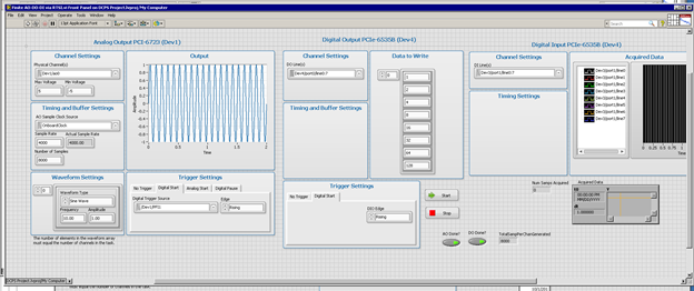
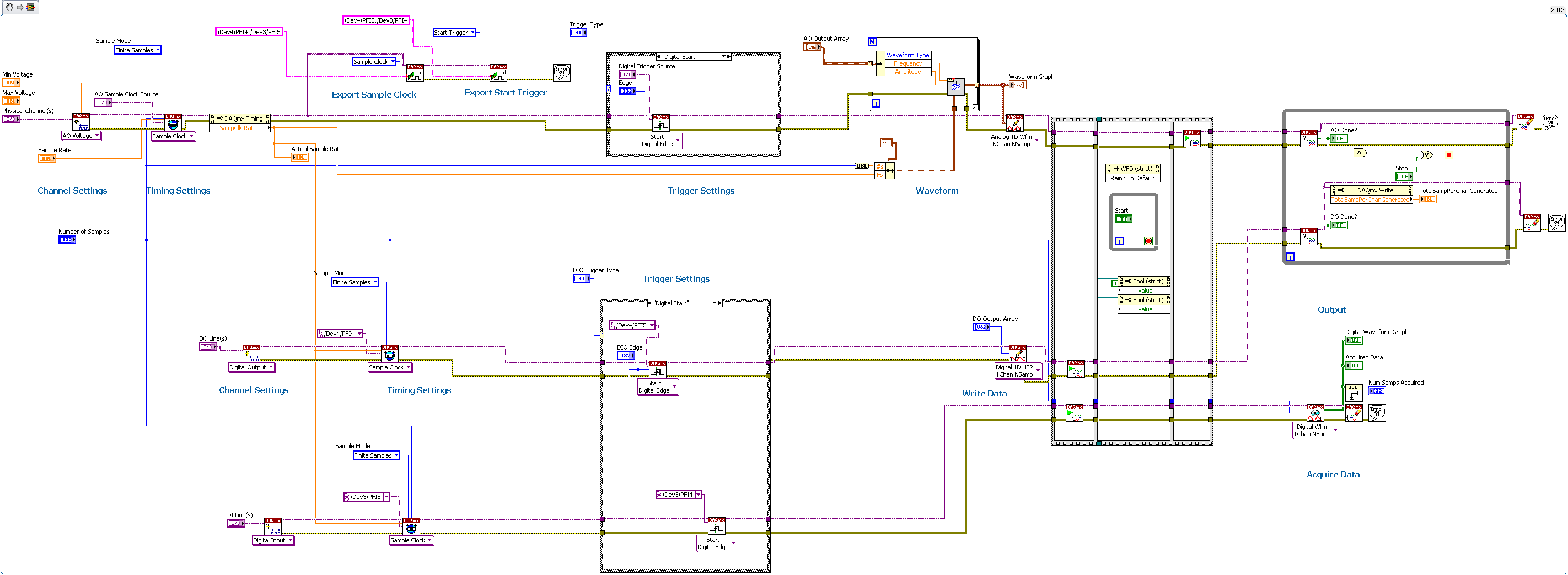
Several synchronization AO-DO-DI via DAQmx, external trigger devices
Having trouble getting the digital input to trigger analog output unit.
I have 2 AO cards (although I'm testing only with 1 device AO)
2 cards DIO - using one for output, one for input
All 4 cards are connected via a RTSI cable, and the cable is correctly condfigured in MAX, all 4 devices added to the cable.
I consider the AO the 'master' unit map In this test, I plead for a finite number of samples, and I'm outside triggering map AO.
As you can see, iI uses Signal export, export the AO and AO Start Trigger sample clock to DIO cards.
I'm using Labview 2012 on PC Windows 7.
The digital output is waiting for the AO trigger and appears off the coast of the AO sample clock synchronizing.
The digital input expires if I only fire at the time, so he does not expect relaxation.
any ideas? I tried all kinds of combinations.
Never mind! I solved the problem with digital input without waiting for the external trigger.
I just had to set the time-out waiting-1, so that he would never expire, and so he will wait for the trigger.
-
sample clock adjust external trigger
I am trying to use a source of external trigger non - TTL (square wave ~ 8 kHz from 0 to 1.4 V instead of 0 to 5 V) as the clock for an analogue waveform output voltage. Is there a way I can manually change the threshold used for the clock source so that I can get this working?
I'm trying to avoid having to solve this problem at the hardware level, which in my opinion, is to build a comparator circuit to generate a trigger signal TTL of my 0-1, 4 a signal trigger V square.
If not, is there a way I can generate a TTL signal that is synched to my trigger signal 0 to1.4 V ~ 8 kHz wave square using these maps NOR: PCI-6115 or PCIe-6323?
Thank you!
Cecinix, you are right. The sample of the signals clock are specified to be TTL signals, which means that the minimum thresholds of high voltage on the PCI-6115 and PCIe-6323 are respectively 2.2 V and 2,0 V. Digital/PFI input thresholds are listed in the data sheets of the devices, so that they are material defined. Unfortunately, given that all the digital inputs on the card you mention expect tensions TTL, it's something that you have to fix in the material. A comparator circuit could operate as a network of transistors of pull-up.
What generates the square wave? Would it not viable for generating a signal of TTL clock on your NI DAQ card and export this signal to the rest of your system? In general, a digital system is quite tolerant of extra tension a bit, so it's maybe easier than adding voltage conversion circuits.
Kind regards
William R.
Technical sales engineer
-
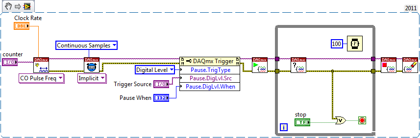
Continually acquire analog input, internal clock, break, Multiple device
I have a PXI chassis with 6 cards SMU-6363. I want to acquire data on the channels of each SMU-6363 map continuous AI, using the internal clock for timing. I need to use a trigger to pause reading of a DI on one of the cards SMU-6363 for a break and to reactivate the acquisition. I came across this example: https://decibel.ni.com/content/docs/DOC-12256/ , but keep getting error-201019 DAQmx start task "trigger break is not supported in a task to more devices. To configure the start of break in a multi-device configuration, you must use no more than one device per task and route manually clock in demand signals. »
The problem is that the configuration of I is made during execution by the operator. Sometimes they want to acquire data on one HERE through all 6 cards SMU-6363, sometimes they want to acquire data on each channel of AI through all 6 cards SMU-6363. What makes the task definition until manually route clock signals between devices for each rather difficult task.
Is there a simpler way to solve this problem?
Set a task to output counter - something like this:
Next, configure your task of analog input to use the sample clock output of the meter:
Best regards
-
What is the minimum response of analog input, through DSP online, output analog time?
Hello experts!
I want to know if it is possible to get a very quick response latency (~ 1 ms) sound recording (analog input), through online registration (DSP online), the presentation of his (analog output) processing, by using the DAQmx programming codes. My system of NEITHER includes NOR SMU 8135, SMU 6358 DAQ Multifunction controller and SMU 5412 arbitrary signal generator. I also have access to the latest version of Labview (2015 Version) software.
My project is on auditory disturbances, which inovles record vocalizations, manipulating the recorded vocalziations and then present the manipulated vocalizations. My current idea of how to achieve this fact triggered output voltage after reading the input using DAQmx Read samples. DAQmx Read output is filtered online and then passed as input for the DAQmx writing for analog output. For purposes of illustration, examples of code are presented below. Note for simplisity, codes for the trigger part are not presented here. It's something to work in the future.
My question here is If the idea above should be reaching ~ 1ms delay? Or I have to rely on a totally different programming module, the FPGA? I am very new to Labview so as to NEITHER. After reading some documentation on FPGA, I realized that my current hardware is unable to do so because I do not have the FPGA signals processing equipment. Am I wrong?
Something might be important to mention, I'm tasting with network (approximately 16 microphones) microphones at very high sampling rate (250 kHz), which is technically very high speed. Natually, these records must be saved on hard drive. Here again, a single microphone is shown.
I have two concerns that my current approach could achieve my goal.
First, for the DAQmx Read function in step 2, I put the samples to be read as 1/10 of the sampling frequency. It's recommended by Labview and so necessary to avoid buffer overflow when a smaller number is used. However, my concern here associated with the latency of the answer is that it might already cause a delay of 100 ms response, i.e. the time to collect these samples before reading. Is this true?
Secondly, every interaction while the loop takes at least a few tens of milliseconds (~ 30 ms). He is originally a State 30 late?
Hey, I've never used or familiar with the hardware you have. So I can't help you there.
On the side of RT, again once I don't know about your hardware, but I used NOR myRIO 1900, where he has a personality of high specific speed for the RT where I can acquire the kHz Audio @44 and process data. Based image processing is ultimately do the treatment on a wide range of audio data you have gathered through high sampling frequency and number number of samples as permitted by latency, please check this .
I lost about 2 weeks to understand host-side does not work and another 2 weeks to understand the even side of RT does not work for online processing (real time). Then, finally now I'm working on FPGA, where the sampling rate is 250 kHz (of course shared by multiple channels).
The complex thing with FPGA is coding, please check if the filter you want is given below as labview automatically generates some codes of some filters.
Most of them will work in 1 SCTL IE if your target has 40 MHz clock algorithm will run in 25 ns. That's what I was looking for, I hope you

See you soon... !
-
can you have set for the analog inputs points
If you install an analog input can you get set points that trigger an alarm or an engine that allows you to enable or disable
In SignalExpress you can use alarms to trigger recording on and outside:
Alarms Page - help of LabVIEW SignalExpress
Regarding disabling engines, SignalExpress is not intended to control applications. For controls, you should use LabVIEW or entirely a VI in LabVIEW, SignalExpress. To do the latter, you use a LabVIEW VI step in SignalExpress that will run a LabVIEW VI that performs control of treatment and the output you want. This way you could work in the SignalExpress environment for all the acquisition of data, and you should only use LabVIEW to program control VI (or screws).
-
NI USB - 6212 BNC analog input impedance matching
I just ordered a case NOR USB - 6212 BNC DAQ (should be delivered soon). I want to use to measure HV signals using a probe of high voltage of 1/1000 I have.
Now, datasheet of the probe (not a lot of info) says it has an impedance imput 100MOhm. I suppose that it consists of a simple resisitve divider, and if the ratio is 1/1000, I wait so to have a 99.9MOhm resistance in series with a 0.1MOhm resistance. However, the data sheet also specify that the probe is designed to be connected to an oscilloscope with an impedance of 1MOhm. As this input impedance is very low compared to the low value of the separator of resistance resistance, so I guess that the real resistance at the level of the sensor values 99.9MOhm and 0.11MOhm (to obtain the 0.99 and 0.1MOhm when it is connected to the oscilloscope for 1mW).
Therefore, given that the impedance of the USB-6212 according to the datasheet, the analog input is > 10GOhm, I expect to measure higher to true alternative voltages when connected to the acquisition of data from 10%. This assumption has a meaning?
What would be the best way to get around this? Do a calibration and correct the values acquired in LabVIEW code? Or should I add precision 1MOhm resistance at the same time to the acquisition of input data to decrease its resistance to entry to the value expected by the probe?
Thanks for your help!
Since you have a range of 1000: 1 I guess you also need bandwidth (I have a TEK 6015 A
), so you need based on the impedance input, a complex value, means he must not only watch but also the ability to input resistance (1 M). demarcation of the field probes have usually some elements of toppings to match the probe and the input scope. RTFM of the help of the probe
BUT a more serious point is that with your probe, you have a very high resistance. And if you look in the specification of the 6212 you will find on page 2 by mistake ppm in logarithmic scale graph! and even 100 k source impedance it not shown.
So I'm afraid that a simple 1 M on the DAQ entry can work if you're only measuring DC, and only if you use a channel on the acquisition of data. A workaround is an amplifier separate buffer with an impedance of good entry corresponding to the specification of your probe and a low output impedance.
-
Read the counter timeout in synchronized to count-analog input
Ciao, Giovanni.
The two tasks are run in parallel so there is no guarantee which task starts first. I suspect that when you are away from the counter samples, it is because the task of analog input before starting the task of counter. In this case, the task of counter would be ready to accept examples of clock and may be missing some edges of the clock at the time wherever he is started.
One way to solve the problem would be to use the wires of the error in order to ensure the time started the task of counter in front of the task of analog input. You can also use a sequence structure to do that.
The counter is sampled on each edge of the sample clock HAVE no matter what you set the 'rate' of entry to the. When you use an "external" clock (external to the task that is), the driver uses just the entry rate to set some default parameters (size of buffer for example).
If you have any questions, feel free to ask!
Best regards


Maybe you are looking for
-
WLAN is missing the MAC address and can not use WiFi
After an important virus corrupt my system, I got everything running except internet Wifi access. The configfree detects the unit, Wireless 2200BG, which is enabled and the latest driver downloaded from Intel, but he said nothing to the MAC address.
-
Low RAM speed to the Satellite Pro A200
Hi all! I bought the Satellite Pro A200-1SS with 1 GB of RAM (DDR2 667 MHz), which I've recently updated with a module 2 GB DDR2 667 MHz of Kingston. Problem is that this vista partition, which was 4.2 with only 1 GB module suddenly dropped to 2.2. E
-
What is wake my computer sometimes in the middle of the night?
The title says the question, with the qualification that HP destop is put to sleep every night and not wake with the movement of the mouse - a combination of keys is necessary. But something, I suppose a regular activity, he wakes up now and then. H
-
Miracast pro Dell place 8 question
I have a little android TV Stick MK808B that has a program WifiDisplay, which should act as a display for Miracast, I have an Asus android tablet that works with Miracast on and the screen of the Tablet is on my TV, but the custom of Dell connect, ar
-
Hello! How to change a part of checkbox label text style? TNX Best regards, SOAman