analog input offset USB-6009
Hello
I use several USB 6009 units and with some of them seems to have some lag in differential mode, I with 0 to 1V range. Grounded the two terminals with resistors as shown in the tutorial OR «wiring field and noise review...» "seems to fix the problem for some of them, but for those that I have not the slightest compensation first, the ground gives me offset. Can someone please suggest?
Thank you
DS
DS,
Please submit your question in the Forums of NOR. Are you trying to take a differential measurement? What features are you try to measure it and what channels the drop-resistance work with and what channels do they not work with?
Tags: NI Hardware
Similar Questions
-
analog input on USB-6009 - what potentiometer to use for this test?
Hello, I am referring to this video
http://www.YouTube.com/watch?v=rSNRG_Ddl1s
What is the resistance (ohm) the potentiometer used in the film?
Thank you
Luke
They know the author of video ...
Since it is connected to the output of 5V to the DAQ card, you don't want to use too low of a low value.
A pot more of 500 ohm must work safely. Exact value is not critical for this demonstration. Rear wiper terminal must be connected to the analog input, the other two legs go 5Vout and GND.
-AK2DM
-
Example of Code OR-DAQmx (C/C++) for playback of 8 differential analog inputs on USB-6215?
Are there examples using the API C/C++ of NOR-DAQmx in an application that illustrates how to read all 8 analog channels (differential) on a device USB-6215 or similar? I can find examples to read only one channel, but nothing for multiple channels. When I try to read all 8 channels, I get only entry on the first channel. Any help would be appreciated.
Kind regards
Bob
Brandon:
Thanks for the tips. I have it working now.
Kind regards
Bob
-
6009 outputs digital and analog input synchronization
Hello
I work in a program NI 6009. I want to leds by car with outputs digital NI 6009. For example, leads first will be on until what 200 micro seconds then second led will be on up to 200 micro seconds, and then first of all led will be on up to 200 micro seconds. I'll take led with photodedector signals and connect analog output photodedector input NI 6009. I want to synchronize the outputs digital and analog input and separate the first and second led signals the analog input for NI 6009 channel. How can you do with NI 6009? Please ADV
You can not do with the USB-6009 case. Its outputs digital are software with a maximum speed of slightly more than 100 samples per second. The outputs can produce 200 microsecond pulses and cannot be synchronized with the analog input.
You need a device with outputs digital hardware timed or counters that can produce a pulse outputs.
You can synchronize a bit digital output and analog input recording signal on an additional channel to HAVE. Will allow you to see the photodetector and LED the drive with the same schedule and such resolution as described by the sampling rate I. The maximum sampling frequency of AI on the USB-6009 case is 48 kHz that is shared by all channels. If you have two lights to led and photodetector two signals maximum sampling rate would be 48 kHz/4 = 6 kHz which is barely fast enough for your 200 US signals. For more than 4 channels, it won't be fast enough.
I suggest a simple oscillator circuit building and use it to clock a flip flop. This will give you alternating signals to drive the LEDs. You can use a line to reset the flip flop to give you control without the need for high speed.
Lynn
-
Acquiring bipolar signals NI DAQ USB 6009
Hello
The NI DAQ USB 6009 case is capable of acquiring biploar waveform? I have a signal generator that provides a 0.5V wave triangular amplitude in the NI DAQ USB 6009. The NOR-DAQ is connected to LABView and acquire signals using the LabVIEW express vi. The waveform that appears is unipolar. Terminal configuration is set to differential. Is the waveform which is seen. Thank you. Mary
Hi Tupaj,
See a voltage floating as this can sometimes be the result of a measure badly grounded. It would be useful, like Dennis, to know how you have this wired up. Please take a look at this guide to make sure that the device is properly connected to Earth:
Field wiring and analog noise - http://www.ni.com/white-paper/3344/en
In addition, information about the configuration of your software are also important. Here's an example of how implementing a fundamental mission of analog input for your 6009:
Video installation instructions - http://www.ni.com/swf/devzone/ai/
The example Finder has also several screws that already do it for you. If you work in 2012 before LabVIEW, look for Acq Cont & chart voltage-Int of the Clk.vi in the Finder of the example. LabVIEW 2012 will have a similar named VI voltage - Software-Timed Input.vi.
Kind regards
-
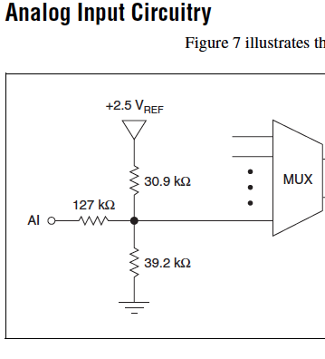
Cut-off for the 6008 analog input voltage
I am using the analog inputs NI USB-6008. The specification says they have a 144 k ohms input impedance. But it does not say what is the cut-off voltage. If you leave a disconnected and measure the voltage you will get 1.4 volts. So I guess it's the cut-off voltage, but it is not spec'd.
Someone agree that these Amnesty International isn't terminatied by 144 k - ohms to 1.4V? Is this in the documentation somewhere?
Figure 7 on page 16 of the NI USB-6008/6009 User Guide and specifications shows the strange input of this unit circuit.
Lynn
-
Hello guys,.
I am trying to create a simple VI to generate two outputs analog square with USB-6009. Each output supplies a LED and it is necessary that single LED shines at the time - so when Out0 is active, Out1 is zero and the other way around.
To get started, I created a VI in which the goods are made manually by Boolean and it works fine (square v1.vi of signal).
But I need the output to switch automatically after the amount of time given (I needn't of high frequencies, at about 1 Hz). To do this, I changed "square wave v1.vi" in "square wave v2.vi" and set the Structures of the case in an another While loop which would be timed by the wait function (ms). The idea was that the loop internal would turn the output rate of frequency while the outer loop would ensure a continued implementation of the programme. But the reality is very different and my low level of competence (this is my first VI) let me down. Could you please help me out of this? I appreciate all the advice.
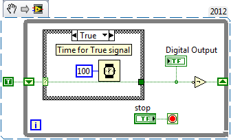
To summarize: The VI must be continuously running program that generates two dependent signals with adjustable amplitude and opposite phases (Out0, when active, Out1 is zero and vice versa.). Signals must be switched automatically to the given frequency.
Here's a simple flip-flop - while time the loop runs, the Boolean line connected to the digital output passes from true to False to True... with the schedule determined by the time you put in waiting for him (note that you can have regardless of the different times for the true = on and False = off case). Of course, the life of signal (represented by 'Digital output') 'inside' this loop - you have to put the 1 point 1Line DAQmx VI write digital Boolean inside the loop, or find a way (for example, a queue) to get the data between the inside and outside.
-
Digital and analog inputs simultaneously - NI USB-6009 and NI USB-6212 - ANSI C
Hello
I'm reading at all times and at the same time analog and digital inputs. Digital and analog samples must be sampled at the same clock and acquisition should be started (triggered?) at the same time (I don't want, after some time, analog reception more digital samples - the opposite is also true).
I found an example (in C source code) "National Instruments\NI-DAQ\Examples\DAQmx ANSI C\Synchronization\Multi-Function\ContAI-Read dig Chan" and tried to run with two USB cards: NI USB-6009 and NI USB-6212. Unfortunately, the two results by mistake, as described below:
DAQmx error: the requested value is not supported for this property value.
Property: DAQmx_SampTimingType
You asked: DAQmx_Val_SampClk
You can select: DAQmx_Val_OnDemandTask name: _unnamedTask<1>
State code:-200077
End of the program, press the Enter key to exit-Is it possible sync analog and digital acquisition in the paintings?
-If so, how?
Thank you
Hello tcbusatta,
Two of these modules, USB = 6008 and USB-6212, support only timed software inputs and digital outputs. This means that you cannot define material timing (like finished sampling or continuous) for these modules. Digital lines can be retrieved or written once to each call DAQmx read.
This means that you will not be able to get any type of synchronization tight between the analogue and digital channels. You will need a Board such as the NI USB-6341 in order to synchronize the AI and DI closely.
-
inputs and outputs analog digital usb 6009
I'm having a problem with my USB 6009 in labview programming. I try to read continuously from the analog inputs while having an event focused on digital output within the same program/vi. Basically, I need to taste all the time the analog inputs while having an event defined by the user (button control) to signal the digital inputs to turn on then after awhile. The event of digital output must be independent of the analog sampling system. I was throwing the "error already allocated resource" in most of the vi, I wrote to try to achieve. What is programmatically possible with usb 6009? I am at my wits end trying to do this and any help would be greatly appreciated (by myself and my boss). Thanks in advance for your answers.
RJ
-
With the NI USB-6009 analog input lag
Hello
I try to acquire analog signals with NI USB 6009 using LabVIEW. (The signal is 50 Hz of the functional generator).
However, the acquired singnal has dynamic splitters, which is NOT observed by my oscilloscope.
I have no idea why this phase shift occurs.
Any information is welcome. Thank you for reading.
An image file will not help. Post your real VI. If Firefox does not work, use explore or Chrome to fix your VI (s)!
You have here a Subvi, I don't see what's inside and how it is configured. In addition, this while loop is ridiculous: there is no button to stop him running. Never use the red button to abandon for a normal shutdown of a VI!
Why you have configured NChan NSample? Measure a unique signal, Yes? For example, use 1 channel only.
Edit: why do not you play first with an example given, delivered with LabVIEW?
Your LabVIEW, go to the Help menu--> find--> material and output examples--> DAQmx--> entry--> and open 'Input.VI - constant tension!
This VI allows to enjoy your analog signal.
-
Using the DAQ USB-6009 meter and an analog input voltage at the same time.
Hello
Currently, I'm reading the two channels of voltage with the USB-6009. It happens that one of the channels is the output of a digital coder, and it would be much easier to use it directly to the PFIO entry that is defined as a counter. The problem I am facing right now, it's that I can't use the DAQ Assistant to use the analog voltage to a channel and the digital channel counter at the same time. Once I put the DAQ Assistant to read the input from analogue voltage, I won't be able to add analog inputs. And as I put the DAQ Assistant to use the PFIO as a counter, I can add more entries to read analog voltage is.
I wonder if it is possible to solve this problem using the lower level data blocks? Another solution would be to read two channels in analog input voltage and that the use of Matlab to process data resulting from it, since I was not able to do the counting to work simultaneously with the acquisition in Labview to impulses.
Hope you guys can help out me.
Thanks in advance.
Using a simple wizard of DAQ is incorrect. You need one to acquire analog inputs and one for the meter.
-
Problem of analog sinusoidal input USB-6009
Hello
I am a newbie to Labview. I'm using Labview 2009 and USB-6009. I tried to use USB-6009 to display the input sinewave of function generator signal. First of all, the perfect sinusoidal looking at the frequency of 1 kHz, but when I changed the frequency of 10 kHz, the sinusoid turned into a triangle wave. When I test the input signal, I put the 48 kHz sampling and Terminal configuration is CSR. Is there a problem with USB-6009?
You really need to spend some time to study sampling and Nyquist theorem-not LabVIEW. To faithfully reproduce the shape of the sine wave, you must go to a sampling rate 10 times higher than your input frequency. With the 6009, i.e. limit the entry less than 5 kHz.
-
About precision of analog input of acquisition of data USB-6009
Hello
I have a problem where I'm reading a temperature signal (10mV / ° c) using the USB-6009 case, but a problem of accuracy of the input signal of the DAQ hardware. The temperature at room temperature reads at a constant 230mV (23degC) using a multimeter device, but with the DAQ hardware, I see the signal bouncing around to 25mV, + effects greatly my work.
I was hoping someone might have a solution to this as my brief search forums nothing have mounted. Is there a way to average this broad band to the extent of the input signal or from resovle anyway?
Hi mdzz,
What development environment do you use?
Here is an example of LabVIEW that should do what you need.
-
Analog input USB-6009 pegged about 300mV
I have an USB-6009 data acquisition module. I'm reading a (LM35)temperature sensor voltage. The sensor has three sons: one for the power, ground and one for the output signal. The output is in the range from-1 to 1 V. I have set up the 6009 for entry of CSR in this power range. I turn on the sensor with + 5 volts and ground and measure the output signal using a multimeter (a wire to the Earth, the other to the output of the sensor). Measures with the multimeter check the sensor works (output is environ.2 V indicating the temperature about 20 degrees C).
Then I set the output of the sensor to AI0 and fix the sensor on the 6009 GND ground. As soon as I do, the output voltage of the sensor passes approximately 0,3 v. I check this voltage with multimeter.
I tried several channels to HAVE two different data acquisition modules and several temperature sensors. The behavior is always the same (pegged at 0.3 V voltage).
Any ideas what might be happening here? Do I need to be concerned with the adaptation of impedance for this type of installation? Thanks in advance.
I now have this job. I have used CSR, connected the sensor Vout to AI0 +, connected to AI0 + to ground through a 1.5 k resistor. V connected + sensor for external power supply (12V). Connected to the ground on the sensor on the ground on data acquisition. I have no idea why it works, but the other solutions posted are not. As long as it works, I have no complaints.
-
Hello!
I develop a LabView program that I need to run a code every time + 24VDC signal from a digital sensor is detected. I intend to use my NI USB 6009, but as far as I know, the analog input is limited to + 20V in mode set (10V max in each pin). I was looking for in the data sheet and saw that data acquisition has a +-35V overvoltage protection, and then I thought: I just need to start my code when it comes the signal would be possible to connect my + 24VDC to the analog input of my DAQ withouth damage it?
Thank you!
You can use a voltage divider (resistances, one about 20 k sensor to HAVE and 10 k here forever, if your output of the sensor can handle this load), or in the simplest path one resistance 100 k (that will limit the current entry) and a 4.7V (for a digital input) or 9.6 Z-Diode (to HAVE) to limit the input voltage.
More protection would be an opto-Coupler, the 24V with a player of resistance 10 k out of the hitch and the LED has 10 k (or 4.7 k) for 5V (6009) pullup.
Maybe you are looking for
-
the sum of the time of loop iteration.
Hello I need to estimate a time every time through the loop. The time is different (depending on the counter triggers). I need to estimate the time of each simple iteration and add the last time with the current iteration. For example the first itera
-
Quisiera saber if there is a demo written conexion y manejo y/o c# propiedades con radarcube, decir, an example representativo
-
I am trying to hook up a TV with S-Video with my laptop. I plug the cables & when I go to the screen & my 2nd monitor/tv is not an option. It's only as 1 to my laptop screen. I'm trying to detect & still no solution...
-
How can I fix the error "searchfilterhost.exe" which keeps closing down of my computer?
How can I fix the error "searchfilterhost.exe" which keeps closing down of my computer?
-
Problems with Internet Explorer
Hello: Why is it whenever I go to my website to view jobs career opportunities that I get the message about a problem caused the program blocking to work properly? I finished the DEP and it still cannot afford to go to a specific section of my websi