analog input PCI-6251, implemented
Hi all
Can I set the analog inputs of the PCI-6251 in configuration of mix (some in differential mode) and others in single ended mode. Because in my set up the differential option is grayed out.
Thank you
dphan128
Yes, you should be able to do. You have 16 analog inputs. Differential, you will use two of them per channel. See the manual of series DAQ M. you can program channels on a M Series device to acquire with different
reference to the ground. To allow m
ultimode sweep in LabVIEW, use OR-DAQmx create
Virtual channel.VI of the API OR-DAQmx. You must use a new VI for
each channel or group of channels configured in another mode of entry.
Don't forget that for a premium that you would for example wire HAVE 0 to the + side and AI 8 - side. So now you can not use the AI 8 for simple nerve. HAVE 1 corresponds to the AI 9 etc. until 7 AM, GOT 16.
I hope this helps.
Tags: NI Software
Similar Questions
-
Strange problem with analog output PCI 6251 and BNC-2110
I'm controlling current source of third parties using the connectors of analog output on my card PCI 6251 and BNC-2110.
The current source needs an input signal of 0.1V. I tested it using a battery, the potentiometer and the voltmeter, and by manually adjusting the voltage of power current works - current output with control voltage scales according to the specifications and is relatively stable.
The data acquisition card works too - when I connect a voltmeter to the AO0 AO1, the measured voltage corresponds to the target with great precision value.
But when I connect the current source of third AO0 AO1 data acquisition card, the measured output voltage drops and fluctuates. This applies to both channels of the AO.
I wonder what is the problem here. I suspect it could be a matter of the grounding - the current analog control of the source is an entry with two floating terminals differential. I tried to return the switches FS/GS on the BNC-2110, but that makes no difference.
Anyone knows similar behavior? Does anyone have any suggestions?
-
Problems with timing of analog input PCI-6111
I'm reading the analog input of a PCI-6111, who receives a square signal of 1 KHz with a cycle of 50%. I put the sampling frequency to 1 MHz and wait until the data points are 1 usec outside. When I check the signals received, it appears that the duration of each period of the square wave is 1.22ms instead of the expected 1.0 ms.
The following is a snippet of what I tried:
int NUM_SAMP = 10000;
DAQmxCreateTask("",&mTaskHandle);DAQmxCreateAIVoltageChan (mTaskHandle,
"(/Dev1/AI0","",DAQmx_Val_Cfg_Default,-10.,10.,DAQmx_Val_Volts,null); "
DAQmxCfgSampClkTiming(mTaskHandle,"",1000000,DAQmx_Val_Rising,DAQmx_Val_ContSamps,NUM_SAMP);
DAQmxReadAnalogF64(mTaskHandle,NUM_SAMP,10.0,DAQmx_Val_GroupByScanNumber,mDataBuf,NUM_SAMP,&numRead,);
Can you tell me what I am doing wrong?
Hello SNL_NB_1167,
A good place to watch code you know works would be the finder of the example. "" "" Open the finder example and navigate to hardware input & output "DAQmx" analog measures ' tension ' ContAcq - IntClk.prj
Run this code and see if you get the same results. If so, then we would know that it's a hardware problem and not a problem with the programming. If you see the correct behavior, then you have code that you can shape your out of. I hope this helps.
-
Analog output PCI-6251-DAQ-200016 memory overflow error
NI PCI - 6251 DAQmx, AIMD-752 motherboard, dual core processor, a lot of speed and the ram running WinXP Pro & LabWindows/CVI
get DAQ-200016 memory overflow error when I try to generate a signal of analog output with a rate higher than about 32 000 samples/second (?)
going on what? I have never seen it before. Is this a problem with the motherboard? "It's the same product on the CVI code example" \Cont Gen Volt Wfm - Int Clk\ContGen - IntClk.cws.
If someone has had this problem, and is there a solution?
Thank you
PS: full text of the message reads:
Measurements: On-board memory precision passing. Due to the limitations of system and/or the bandwidth of the bus, the driver could not write data to the device fast enough to track the rate of output of the device. Reduce your sampling rate, change the method of transfer of data (from interruptions on DMA), use a product with more on-board memory or reduce the number of programs that your computer runs simultaneously. Task name: _unnamedTask<1> Code of State:-200016
Well, I found my answer. For later use, Olivia NI Apps Engineering suggested I have change the mechanism of data transfer by this Knowledge Base document:
http://digital.NI.com/public.nsf/WebSearch/C326F7D33CA6DB0E86256DFE008043B7?OpenDocument
... so I inserted the line of code between the creation of the area of OCCUPANCY of the channels and set up the example of clock calendar.
DAQmxCreateAOVoltageChan( ...

DAQmxSetAODataXferMech(TaskHandle,chan,DAQmx_Val_Interrupts);

DAQmxCfgSampClkTiming(...
now, I am able to generate output to a 2.35 MS/sec... max sampling frequency not quite the 2.86MS / sec indicated in the specification 6251, but close enough that I'll stop complaining

-
Output TTL triggers analog input with PCI-6251
Hello, I'm new to LabVIEW and have a question that I hope I can get a response on this forum. I am currently using a PCI-6251 DAQ card with a block of connection BNC-2120. I would like raise an event on an input, for example a sine wave, which is connected to AI0 analog. Then I would send a TTL pulse train via the digital output. What I'm describing can be better understood by the images of this link:
http://zone.NI.com/DevZone/CDA/tut/p/ID/3017
In the tutorial page linked above, they do mention the card PCI-6251, but when I read the specs and compared, 6251 also has analog and digital Board, trigger functions, as well as digital I / Os... so I think he should be able to do what I want it to do. Can anyone confirm this? If anyone could help me by providing a VI that could do what I ask, just to help me get started, would be greatly appreciated. Thank you!
Hello!
Please post on the Forums OR! My suggestion would be to use build it digital Pulse - Retriggerable.vi found in the Finder for example of OR. Open LabVIEW, go to help > find examples > input/output equipment > DAmx > generating digital pulses > generate digital Pulse-redeclenchables. Change the type of trigger for this departure vi > Analog edge and make the source one line APFI (pin 20 of your card is APFI0). This will generate a pulse based on an edge similar to a level that you specify.
I hope this helps!
-
Analog triggering on PCIe-6251 using BNC-2120 on Mac Pro?
Hello all-
There, does anyone know how an analog trigger using a PCIe-6251 card connected to a box of BNC-2120 interface? I am running LabVIEW 8.6 on a Mac Pro OS 10.5.6 and my VI of analog data acquisition seems to work but hangs up waiting for a trigger. The trigger analog signal must be applied to the terminal APFI0 and the BNC-2120 contains no connector with this name. On the M-series cards, APFI0 corresponds to pin 20 on the map itself, but I was not to locate any information that shows how the pins of the connector BNC-2120 connect internally to different spring on its façade and BNC connectors. Sales people NOR recommended the BNC-2120 as the correct one to use with the PCIe-6251, interface box so I think that probably one of the many connectors on the front panel of the box is wired to pin 20. Am I wrong? I spent hours to connect signals to the box in the hope of getting a trigger, and nothing has worked yet. To make matters worse, reviewing the VI to trigger a data acquisition using a TTL signal connected to all of the PFI 0... 9 connectors on the BNC-2120 just causes of VI to give undefined error message ' specific 89136 route cannot be met because the hardware does not support it.» The specifications for the PCIe-6251 indicate that a digital trigger should be possible through the PFI connectors, so it's a puzzle. I have an interface BNC-2110 box in the case which turns out be a solution, nothing about it is named APFI0 either. Any suggestion would be of interest. Thank you.
-Ken1
Hi Ken,
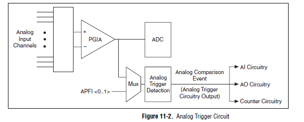
Unfortunately, the BNC-2120 doesn't have a connection available on the APFI your M series line. The BNC-2110 has this connection available.
A possible workaround is that you can trigger off channels of analog inputs as well. Here is a screenshot of the M Series User Manual that shows the analog switch-off circuits:
There are a few caveats to trigger off AI channels (mentioned in Chapter 11 of the manual)
If you use a trigger to start, the analog channel that will be triggered off the coast of must be the first string in your scan list.
If you use an analog input as a reference or a relaxing break, it must be the only channel in the scan list.
I hope this helps!
Best regards
John
-
Entered analog PCI 6251 not extent of tension of a mass flow controller
Hey,.
I have a data PCI 6251 M acquisition with a break in Council SCXI 1302.
I'm trying to measure a 0 - 5v analogue output voltage from a mass flow controller (check picture of PIN)
When I measured with a digital multimeter the voltage of the flow signal (PIN2) and common signal (PIN12) I get a stable right tension between 0 and 5v depending on the flow set up. I can control the amount of the charge by providing a data output set point PIN8 and common PIN12 of the 0 - 5V analog signal.
Now when I connect the signal flow PIN2 and on my DAQ signal common PIN12 AI and AIGND, I don't get readings on my labview VI of the AI. In addition the flow does not meet the setpoint voltage, it get stuck in a range of values no matter how I vary the OD 0 - 5V of data acquisition in setpoint PIN8 and PIN12 common signals.
I have to add that I tried different ports HAVE with results of sam, and I also tried to measure my supply voltage with my HAVE and all the good work.
It seems that the entry of AI affects the AO output voltages to my charge. What would cause this? That would be a problem of impedance adaptation?
Management or ideas are appreciated.
Thank you
Ali T.
Update for anyone that might interest you:
I not connected to the ground of the power of the mass of the signal of FJA FJA.
Once I did the acquisition of data reads all data as expected.
So it turns out not to be a problem of acquisition of data, OR at all, but a game of question for my part, as I suspect is the case with most of the problems.
Jeff Merci for your comments.
Ali T.
-
Problem with a precision of analog input on PCI-6111
Hello
I'm reading an analogue signal which varies from 0-11 V using a card of acquisition data PCI-6111. The signal comes from a Tube set (PMT) which is part of a microscope configuration, so it is very important that the resolution of the analog input signal be as wide as possible generate quality images. According to the data sheet for the PCI-6111, the analog input resolution is 12 bits, which should correspond to a sensitivity of ~2.686 mV for my voltage range.
To test this, I set up a task to analog input with a 0-11 V voltage range to read samples of an analog output, which I wrote a simple waveform. Since the 16-bit analog output resolution that I assumed that it would not limit the accuracy of this measurement. I have attached the VI I used for this measurement below. The analog input data are saved not truncated in a text file.
Analyzing these data, I found that the real input sensitivity is ~9.766 mV, corresponding to levels of voltage exactly 1126,4 and ~ 10 bits.
Is there a reason why the resolution of analog input is much lower that it is indicated on the card? What are some of the ways I could improve the sensitivity of this measure?
Best,
Keith
Sorry, when you mentioned the specs, I thought you already had them. If this did not come with your Board of Directors?
-
I use an analog input on a PCI-6224 and are having problems with the clock source
I use an analog input on a PCI-6224 and are having problems with the clock source. I'm trying samples of 16 different analog inputs very quickly. I have the sample mode: Timed Single Point material. The rate, that I am running is the maximum (250 kHz (15625Hz per channel)). I left the default clock source and trying to taste several times. The analogue input works for a short time (2-3 seconds) and then everything stops. I'm doing something wrong or is there something I'm missing? Any advice would be great.
That's how you samples using the sample clock clock. If you see a delay then something is wrong with how you track/data visualization.
Single point NI the hardware is for PID control with a real-time operating system.
-
Blocking of blue screen with the analog voltage (WinXP, PCI-6251)
Hello
I'm looking to solve a problem of blue screen with my measure blocking
application, which I am developing with C++. Blocking seems manifest
a little random after a variable amount (500-50 000) of voltage analog
measures. My application needs to make a huge amount of these digitally
trigger voltage measures after a certain period of time, and I'm using a
unique
task to do. The task is stopped and started after a single measure
is
which is done around 10 000 - 100 000 times per second. For this
because I do synchronized with the PCI-6251 map data acquisition and
one
Ztec oscilloscope card. It seems that the probability of blocking could be
associated with
the frequency of measurements of voltage that I perform.The
the app itself is multithreaded, but I'm blocking concurrent access
TO
the card with lock - all access to the card are behind a single mutexlock, so simultaneous access is blocked. In any case, all data acquisition
access
o the map is initially a single thread, which is dedicated to the acquisition of data
operations.I also did stress tests with Ztec scope map, which does not
result
in all the problems. I also disabled in order of acquisition of Ztec map data
TO
Make sure that it wasn't the card scope, the origin of the problems - the problem
persistent, so this seems to point towards the direction of the nidaq map.The deadlock appeared when I used the original supplied with drivers
the
card. I installed the latest drivers (removed the device from)
' Windows
Device Manager and your application Measurement & Automation, reinstalled), but the blue screen still appears.Blue screen gives me a few debug data, but it does not mention any
files .dll or something that would be of course point to a specific file (driver). I enclose at least partially matching code snippets.
Hello again! I've been in contact with a local support person, who suggested that I have use DAQmx_Val_FiniteSamps instead of DAQmx_Val_HWTimedSinglePoint. I don't have any other changes, but this (see below) and the problem disappeared, so this seems to be an acceptable solution, because I don't see at all why not do this way. (Thanks Henry!)
DAQmxErrChk (DAQmxCfgSampClkTiming (task_reader, NULL, 100000.0, DAQmx_Val_Rising, DAQmx_Val_HWTimedSinglePoint, 1));
DAQmxErrChk (DAQmxCfgSampClkTiming (task_reader, NULL, 100000.0, DAQmx_Val_Rising, DAQmx_Val_FiniteSamps, 2)); -
The PCI-6132 analog inputs does not
Hello
I have problems to install a PCI-6132 card on one of my computers. I am runing Labview 7.1 and DAQmx 8.6. In MAX, I opened the unit and test panels. The counters are working fine however the analog inputs always give v - 10 (-5 If the a - 5 min) without noise. the same on each channel. I have not connected any termianls and expect to see the noise around zero volts. In addition, the card fails the error calibration auto-200545.
I took an another PCI-6132 of a system works in this computer and had the same problem. So I guess the problem is the configuration of the computer or software. I try to reinstall the DAQmx and labview and the problem has not been corrected.
Nick Wagner
NOAA/ESRL/CSD
(303) 497-3924
-
Test the analog inputs in a PCI-6013
Hello. I m using a PCI-6013 OR DAQmx 9.1.1 with Labview 8.2 (sued) WinXP. The jury has undergone an immersion in water during a flood but was cleaned, recognized by WinXP and NIDAQmx.
I have run the Measurement & Automation explore and use the test under option OR-6013 'Dev1' panels 'devices and Interfaces. Here, I can see that the digital and clock output work perfectly (I can change the State of the digital channels and duty cycle and frequency of the clock). The problem arises when you try to measure an analog voltage. I tried on several cases not all analog channels using NRSE and differential modes (switch accordingly connections).
The signal comes from a (4 Hz, squares and sines, 5Vpp) signal generator via a CB-68LPR connector.
I only see something comparable to the entrance of singal when you use differential inputs (signal connected by J57 and J23) AI7, but the signal I see comes with 100 mVpp instead of 5 Vpp (I can see changes in the shape, every time that I have spend of a sine, square, ramp...). I also tried connecting J23 AISENSE (J62) and AIGND (J67), to avoid the problems of floating source. The same thing happens when enter and set up the acquisition by the vicinity of data in the Explorer of Measurement & Automation. I m using the reach of the signal in the different ranges, tried with 04:55, -1 to + 1, 09:50... When you configure tasks NIDAQmx I choose to read different samples (100, 1000, 10000) rate (100 Hz, 1 kHz,...) and combinations. Anyway, the input signal is always 4 Hz. I checked the signal with an osciloscope and I see it perfectly.
Is it possible to have the broken while the digital and general-purpose analog input clock outputs are OK? Y at - it a tip for the connections I should know about? Thanks in advance for any guidance!
Thank you both, KateB and MarisolM for your answers.
I made several the tests con señales DC y con señales senoidales, instalando placa en back different computers, y no obtengo resultados positivos, is spite of what el self-test selling well. Seems that the Plaça realmente esta fallando.
I did several tests with DC signals and senoidal, installing the card in two different computers, without positive results, even if the self-test is OK. It seems that the Council really works hard.
Are concentration cotización por su reparación. Gracias!
-
Synchronize the clocks of 2 PCI cards for analog inputs with e/s digital reference
I'm trying to synchronize the clocks of reference of 2 PCI cards so that the analog inputs are synchronized. However, my appilcation has also digtial e/s on two cards, and who apparently made the mistake DAQmxErrorResourcesInUseForRoute_Routing. This discussion describes a similar problem, but the solution was to just put the reference clock to the slave device, who had no other tasks running on it, so what mine does.
Is there way I can synchronize the clocks of refernce without interfering with the digital I/o?
Thank you!
PS: My application is in C++.
The reference clock is really a lower-level component that is shared by all resources on a given device. All tasks on a given device must use the same reference clock. So if you use DAQmxSetRefClkSrc for a task, you can use it to set the same value for your other tasks.
Best regards
-
PCI-6110 to change analog input range
The analog signal I want to measure is 24 volts and the maximum PCI 6110 is Volt.However 42, analog inputs that appear in the device under device NOR-DAQ traditional (old) configuration is 10 volts (single selection). I'm using LabView 7.1, DAQmx 8.6 and there is no function for allowed me to modify and change the analog device input range (Please find the print screen of the attachment). Can I know how can I change the analog inputs range?
I think that's what you're looking for:
S how to set up a data acquisition card series for the entry level so it does not Clip?
You must set up an appropriate gain so that the other ranges of voltage is displayed.
In addition, you can post on the forum instead of Labview data acquisition in the future, because the chances are that you will get better/faster responses there

Good luck!
-
What is the analog input of the NI PCI-6229 impedance?
I am trying to determine the effect of a 12 K resistor that is in series with an analog input of an NI PCI-6229 data acquisition card. Resistance of 12K seems to be part of a RC filter. I have a 0-10 VDC source this supply circuit. What is the impedance of the analog input of the NI PCI-6229 data acquisition card? If it makes any difference, the analog input is connected in differential mode with a 180K resistor to Gnd AI.
Thank you
RWB
Hi, RWB,.
The input impedance is classified in the specifications 10 GOhm. So, the effect of your k 12 resistance should be relatively low. Take care!
Maybe you are looking for
-
Satellite U500 - 1 6 - some missing drivers on Windows 7
Hello. Satellite U500 - 1 6, Windows 7 Ultimate edition.I downloaded the drivers of page service for similar model with i5 - 430 m because there are no drivers available for my own T - A still. But after installing the drivers, I found that the syste
-
Is it possible to HDR user on iPad 2?
I can't find HDR in my camera settings.
-
How can I restore my laptop to the original without a backup disk settings
Remember - this is a public forum so never post private information such as numbers of mail or telephone! Ideas: i have a laptop of hi quality and was not provided with a backup with the purchase.how disk do my original rear 2 portable format You hav
-
Hello Where can I find the newspapers printed to stderr when running the app on a Simulator? The QNX Momentics Console tab is empty.
-
Why Windows 8 is suddenly saying that I need to activate my window?
I bought my laptop since the year last of PCworld. Windows 8 is already installed when I bought my computer laptop everything was fine and I never had this problem, and my windows was activatedI am sure of that because I was able to customize my pc b