analog input quantified
Hello
The data entry in LabVIEW by my USB-1208LS is accurate, but the analog input voltage values are quantified (there are only a few repeating values: 0,691 0.696 0,701 0.696 0,701 0,691 0,691 0,691, etc..). I am able the tensions of four photocells, propelled by the + 5V of USB-1208LS. Each cell is measured in a different channel using the differential input mode. Is it possible to fix the quantification of data?
I don't know if it's a problem of LabVIEW, but attached is my diagram, in the cases where I'm not seized the tension properly.
Thank you in advance.
On the input range, the resolution of this device is about 5 +/-10 V mV, which is exactly what you see. The resolution is established by calculating the length of the total voltage range (20 V) and dividing by the number of steps or bins the A/D converter on this beach (2 ^ 12 = 4096). Yes, resolution = 20/4096 = 4.883 mV.
To get the best resolution, you will need to use a smaller range (if your signal wil fits into a smaller range) or get a DAQ hardware with a higher resolution, for example a 16-bit converter, or 24-bit.
Lynn
Tags: NI Hardware
Similar Questions
-
iMac with Thunderbolt - how to get the old analog inputs
I hang up my old Mac Pro in 2005. I used it to record video cameras and mainly music best of my plate rotating and stereo system - vinyl and CD disks via s-video and RCA cables and Firewire for Mac Pro.
The iMac 27 "new is primary Thunderbolt and I can't find a Thunderbolt conversion box so I can enter my analog input RCA and S-video signals. No indication on the Thunderbolt converters 'both ways' I can't exit analog in the iMAC, then the iMac as well?
They certainly run Final Cut Pro X on the iMAC, then how people get their old media and music in the machine?
I'm about to talk to the local Apple store, but the chances of finding someone who knows what they are talking about with the iMac, Thunderbolt and analog input is going to be a stretch.
Al Donn
You can probably use a converter DV firewire as a Canopus ADVC 110 http://www.bhphotovideo.com/bnh/controller/home?O= & sku = 349146 & gclid = CLSF0_qUnswC FQ8vaQod9VkFFw & is = REG & ap = y & m = Y & c3api = 187... and then an adapter firewire-crush.
-
Problem with analog inputs on sbrio 9627
Hey guys!
I have a problem in my Single Board RIO 9627.
I use 4 differential analog inputs (AI0, AI1, AI2 and AI3).
What happens is that when I place a sensor or even a button on one of the entries and nothing on the other inputs, it affects all other inputs, increase in the level of each input voltage.
Can someone tell me how to solve this problem in the hardware or software?Thank you!
Multiplexed inputs must have a low impedance! If you have pictures of ghosts.
Attach entries open to GND (or do not read
 )
)If you want to read switches or buttons use a pull upwards or downwards the resistance.
-
Analog input and output using 5640r
Hello world
I'm Christine, I'm implementing OFDM on fpga using 5640r.
The code that I have, which is good in the simulation using labview and also using 'nor 5640r treatment only' but I want to implement in "analog input and exit vi" so that I can send and receive on the same card 5640r
After so much attention in this regard, I am still unable to find the issue, then the soultion to this question. something that I am able to understand that maybe there would be some questions (ADC and DAC) clocks the clock setting
I have attatched that vi. Please take a look at
Concerning
Aqib
College of aeronautical engineering
Risalpur
Sorry
-
Input signal is set to +/-0 .5V when it is connected to an analog input
Hello
I have a difficulty connect an analog source to the analog inputs of my acquisition of data (USB-6215). The analog signal is output operational amplifier through a 10 k resistor. I wore the signal out of the amplifiers is 10V peak, I then move the probe across the 10 k (the analog input terminal) and the signal is clipped to +/-0 .5V. If I reduce the amplitude of the signals of source less than 0, 5V Ridge there is no clipping.
Maybe the analog input range the value +/-0 .5V which is causing this as a form of protection? I don't have a LabView to try to change the input range as I do just the wiring.
Analog source is connected to him HAVE 0 and the ground of the analog source is connected to the GND AI.
Thanks in advance.
J
Joel-
Have you tried to read the data through the data acquisition device? If that's what you try to do, I'm curious about what we read.
If you have measurement and Automation Explorer, go ahead and open a Panel to test for the unit and see what are your tensions.
Let us know how it goes.
-
6008 analog input - invalid values
Hello
Does anyone know how the analog input voltage 6008 invalid handles? Specifically, what happens if the circumstantial channel is configured for a 0 - 10 range v and a voltage negaitve, (-19.0) volts is placed on the analog input?
I use the library, C/C++, OR-DAQMx library. The call that I use to set up the port of AtoD is:
DAQmxErrChk (DAQmxCreateAIVoltageChan (taskHandle, AINPSTR, "", DAQmx_Val_Diff, 0,0, (float64) s_dMaxAnalogInputVoltage, DAQmx_Val_Volts, ""));
where: s_dMaxAnalogInputVoltage = 10.0;
and
DAQmxReadAnalogF64 (taskHandle, 1, 1.0, DAQmx_Val_GroupByChannel, values, 5, & not read, NULL);
to read the circumstantial.
What will happen if any illegal input voltage is applied. I know that everything is a wide range, so I don't talk about something like -60 to + 60 volts.
Thank you
-Neil shore
These specifications are in the datasheet of the product - link to it in the product specifications of the page tab.
And no, there is no error generated when the input is out of reach. Scaling the proper entry so that this doesn't happen. or if this is the case, your software recognizes that is higher than expected.
-
read the multiple analog inputs at the same time
Hi all
I use USB-6001 and want to develop an application to multiple tasks in C++. I try to read several analog inputs at the same time, but got some errors. To put it simply, I copy one of the sample code to read in analog data in a channel, and then turn it into function. Then I call this function to thread with the names of different poles (for example Dev1/ai0, Dev1/ai1) and I come across this error:
"The specified source is reserved. The operation can not be specified such complete"code of State-50103
I have search the forums, this may be because I use the hardware timing in this function, and this material timing cannot be used simultaneously by multiple tasks. I may have to put all the lines, I want to read in a single task (such as Dev1 / ai0:1). This way I can read two lines at the same time. However, when I try this, I encounter another error:
Status code "buffer is too small to contain the data read" - 200299
So here is my question, what should I do if I don't want to read the multiple analog inputs at the same time? Is the thing that hard time cannot be used by several true task? If I have to read several lines to a single task, how to set the settings?
-
How to compare analog input signals?
Hi all
I use PCIe6363 DAQ to collect the analog input signals. Mode of input signal is continuous and single channel several example. The sampling frequency is 2 ms/s, number of sample 100KS or less. This means DAQ 100KS of collect and draw a line/curve. I want to compare the two curves. The problem is DAQ continuously collects data and plot also continuously. Would you please is it possible to compare the curves of this operation continuous operation. The main goal is to justify whether or not the signal of incomeing maintain consistency.
Thank you very much
Azim
You can store a waveform in a shift register. Then you have in memory compared to the new waveform.
-
Several analog inputs seem to change any of the other (details DAQ: 2120 BNC and 6062E)
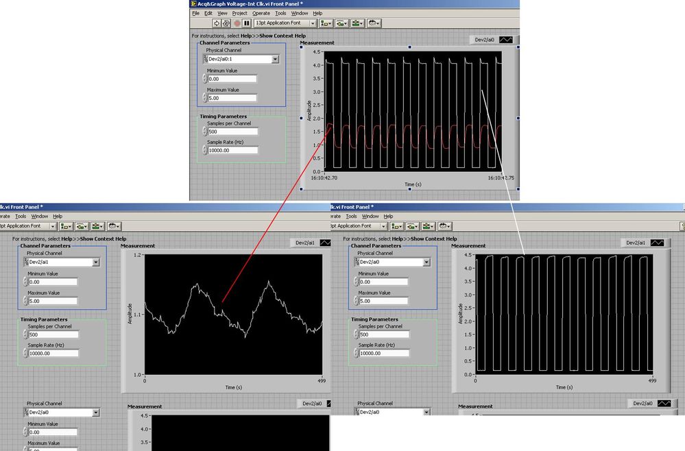
I use the BNC 2120 DAQ board connected to the data acquisition card 6062E to record two analog inputs. An entry is connected to ai0 and the other at ai1. Example vi: "Acq & graph int clk tension" has been used to measure the two entries with the value read NChan NSamp vi (channels being dev2 / ai0:1). The output is the top graph in the image. However, this seemed a bit strange to me that one of them should be modulating with a different frequency. When I record both entered individually (two in low pictures) they are indeed different since the entries shown in the top graph.

Why this would be the case, and how can I overcome this to measure the real signals?
Thank you!
The E series card takes the samples as soon as possible. Thus, for example,.
If you have 16 analog input channels but you only read of
channel 0 and 1, the map will show the channels 0 and 1 right
After and then wait 14 'ticks '. What's that little run-in
the origin of the afterglow.
I think you can get the card to wait a certain
number of ticks with a property node. I have attached a screenshot. You
can find the property node in the palette of functions >
Measurement of e/s > NOR-DAQmx > node Timing. Expand it
Property node so there's two entrances. The properties are in
Left click on the node and going more > converted >
Its properties delay units and sampling clock delay and delay that
you want.If the phase is important so the above is not the best
the option because it causes a delay in phase. So, if you need true simultaneous
sampling, then you will need different hardware. The S series is everything
simultaneous sampling.Or, rather than the Delay property and delay units, try the Rate property
find more > converted > rate.If this is not
work either, you can move the second signal source to, say, AI8 and
Connect everyone to the ground. Readings for these, but just do not take into account
the data. In this way the ADC will sag to the ground at the time where that can happen
the second string in the way so that you should not see this frequency
ghosting on the other channel. -
Problem with a precision of analog input on PCI-6111
Hello
I'm reading an analogue signal which varies from 0-11 V using a card of acquisition data PCI-6111. The signal comes from a Tube set (PMT) which is part of a microscope configuration, so it is very important that the resolution of the analog input signal be as wide as possible generate quality images. According to the data sheet for the PCI-6111, the analog input resolution is 12 bits, which should correspond to a sensitivity of ~2.686 mV for my voltage range.
To test this, I set up a task to analog input with a 0-11 V voltage range to read samples of an analog output, which I wrote a simple waveform. Since the 16-bit analog output resolution that I assumed that it would not limit the accuracy of this measurement. I have attached the VI I used for this measurement below. The analog input data are saved not truncated in a text file.
Analyzing these data, I found that the real input sensitivity is ~9.766 mV, corresponding to levels of voltage exactly 1126,4 and ~ 10 bits.
Is there a reason why the resolution of analog input is much lower that it is indicated on the card? What are some of the ways I could improve the sensitivity of this measure?
Best,
Keith
Sorry, when you mentioned the specs, I thought you already had them. If this did not come with your Board of Directors?
-
How to merge and write analog inputs, and export data to a tdms file?
I have a vi who writes analog inputs in tdms files. I also want to write the analog output signals, which are 2d table entries in the same PDM file with additional columns representing the analog output signals. How can I get this feature?
Ashaironix wrote:
Hey Crossrulz,
So you're saying that writing two files tdms with entries as HAVE and AO, will write everything in a file single tdms AOs and Ais?
N ° you write in the same file, just different GROUPS. TDMS is a hierarchical data format. You have the file, group, channel. Waveform data will actually in the channel data. But you can have metadata on any level. So, I do a group I and a group of the AO.
-
Frequency measurement of analog input using DAQmx C APIs on SMU-6341 map
Hello
I use Linux DAQmx and attempt to measure the frequency of analog input using the map DAQ SMU-6341.
There is an ANSI-C frequency measurement example:
/ usr/local/natinst/nidaqmx/examples/ansi_c/Analog_In/Measure_Frequency/Cont_Freq-Int_Clk-SCXI1126
However, the call to DAQmxCreateAIFreqVoltageChan results in the following error:
DAQmx error: selected physical channel does not support the type of measure required by the virtual channel you create.
Create a channel to a type of measure that is supported by the physical channel, or select a physical channel that supports the type of measure.
Property: DAQmx_AI_MeasType
Required value: DAQmx_Val_Freq_Voltage
Possible values: DAQmx_Val_Current, DAQmx_Val_Resistance, DAQmx_Val_Strain_Gage, DAQmx_Val_Temp_BuiltInSensor, DAQmx_Val_Temp_RTD, DAQmx_Val_Temp_Thrmstr, DAQmx_Val_Temp_TC, DAQmx_Val_Voltage, DAQmx_Val_Voltage_CustomWithExcitationTask name: _unnamedTask<0>
State code:-200431
DAQmx does support the function of the frequency on the map 6341, or should we use examples of voltage and calculate the frequency manually?
Frequency of HAVE it is a type of channel that has been supported only on the SCXI module name of the example.
You will need to use a voltage input channel and calculate the frequency manually for your device.
-
reading of the analog inputs with RPC
Hello
Because LabVIEW can not handle this (in VI; the value that you have saved the excel file has not been the same, that I saw during the measurement...) This confused me for a long time
 ), I want to write a C++ program (IDE: Dev - C++) which can read & record 2 analog inputs of the NI USB-6009 box. For this, I looked for an example of National Instruments and I found a little. But my problem is that I can't even use any example, because it has always held a mistake, after that I have compiled and started.
The error once the task has been created and has the :-200220 error number with the description "device identifier is invalid. But I do think that its invalid, because it's the xP example
I must say that I am new in programming C++, which means I could have a rookie mistake. And I couldn't find documentation or something for the NOR-DAQmx library.
Someone has similar problems with DAQmx and C++ and know how to fix? I don't really know what I can do now without a working example or documentations...
Hi Mario
It's the same thing. You didn't just save all of the data:
Please take a look at my comments in the attached VI.
Christian
-
NIDAQmx to simulate synchronized analog input from two devices of simulations?
I would test synchronized analog input from two MFDs simulated from the NI6225. I created two devices of simulated able NI6225 & Automation (M & A) and tagged the first NI6225a and the second NI6225b. M & I created a RTSI cable configuration and added both simulated devices. However, when you call NIDAQmx C functions in my test code, I get an error condition indicating that the simulations devices are not synchronized. Before continuing, I would like firstly to confirm if NIDAQmx is designed to
simulate synchronized the analog input data of two devices of simulations. If this isn't the case, then it will explain the error condition that I have encountered in my test code.
Thank you
Ian
Hello John and Jared,
If I remember well used to support the simulated synchronized devices. I ran various tests this week, but all fail. I'm going to order/install a RTSI cable and test with physical devices.
Thanks for your help. I close this post.
Ian
-
Hallo,
I use the following system:
- OR PXI-1044 with controller NI PXI-8109
- OR PXI-2564 switch module to turn on the monitor of my test device
- Data acquisition multifunction NI PXI-6259 to measure the signal that responded to the questionnaire jump
The two cards are the same - PXI trigger bus. For both, PXI-2564 and PXI-6259 I use DAQmx to set the reading and writing of the channels.
Now, I want to measure the time between the digital output, my unit turns and the analog input, which measures the response of my system.
I can't do work by myself, please help me!
I thank Ludwig.
Hi Ludwig,.
If you can't give us any VI we have difficulties with to help you.
Because I Donat knowledge how your program is mounted it is not easy to know where you should enter signals.
Here's a question similar to yours:
http://forums.NI.com/T5/LabVIEW/best-way-to-measure-time/TD-p/178704
and 2 external links:
http://www.ehow.com/how_8698983_measure-time-LabVIEW.html
http://objectmix.com/LabVIEW/385152-how-can-i-use-LabVIEW-measure-time-between-analog-pulses.html

Maybe you are looking for
-
Re: Transfer of photos on eBay from my laptop Satellitle L450 - 16 q with Win7
My old laptop broke so I bought a new and now I have the headache that I can't download the pictures to sell my stuff on ebayI found on the internet other ppl with the same prob, PC toshiba laptop windows 7 and not ebay download but there is no solut
-
Problem activating PBS Kids video
I bought and set up a new 4th gen Apple TV today. I was able to successfully download and install the PBS Kids video app unfortunately when I try to active service within the app, nothing happens. I click the icon 'Activate your Apple TV' and nothing
-
accidentally deleted files from a removable source, how can I get back them?
The files are not in the trash and I can't not find them nowhere, but im not so advanced in computers. I had also copied images to paste them into a folder, it is simply not allow me to copy because they are not found. any ideas anyone?
-
Hi I just bought the real cover of Sony z5 premium. However, I can't figure out how to work the windows? I need to download a gadget to do that work? And what other features does the coverage?Thank you
-
Install MDSM on 2008 Server Core?
Greetings, all. I intend to update some PE2950 systems connected to a MD3000 from Windows Server 2003 to 2008 Server Core system. I downloaded the latest CD of resources MD3000 (MD3000CD15.iso) and read the installation guide, which says to run setup