Analog output DNL value details
I have an application where I use a card PCI-6221 to generate a sinusoidal signal over a wide range of amplitudes (> 1000: 1). Obviously at low amplitudes, the waveform becomes very pixelated, but the harmonics generated by it are not a problem in this application, and I found that the use of a small number of steps of the ADC has surprisingly little effect on the amplitude of the fundamental.
What is potentially more of a problem is the DNL specification of +/-1LSB. This means (I think) that if my peak-to-peak amplitude waveform is 65 CAD not and he is riding on one of the glitches in the stairway of the DAC real amplitude might actually be steps 64 or 66.
My questions:
The DNL value technical or worse is stipulated in the average of plug? Since the device has guaranteed the monotony I think there must be worse, in which case there is no data on what is the distribution of the DNL error?
In the DAC in the 6221 the biggest mistake step usually gets to the point where the MSB changes state, which would usually be close to the point of zero?
If so, it would be useful to define the range of output + and - values to asymmetric tensions so my waveform is not sitting on the MSB switch point?
Thanks in advance!
Chris
Hi Chris,
You are right that the DNL worst case is ±1 LSB (where the guaranteed 16 - bit montonicity mentioned in the page on record). This is a 'classic' of the DAC manufacturer DNL distribution:
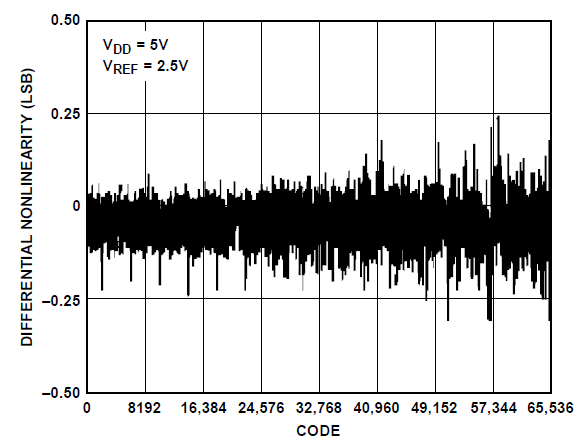
As for your second question, glitching may appear when the value of the DAC. This parasite is not included in the DNL specs (which represent a queue time). You are right that the most important glitch occurs when changing the most significant byte of the DAQ hardware (which is approximately 0V on the 6221, calibration function). Glitch is accounted for in the specifications OR as "Glitch energy" (see page plug link above), and you'll probably notice the value is relatively high on the 622 x. The 625 x and x 628 have much less power glitch due to the use of a different DAC.
If I understand your third question, the idea would be to adjust the range of the 622 x so that change MSB does not match 0V? Unfortunately, the 622 x only has the simple bipolar ±10V range available, so you can not adjust the range change where the MSB. You can, however, the power of the wave with a DC offset so that the MSB is never crossed, then use a filter to remove the continuous component of the signal (assuming you want the sine wave that is centered around 0V).
Best regards
Tags: NI Hardware
Similar Questions
-
Read analog output channel value internally
According to this you can read the values of analog output of return without having to physically connect the wires.
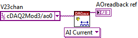
By using the technique described in the example given (DAQmx_Read_Output_Internal_Channels.vi) I'm reading a current area of OCCUPANCY on my compactDAQ cDAQ-9174 with a module of analog output current OR-9265.
The output channel is created in MAX and my vi can write values to him without problems
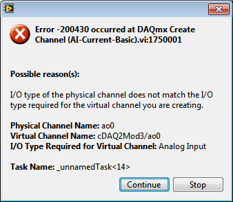
But when I try to create an analog input channel to read the output, an error occurs.
What I am doing wrong?
This is not supported by my hardware?
Or is the example given in the above incorrect link?
The example is 10 years old. Maybe, it does not work in LV2013.
Hi Jocker,
The link was not attached to your message, but I guess that's it: http://digital.ni.com/public.nsf/allkb/CB86B3B174763C3E86256FFD007A2511 as there the example of vi you mention.
The error you are getting is due to the use of the channel for analog output and trying to configure the task as a task of entry. You must use _aoX_vs_aognd as the channel of the task rather than on the output channel. This compares to the ground for the analog output values.
The NI 9265 is not on the list of the C Series modules that have internal channels:
So I guess that the module is not able to compare its output to ground. He would appear in the dropdown of the channel names if available.
Pete
Applications Engineer OR
-
Incorrect value for analog output USB-6008. Cannot not out more than 3V
I use USB-6008 analog IO, but the analog output (AO0 or AO1) can go up to 3 - 3.5V. The output can follow accurately the value of 0 to 2, 5V, but then he start the values adjusted trolling and not can not spend you 3.5V exponentially.
The only strange thing the entire circuit is that I connected all patterns (analog source and I/O 5V) between them, but I don't see what affect the output.
Kind regards
ISSOKO
Thanks for the quick reply Ana.
It is not the Council NOR, nor the Council of motorization. Apparently, the interface for motor control (motor spirit C: solutions - cubed.com), load the analog output. A tension following actually isolated op amp output USB-6008 and solved the problem.
Best regards, ISSOKO
-
the time of acquisition of data - how to calculate the rate of analog output
I want to calculate an acceptable rate of analog output, one that is taken in charge by material (PCIe6353), without the rate being changed by the VI DAQmx Timing (sample clock). The final objective is to have a rate of analog output that is an integer multiple of the analog input for precise frequency, since the sinusoid AO's amplifiers, which have a ringtone when AO updates occur.
According to 27R8Q3YF of the knowledge base: how the actual scanning speed is determined when I specify the rate of scanning to My d..., the rate is revised as needed by calculating the rate of clock / asked for advice, divide the result rounded downwards and upwards in the clock of the Board and use the one that is closest to the requested speed.
If 'Embedded clock' is selected, which is the result "Council clock. DAQmx sample clock timebase Timing node - SampClk.Timebase.Rate says 100 ms/s. However, for a rate resulting from the update of 2.38095MS / s, the divisor of the time base timing node - "SampClk.TimebaseDiv" gives a value of 42. 42 x 2.38095 M = 99, 999, 990, where it should be 100 ms/s.
How to calculate an acceptable rate of analog output is supported by the hardware? I have other plates, in addition, a general method would be appreciated.
I haven't worked all the details yet but noticed a few things that may be relevant.
Req AI rate isn't a whole ditch 1E8. It is used to determine the rate of the AO.
There is no check to ensure that the rate of the AO is an integer division.
It seems that you have the right idea, but the implementation is not yet there.
Lynn
-
cFP-AO-200 analog output module (error-33180)!
Hello everyone
I use the CFP 1808 Bank as well as other such modules that HAVE 111 and enter I-110, I recently bought a Module AO-200 out of the currents of the order of 4-20 mA, I connected the module to the Bank and updated the device of the MAX Software, then I opened the Getting Started/Analog Output.vi leave examples in Labview to test 2011 map the VI returns an error with the code 33180 for me, I don't know what the problem is, but I tested the card with the MAX and wrote the values to it successfully.
Can someone tell me what is the problem with my VI
Thank you
I was able to reproduce your error. You must select 'All' in the Point IO Point field for this vi.
-
How to control the two analog outputs at a time
I'm new to LabVIEW and have some problems in DAQmx with control outputs analog multiple.
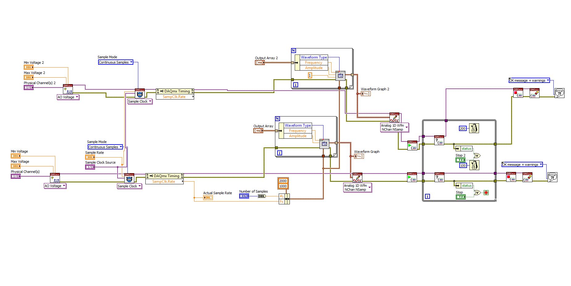
I want to set up a platform using BNC-2110 and PCIe6363 to control two rotating mirrors. The problem that I can only give an output (AO0 or AO1) at a time and I really have no idea how revise my LabVIEW diagram to control two outputs at the same time I met. I tried to change the outputs and it keeps a mirror turning instead of the old. Could someone help me with my problem and I would really appreciate. This is my blocked diagram and front.
Hi zrmaker,
As mentioned by RavensFan, you should not create 2 analog outputs different tasks if you use AO0 AO1. To your façade > physical control or the channels > select the drop-down list of the control channel physical (s) > Browse > hold down the CTRL + select the AO0 and AO1 > Select OK. Once this is done, you will see that your control or the physical channels has the following input values: "Dev1 / ao0:1" which means that you will access to AO0 AO1.
In regards to writing DAQmx, simply select Analog > multiple channels > samples multiple > 1 waveform (you should get the following: 1 d Analog Waveform NChan NSamp). Once done, you can just use table build to combine 2 different waveforms and plug in this table to DAQmx writing output. The first index will be the output for AO0 value and the other will be for AO1.
You can check this link on how to read or write from several channels: http://digital.ni.com/public.nsf/allkb/0C1ADEF06A54AB2D862575040066FD51
Additional reference:
http://www.NI.com/white-paper/2835/en/Hope that helps.
Warm greetings,
Lennard.C
-
read the output of a path of analog output current voltage
In DAQmx if you are unsure of the status of a digital output port, you can take a reading on this subject. When I try this on an analog output, I get an error. Is it possible to query the status of the output of an analog output? I realize that I could follow the State with a variable, but a direct reading would be really handy.
Hello, GIS.
There is no way to read the output in the AO modules without wiring physically the signal to a module to HAVE. You are able to use a variable to read the current value of the output, as you mentioned earlier.
Channels AO multifunction boards, however, can be read through tasks of entry by rounting in-house channel to read ao vs aoground.
Lisa
-
Hello
My question is about the analog output (0 - 10V) of the myDAQ unit.
On the card, you can read:
"Overdrive Protection +-16 V forever."
Lets imagine the worst case: 0 V output DQA, but outside a battery or anything else is connected with 15 V to the analog output.
Fact an "unlimited" current in data acquisition or protection 'Overdrive' works here and the material is safe to destroy?
The background: I want to OD are protected from transient voltages and toilet on a simple zener diodes clip or a tvs diode...
Thank you all, Markus
Markus,
To use a zener diode as protection, you must also have an impedance of current limiting in series with the source against which you are protecting. The manual for the device of maDAQ indicates that the lines of the AO are pushed by OPA1642 op amps. TI the MSDS for this unit shows the current limiting internal ~ 36 my short circuit with Earth and a thermal shutdown circuit that tries to protect against the terms of overpwer.
However, under your 15 V battery, 11 V zener and 0 V programmed DAQ exit, the situation may be different. The current from the battery through the zener will be limited by the impedance of cables or any type of resistance on the line. This has no direct effect on the myDAQ device, but it will probably destroy the zener unless resistance limits the current to a lower maximum current nominal zener. As long as the voltage at the output of the myDAQ is lower than the internal supply voltage (+/-15 V), on the OPA1642 current limitation should apply. With 11V applied to the output and the value set to zero the device would probably be to try to sink the maximum current for-15 V power supply. Which translates to a dissipation of power of more than 900 mW, which exceeds the rated capacity of the op amp. Themal protection should, in principle, reduce the current to a level that does not exceed the thermal limit under development.
This test can be a costly process. The unit may be destroyed. Given that the maximum current specified for an analog output channel is 2 my and the maximum voltage is 10 V, I would consider a series resistance of perhaps 1000 ohms and clamping schottky diodes at the + 15 V and - 15 V power supply. This will limit the current to 10-20 my in all conditions you have mentioned and would also provide protection to the case where the battery is connected the myDAQ device is turned off. He alsoe does not care about the polarity of the external source. It will drop the output voltage according to the load impedance. If this should be used in a student lab, the calcualtion of this decline is something they should be doing anyway, and would be a small price to pay for protection.
Lynn
-
Bad analog output help Every_N_Samples-NI-9263 cDAQ-9172 chassis (works with cDAQ-9178 chassis)
Hello
The NOR-9263 analog output voltage geberation works correctly with the cDAQ-9178 chassis but gives wrong result using the chassis NOR cDAQ-9172.
In the attached code example, a single cycle of a sine wave is composed of 40000 samples and came out in the background using Every_N_Samples at a rate of production of 5000 samples per second.
The output buffer size is set to 10000 samples.
Prepare us the buffer writing 10000 samples 1, then write the remaining data in the background using the Every_N_Samples callback.
Bug: Using the cDAQ-9172 chassis, to the 5000 s/s sampling rate with the help of an external field (or through closure to another HAVE), we observed that 1 10000 samples came out twice, followed by the rest of the waveform. The last 10000 samples are never exits. If you are working properly, we would expect to see 1 full cycle of a sine wave.The bug does not occur with the chassis NOR cDAQ-9178. I use the driver NIDAQmx v9.2.1f0 on Windows XP
The bug does not happen with simulation devices, so you will need to use harwdare real to reproduce.Please find attached an example of code C based on the example program OR "ContGen - IntClk.c" to reproduce this bug.
Thank you
whemdan,
The MathWorks
Hi whemdan,
By default, DAQmx regenerate old samples if no new data is available. To give the correct behavior, you can:
Use DAQmxSetWriteRegenMode to disable the regeneration (DAQmx_Val_DoNotAllowRegen). In most cases, this is recommended if new data are written continuously in the buffer as the build is in progress.
If you just need to generate 40 k samples, you can write them just all at once, rather than in 10 pieces of k (the code you attached probably is just an example, so I'll assume that you have a reason to write the data into segments in your actual code).
I think the difference in behavior between 9172 and 9178 can if explained by the different way, buffering is set up on each product. The 9172 uses a buffer of 8 k (on the STC2) in all cases (source). The 9178 uses an 8 k of memory buffer (on the STC3) If you use regeneration shipped, but uses the 127 samples FIFO cartridge, if you use no on-board regeneration (source).
Then... on the 9172 8191 samples are immediately transferred to the FIFO. By default, the hardware is going to request new data when the FIFO is less to fill (this is configurable with DAQmxSetAODataXferReqCond). I'm not sure what the transfer data request size is in your case (you can set the maximum value with DAQmxSetAOUsbXferReqSize), but obviously it is bigger than the other 1809 samples that you have not yet sent to the Board of Directors of your first entry. At this point, the pilot will regenerate 10 existing k samples so that sufficient data will be available to meet the demand of data transfer.
The 9178 however use the FIFO of 127 smaller samples so you will not have the same behavior in your case.
In summary, the behavior is explainable by the difference of material. If you want to avoid to regenerate old samples, you should ban the regeneration using DAQmxSetWriteRegenMode.
Best regards
-
analog output digital start trigger the api c
Hi, I'm trying to start analogue output based on a digital trigger (either PFIO or a PXI line) I can make this easy in LabVIEW. However with the C API (through the Python wrappers), the problem is when I call DAQmxBaseWriteAnalogF64, writing will always be timeout that the acquisition was not triggered. However, I can't call it after the trigger occurs, because obviously, it will be too late.
I can't find any examples of C API where the analog output is triggered a digital triggering. I can find for the analog input, but is fundamentally different that you can CONV read anytime after the trigger occurs.
Python code as follows (functions are equivalent ot C API, even if you have no need of ot pass the task handle such that it maintained as part of the Task object)
# create analog output task
analog_output = Task()
analog_output.CreateAOVoltageChan("Dev1/ao0","",-10.0,10.0, DAQmx_Val_Volts, None)
analog_output.CfgSampClkTiming("",outputRate, DAQmx_Val_Rising, DAQmx_Val_FiniteSamps, numSamples)
analog_output.CfgDigEdgeStartTrig("/Dev1/PFI0", DAQmx_Val_Rising)
analog_output.StartTask()
analog_output.WriteAnalogF64(numSampsPerChan=numSamples, autoStart=False,timeout=1.0, dataLayout=DAQmx_Val_GroupByChannel, writeArray=data, reserved=None, sampsPerChanWritten=byref(samplesWritten))print("Analog output: Wrote %d samples" % samplesWritten.value)# create digital trigger dig_out = Task()dig_out.CreateDOChan("Dev1/port0", "", DAQmx_Val_ChanForAllLines)

# create digital trigger function
highSamples = 1000
numpts = 3 * highSamples
doData = np.zeros((numpts,), dtype=np.uint32)
doData[highSamples:2*highSamples] =  2**32 - 1

# send digital trigger
doSamplesWritten = c_int32()
dig_out.WriteDigitalU32(numSampsPerChan=numpts, autoStart=True, timeout=1.0, dataLayout=DAQmx_Val_GroupByChannel, writeArray=doData, reserved=None, sampsPerChanWritten=byref(doSamplesWritten))
print("Digital output: Wrote %d samples" % doSamplesWritten.value)
Hi PatrickR,
You can review examples of code NI-DAQmx (ANSI C) text based on the production of an output using a trigger to start digital analog. If you included/checked support textual dusing your NI DAQmx driver installation, you can navigate to Windows start > all programs > National Instruments > NI DAQ > Teaxt-Based Code support > ANSI C examples > analog output > generate voltage > Mult Volt updates-Int Clk - Dig start. If you have questions/doubts about the material.
-
acquire the voltage output of a channel of analog output current
I'm controlling a HV configuration rather sensitive analog output voltages. Is there an easy way to read the voltage level which is currently awarded by an analog output?
Hello
If you set your subVIs different voltages, you can be sure that the voltage you set in these screws are similar to tensions, you have to your output PIN. For example, you could write the value you give to the output in a variable and read this variable in you main VI.
Kind regards
Peter
-
I am newbie in Labview... and it is very difficult to find good help and tutorials... it's really disappointing.
I want to find a good simple example of 'the analog output control "...
I found these 'words' somewhere on the internet in the file 'DAQBasic.pdf '.
It is mentioned I need 'VI' easy, but I can't find something like 'Easy VI' in the functions available.
There is far too much info anywhere and there is no structure...
How can I 'the analog output control "?
And please, I want simple examples...
Thank you!
Why spoil things by connecting the key to something?

Your code should be close to what you asked. You want to make sure that there is no case of timeout. I would use the event to change value instead of the key down. At startup, the acquisition of data code run once and then after that, wait key. A couple of different ways to fix this. Simply place the code for the acquisition of data inside the event.
-
How to determine the number of highlight ' to write ' for DAQmx generate analog output?
On the configuration of the stage for DAQmx generate analog output, there is a field "value to write. I can't find any explanation for what it is, how it determines the value to enter, nor what he writes. I am trying to go through the tutorials and it cling.
Someone would give an explanation?
Hello
To write value specifies the value to write in the channels, lines or ports selected in string parameters. In other words, this value will be the value of your DC output (for example if you enter 5, your output will be 5V). To get information on different fields in SignalExpress, access help"context-sensitive help. A pane will appear in your work environment that displays the coordinates of the field when you place your pointer over them.
For new users of SignalExpress:
Generation of DC signals with NI DAQmx devices: step in the DAQmx build, select 1 sample (on request) in the generation Mode dropdown. You can select a programmatic input to generate, or you can remove the check mark from the check box use programmatic input and specify a value for generating in the field of value to write . NOR-DAQmx help also provides additional information about the data generation.
Best regards
M Ali
Technical sales engineer
National Instruments
-
Simple examples of analog output USB-6343
I've tried passing by 'find' examples and does not know how to find what I want.
I'm doing a simple analog output on a USB-6343. Examples of waveforms say they work with the USB-6343, but I really don't want a waveform, just analog of output does not exceed 10 Hz speed of renewal. Some of the more simple examples show that they work with the pcie-6343 but do not list USB-6343.
I worked with USB-6009 in the past, but when I try to use an analog output task that uses 1 sample on request, I get the error "not buffered operations clocked by the hardware are not supported for device and channel type.» Set the size of greater than 0 buffer, do not set up the timing of the sample clock or the value Type of sample On Demand time"
I tried samples N, 100 samples to write to 10 Hz - the same error. Samples of continuous - same error. 1-sample - timed HW - same error.
There is a series of examples of I/O for the X series? Is it possible to search the device examples rather than go through all the examples and by checking the list of devices individually?
Is 'size of the buffer' the 'writing samples"in MAX?
After contacting the support I was provided with the names of the more simple examples for analog i/o:
Analog output-Gen power Update.vi
Analog Input-Acq & chart voltage-Int Clk.vi
They are found in the getting started screen of
Click 'Find examples' near the lower right corner
Filter the results to material by clicking on the menu drop down for the material in the lower left corner and selecting USB-6343 (only connected equipment will be displayed)
Don't forget to check the box "limit results to material" below.
In the center pane, double-click 'Material Input and Output'
Double-click DAQmx
Path for the analog input - double-click Acq & chart analog measures - double click on tension - tension-Int Clk.vi
Double click on analog generation - double click on Power - Gen Update.vi of analog channel output voltage
The examples are for the single data point. Samples and exit multiples are produced by putting the writing or reading VI inside a loop. The beginning and the clear functions should be out of the loop.
Additional information, I need technical support was how material-filter results and identification of more simple examples which were not obvious from the examples of names.
-
How to change the gain of an analog output
I want to have a resolution of at least 500 v microphone. I thought that you could do this in two ways: one, to determine the maximum and minimum values, and two, to change the gain of the channel. I use a PCI MIO 16th 4, also known as the name of PCI 6040E and a CBS 68.
The NO 6040E manual family I read than analog output bit resolution is 12 bits. Usually a range of 0 - 10V or - 5V - + 5V, which gives about 2.44mV resolution. I thought that by changing the minimum and maximum output values I could therefore change the range and therefore to change the resolution. I want at least a 500microV (0.0005V) resolution. By changing the range 0 - 1V, I should get around 244.14 microV resolution.
The thing is that when I run my simple program, it displays the voltage I want, but it only increments around every 5 iterations of said 500microV, which is around the default resolution of 2.44mV, which indicates that the resolution has not changed (I use an osciloscope to measure physical strength).
My other option to change the gain should how to proceed, if possible. But I don't know where and how change that, and he does not appear in the DAQmx channel properties. Any ideas on how to do this, or perhaps another solution to my problem?
P.S. That's a linear ramp drive a piezo and take pictures while doing so, just in case you were wondering why I wanted to solve this problem.
Thank you for any help in advance!
You have not read the card correctly. The analog output is a range of 0-10 or + /-10.
Maybe you are looking for
-
HDMI / projector with Satellite L50-B-2FN problem
Hello! HDMI / projector with my brand new Toshiba problem. My computer laptop hdmi works fine with my tv Samsung, no problem. I simply press F4 and select how I want my second screen action on my tv.But when I connect my laptop to my Optoma HD67 proj
-
HP p1102w printer wireless printer problem
Hi, my printer was printing wireless on both computers. But recently, one of the computer lost connection with theprinter. I had to plug it with USB and it works fine. After a few days later, the other computer has also lost the Wi - Fi connection an
-
Question about "omeAlertUnknownStatus".
Ladies and gentlemen, We have a frequent messages to alert on 'omeAlertUnknownStatus '. We worry about this message, suspecting PE server must have a number. Alternatively, MOE alert feature have a problem. I joined the alert image and discover the i
-
Cannot publish a DVD of MM 6 Windows DVD Maker
I finished to create a movie using Movie Maker 6. This movie is saved on an external drive. I work on a laptop. I want to burn multiple copies of the present on a DVD. When I choose "Publish", I get the prompt this creation of DVD Windows will rec
-
I need to re - install adobe suite cs6, my computer has a virus and had to be wiped.
I need help to re - install CS6 on my computer.