Analog output with counter Falling Edge
Hi all
Here's the iamge which describes what wishes to accomplish. I would like to trigger that the AO output with the edge of the fall of the meter.
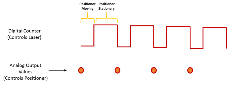
I have set the clock for my AO as the counter.
The analogue output should be raised whenever the Digital signal meter falls
SAMPLE_SIZE = 80
SAMPLING_RATE = 40 #Samples are written every 25 milliseconds
TIME = float ((SAMPLE_SIZE) / (SAMPLING_RATE))CREATE TASKS
CREATE CHANNELS OF AO
CONFIGURE THE TIMING CHANNELS
DAQmxCfgSampClkTiming (taskHandleAO, "PFI12", SAMPLING_RATE, DAQmx_Val_Falling, DAQmx_Val_FiniteSamps, SAMPLE_SIZE)CREATE TASKS
CREATE A CHAIN COUNTER
# Time high-low + time equals 25 milliseconds and is proportional to the frequency of sampling
DAQmxCreateCOPulseChanTime(taskHandleD,"DAQ/ctr0","",DAQmx_Val_Seconds,DAQmx_Val_Low,0.00,0.005,0.020)# The values of voltage DAQmx writing
DAQmxWriteAnalogF64(taskHandleAO,SAMPLE_SIZE,0,10.0,DAQmx_Val_GroupByChannel,Voltage,None,None)# DAQmx AO task start
DAQmxStartTask (taskHandleAO)# Counter DAQmx Start task
DAQmxStartTask (taskHandleD)#TIME is equal to the total time for the writing samples
DAQmxWaitUntilTaskDone (taskHandleD, 2 * TIMES)
I get an error every time that I run the task:
DAQError: Over Acquisition or generation has been stopped until the required number of samples were acquired or generated.

 function DAQmxStopTask
That's because my AO task is stopped for some reason any.
Is there an obvious problem with the code. Can it be structured differently?
best regards,
Ravi
I do all my programming in LabVIEW, so I'm pretty limited to help with programming syntax text. That being said, here's what I * think * I see:
Your AO task issues a call to DAQmxCfgSampClkTiming, but is not your task of counter. This probably leaves you with a meter spot which creates only a single impulse, which causes only a single AO D/A conversion. In LabVIEW when I need a pulse train, I would call a similar function of the synchronization with the clock mode is defined as 'implied '.
Hope this helps you get started, I don't know enough to give you the specific syntax in the text.
-Kevin P
Tags: NI Hardware
Similar Questions
-
Analog outputs with different time scales
I use products AO of a card PCI-6731 for an application scan head and I have some difficulties to achieve peak performance, that I need. I am contolling the map with nidaqmx drivers in c ++
Basically, an output controls scanning in the direction Y (which is a line of scanning and is very fast) and the other in the X (increment once per scan line, so much slower). The complication is that both exits start at an external trigger, because positioning is synchronized to a separate data acquisition card.
Now, what I do is:
-write the scanline for 0 output waveform
-set output 1 to a given position
-say next Trigger output card
-hangs at the end and stop tasks
What I really want to do, it is just tell him to start with on each external trigger output waveform of scanline 0 and output 1 increment to the next position. So I could do a complete 2D scanner with a minimum of control software.
Any ideas on how I could best achieve this? My understanding of the nidaqmx drivers I don't see an elegant way to do it.
I could potentially do some operations on the done callback, although it makes me a little nervous because the control PC running windows, it is not a real-time operating system.
Hmm I do not know exactly but there are a couple of things (it is close)...
The output frequency of meter in your example 5 MHz (20 MHz, 2 high ticks, weak 2 ticks), which is faster than holders 6731 for a sample clock. I thought that this would have given a material error... are you looking for errors once the task runs (for example using DAQmxIsTaskDone)?. There is a DAQmxCreateCOPulseChanFreq if you want to set the clock frequency directly (it will use the appropriate default internal time base).
The task of counter generates 1000 pulses per trigger, is what determines the number of samples generated by the trigger (I assume that you want it to be 1024 aka "numSamples").
The analog output task must either use:
(1) calendar continuous if the output will repeat indefinitely as several triggers are acquired.
(2) finishes pitch (N * numSamples) samples where N is the number of lines that you want to exit and numSamples is the number of samples per line. In this case, the task will end once the lines were triggered.
Best regards
-
I use the outgoing/incoming analog DDK with the DAQ 6341 SMU map.
The examples, for example aoex5, show a single timer (method outTimerHelper::loadUI), but the example shows the DMA loaded with same size of vector data.
There is a comment in the outTimerHelper:
 call rogramUpdateCount, which implies that memory sizes different pad per channel can be used.
(the comment is: switching between the sizes of the various buffers is not used)
Nobody knows what should be the format the DMA buffer for data from multiple channels with different frequencies?
For example, we want a0 with a sinusoid at 1 kHz and a1 with a sine wave of 1.5 Khz. What looks like the DMA buffer?
With the same frequency for each channel, the data are interleaved, for example (ao0 #0, ao1 #0; ao0 ao1 #1, #1,...), but when the frequencies for each channel is different, what the stamp looks like?
Hello Kenstern,
Data are always intertwined since each card has only a single timing for each subsystem engine.
To AO, you must specify the number of samples that will be released to the AO. You also specify the number of channels. Because he didn't is that a single engine timing for AO, each AO will be channel will be updated at the same time to update clock tick. Data will be interlaced exactly as shown in the example because each channel AO needs output at each tick of the clock to update. The data itself can change depending on the frequency you want to copy.
kenstern wrote:
For example, we want a0 with a sinusoid at 1 kHz and a1 with a sine wave of 1.5 Khz. What looks like the DMA buffer?
With the same frequency for each channel, the data are interleaved, for example (ao0 #0, ao1 #0; ao0 ao1 #1, #1,...), but when the frequencies for each channel is different, what the stamp looks like?
In your example, you must come with an update rate that works for the two waveforms (sine waves of 1 and 1.5 KHz). To get a good representation of a sine wave, you need to update more than 10 x faster than your fastest frequency... I would recommend x 100 if possible.
Update frequency: 150 KHz
Channels: 2
Then create you stamps that include complete cycles of each wave you want to produce based on the frequency of update. These buffers must also be of the same size.
Buffer 1: Contains data for the sine wave of 1 KHz, 300 points 2 cycles of sine wave
Buffer 2: Contains data for the sine wave of 1.5 KHz, 300 points, 3 cycles of sine wave
You can Interleave them as before. When the data are performed through the ADC, they are out different sine waves, even if the AO channels are updated at the same speed.
-
Generate analog output with the software "Timing" on 6009
I see that the 6009 does not support the synchronization of the internal clock. We need to generate an analogue waveform which changes very slowly, it performs a cycle every 10-20 minutes.
I saw an old post on the use of calendar software, but can not find a way to do this using SignalExpress.
Any ideas or references to examples of messages, etc. are greatly appreciated.
Analog output clocked by the software (DAQmx) in SignalExpress
I hope this helps.
-
How can I check if the counter entry is synchronized with the analog output?
Hello
I'm working on an application for counting photons. I use two channels of analog output on a PCI-6713 card to send a frame model to a set of XY scan mirrors. I then a photon count unit that emits a TTL signal when the photons are detected as a result of this raster analysis. I then use a surfboard USB-6211 to count the edges on this TTL signal.
I have problems that seem due to synchronization problems. I use the sample AO on the PCI-6713 card clock like the door of my meter on the map USB-6211. I use a trigger to start digital to analog output and a trigger of arms for the entrance to counter early. Is there a way to check that the analog output and counter entry of start of operations at the same time and are are synchronized? I basically want to monitor and compare the ao real sample of the PCI-6713 card clock door signal used by the jury of the USB-6211. I was able to export the sample AO clock and watch it on my oscilloscope, but not the signal from the door of the USB-6211.
Thanks for your help,
Brian
Update... It turns out that there is no problem of synchronization between my meter input and the analogue output. There was a difference of impedance when I connected my unit of counting photons to my USB-6211. This caused an error variable count rate. After accouting for this shift, the problem disappeared.
-
Analog output PCI-6251-DAQ-200016 memory overflow error
NI PCI - 6251 DAQmx, AIMD-752 motherboard, dual core processor, a lot of speed and the ram running WinXP Pro & LabWindows/CVI
get DAQ-200016 memory overflow error when I try to generate a signal of analog output with a rate higher than about 32 000 samples/second (?)
going on what? I have never seen it before. Is this a problem with the motherboard? "It's the same product on the CVI code example" \Cont Gen Volt Wfm - Int Clk\ContGen - IntClk.cws.
If someone has had this problem, and is there a solution?
Thank you
PS: full text of the message reads:
Measurements: On-board memory precision passing. Due to the limitations of system and/or the bandwidth of the bus, the driver could not write data to the device fast enough to track the rate of output of the device. Reduce your sampling rate, change the method of transfer of data (from interruptions on DMA), use a product with more on-board memory or reduce the number of programs that your computer runs simultaneously. Task name: _unnamedTask<1> Code of State:-200016
Well, I found my answer. For later use, Olivia NI Apps Engineering suggested I have change the mechanism of data transfer by this Knowledge Base document:
http://digital.NI.com/public.nsf/WebSearch/C326F7D33CA6DB0E86256DFE008043B7?OpenDocument
... so I inserted the line of code between the creation of the area of OCCUPANCY of the channels and set up the example of clock calendar.
DAQmxCreateAOVoltageChan( ...

DAQmxSetAODataXferMech(TaskHandle,chan,DAQmx_Val_Interrupts);

DAQmxCfgSampClkTiming(...
now, I am able to generate output to a 2.35 MS/sec... max sampling frequency not quite the 2.86MS / sec indicated in the specification 6251, but close enough that I'll stop complaining

-
Synchronization of analog and digital output with the external sample clock
Hello
First of all sorry for my English, I will try to explain what I want to do.
I want my PCIe-6321 to send two custom signals (modification sawtooths) on a mirror controller. I would also like to generate output with my card at the beginning of each tooth of saw. Everything must be synchronized with an external k-clock signal of 100 kHz. The idea is that whenever the PCI receives a trigger to external clock, it sends two analog output voltages and when he received 1024 clock ticks it will also send a pic of triggering TTL. What I do is first prepare the map and after that in a loop sending and modifing the output values of the two signals and at the same time send a digital signal Boolean in each arch, so when's done it 1024 iterations of the loop I send an event to the digital port. Attached you can see.
The problem is that I don't know how to synchronize both. Can I use the sample clock just to the analog output? I can use sample for the two outputs clock, or do I need to use the output of the meter? If don't know how to use it here.
If I do nothing else bad/wrong, I would be grateful for feedback.
Thanks in advance,
PabloI don't know how but I find the solution. I'm generating more than a positive value (as I was triggered maybe very fast the oscilloscope has been absent there). If I put the sample clock of digital output to use the sampling/ao/Dev1 clock that it doesn't, but if I put to use the same source as the OD (terminal where my external clock is connected), but the trigger to start the DO to be Dev1/ao/StartTrigger this works. I don't really know why, but it does.
Thank you for your patience and your help. I put here the final code.
-
Interleaving of samples: two outputs analog (tables with different lengths)
CHAN                   AOCHANNEL1       AOCHANNEL2       AOCHANNEL1           AOCHANNEL2       .. .and so on
SAMP                   * * * * *           *              * * * * *              *           .............and so on
Hi guys, how could I go on the interlacing of two arrays of different lengths in a two-channel analog output?
In the illustration above, for example, I like to write 5 values in channel 1, followed a string of unique value 2 and so on...
I use DAQmx library controls to achieve this (not LabView).
I am able to write unique values each time a task is opened without any problem, I was wondering if I can interleave the berries so that values are buffered and tasks are performed with greater haste.
best regards,
Ravi
target met: I've made the following changes:
CREATION OF TASK 1
CREATION ANALOG_VO channel 1 & channel 2 in TASK 1
CONFIG. CALENDAR OF TASK 1CREATED some TENSION with SAMPLES interleaved pre
WRITING TASK 1 VALUES
TASK 1 STARTED
DAQmxCfgSampClkTiming(taskHandle1,"",SAMPLING_RATE,DAQmx_Val_Rising,DAQmx_Val_FiniteSamps,2*SAMPLE_SIZE_WX) -
Generating analog output signals 4 with different frequencies
Hi all
I was trying to say to generate 4 different signals at different frequencies
1. first waveform is a sine wave with 5000 Hz,
2. other with 8000Hz,
3. third, one is a square with 25 Hz waveform and
4. fourth one with triangular waveform 50 Hz
all waveforms must be generated simultanoeusly.
I tried to generate with the task unique analog output and sample clock (clock rate is 100000). Cross in scope that I see only 5000 and 8000 Hz we generated correctly and the rest two waveforms show the incorrect frequency.
I guess that's due to the frequency of high clock to sample for more low frequencies for ex 25 Hz and 50 Hz. If I reduce the clock rate to get the lower frequencies properly so I can't generate frequencies higher correctly. (there's a clsh between frequencies and the clock frequency)
Is it possible to use DAQ board master sample clock and its magnitude downward revision (everywhere where it is necessary for each waveform separately) to generate all the signals at different frequencies at the same time in a single task?
-
Bad analog output help Every_N_Samples-NI-9263 cDAQ-9172 chassis (works with cDAQ-9178 chassis)
Hello
The NOR-9263 analog output voltage geberation works correctly with the cDAQ-9178 chassis but gives wrong result using the chassis NOR cDAQ-9172.
In the attached code example, a single cycle of a sine wave is composed of 40000 samples and came out in the background using Every_N_Samples at a rate of production of 5000 samples per second.
The output buffer size is set to 10000 samples.
Prepare us the buffer writing 10000 samples 1, then write the remaining data in the background using the Every_N_Samples callback.
Bug: Using the cDAQ-9172 chassis, to the 5000 s/s sampling rate with the help of an external field (or through closure to another HAVE), we observed that 1 10000 samples came out twice, followed by the rest of the waveform. The last 10000 samples are never exits. If you are working properly, we would expect to see 1 full cycle of a sine wave.The bug does not occur with the chassis NOR cDAQ-9178. I use the driver NIDAQmx v9.2.1f0 on Windows XP
The bug does not happen with simulation devices, so you will need to use harwdare real to reproduce.Please find attached an example of code C based on the example program OR "ContGen - IntClk.c" to reproduce this bug.
Thank you
whemdan,
The MathWorks
Hi whemdan,
By default, DAQmx regenerate old samples if no new data is available. To give the correct behavior, you can:
Use DAQmxSetWriteRegenMode to disable the regeneration (DAQmx_Val_DoNotAllowRegen). In most cases, this is recommended if new data are written continuously in the buffer as the build is in progress.
If you just need to generate 40 k samples, you can write them just all at once, rather than in 10 pieces of k (the code you attached probably is just an example, so I'll assume that you have a reason to write the data into segments in your actual code).
I think the difference in behavior between 9172 and 9178 can if explained by the different way, buffering is set up on each product. The 9172 uses a buffer of 8 k (on the STC2) in all cases (source). The 9178 uses an 8 k of memory buffer (on the STC3) If you use regeneration shipped, but uses the 127 samples FIFO cartridge, if you use no on-board regeneration (source).
Then... on the 9172 8191 samples are immediately transferred to the FIFO. By default, the hardware is going to request new data when the FIFO is less to fill (this is configurable with DAQmxSetAODataXferReqCond). I'm not sure what the transfer data request size is in your case (you can set the maximum value with DAQmxSetAOUsbXferReqSize), but obviously it is bigger than the other 1809 samples that you have not yet sent to the Board of Directors of your first entry. At this point, the pilot will regenerate 10 existing k samples so that sufficient data will be available to meet the demand of data transfer.
The 9178 however use the FIFO of 127 smaller samples so you will not have the same behavior in your case.
In summary, the behavior is explainable by the difference of material. If you want to avoid to regenerate old samples, you should ban the regeneration using DAQmxSetWriteRegenMode.
Best regards
-
DAQ product with +/-analog output 12V?
We are looking to update a manual test area.
We are looking for a product DAQ with analog outputs capable of +/-12V
We are not generating waveforms. Just using LabVIEW to a tension he set in the range of - 12V and + 12V.
OR anything with this ability he selling?
I found the NI PCI-6703 and would serve our needs except that it is +/-10V.
Good morning New York,
Consider the SMU-4322 or NI 9269. The SMU-4322 supports + / 16V by channel. The NI 9269 has 4 (+/-10V) channels that can be cascaded for isolated older tensions.
Kind regards
Izzy O.
Product Support Engineer
NI.com/support
-
Strange problem with analog output PCI 6251 and BNC-2110
I'm controlling current source of third parties using the connectors of analog output on my card PCI 6251 and BNC-2110.
The current source needs an input signal of 0.1V. I tested it using a battery, the potentiometer and the voltmeter, and by manually adjusting the voltage of power current works - current output with control voltage scales according to the specifications and is relatively stable.
The data acquisition card works too - when I connect a voltmeter to the AO0 AO1, the measured voltage corresponds to the target with great precision value.
But when I connect the current source of third AO0 AO1 data acquisition card, the measured output voltage drops and fluctuates. This applies to both channels of the AO.
I wonder what is the problem here. I suspect it could be a matter of the grounding - the current analog control of the source is an entry with two floating terminals differential. I tried to return the switches FS/GS on the BNC-2110, but that makes no difference.
Anyone knows similar behavior? Does anyone have any suggestions?
-
Is a PCI-6120 card in a computer with linux useful for the analog output?
We have a PCI-6120, and we want to use in a computer with linux OS, to the analog inputs and analog outputs. I have downloaded the driver NOR-DAQmx Base 3.2 for linux, and in the file README.txt only analog input is mentioned for this Council. It is possible to use this card PCI-6120 in linux, with output and analog input computer?
Best regards
Hey, Gallas,.
This line in the README file simply refers to the PCI-6120 by its more popular, analog input subsystem (given that it is a simultaneous sampling device, the AI is the most commonly used subsystem). But NEITHER-DAQmx for Linux does not have the same limitations NOR-DAQmx base has. In other words, it supports the ability of analog output on the PCI-6120.
Kind regards
Sam
-
analog inputs with outputs analog delayed
Is there a straightforward way to configure Labview as a generator of analog delay? I need to generate an analog output that is identical to, but delayed, an analog input signal. The delay could be quite long, on the order of a second or two. I'm using Labview v8.6 and I have a card PCI-6251. Any help would be greatly appreciated.
Kind regards
Stephen
Hi UKslj,
I went ahead and took a stab at it - how does this look:
Use delayed output Version of avian influenza in DAQmx AO
The downside is that you need to set delay high enough so that the task of the AO is not negative, but I think it should be more or less what you need to do. Let me know how it goes!
-John
-
Recommendations for hardware OR with a minimum 6-channel analog output
Hello world.
Currently I have the NOR-device, USB-6009. However, it offers only up to 2 analog output channels. I'll need to have at least 6 channels of analog output. Therefore, can anyone recommend me any device OR that matches my needs (preference is the USB series)?
Kind regards
Jonathan
Did you go to the page data acquisition . You can use the different selection tools to narrow down your choices. Given that you have provided only a single parameter (number of channels), it is difficult to recommend anything. Determine what else you need (sample rate, voltage range, etc.) and you can call your sales engineer OR local and get all the help you need.
Maybe you are looking for
-
Satellite C650 - 179 Win 7 - speed LAN from the NAS stand out very well
Hello LAN-speed and to my NAS (inside my network) differ extremely well. Upload is extremely slow, about 24 KB/sec. I tried following: -using another computer (also Windows 7 but a HP) connected to the same Ethernet cable (and the same output of the
-
I just bought the new iphone 6s on Black Friday and tonight I could not slide to unlock. I tried to turn off phone however, it wouldn't work. Tried to use Siri, but he randomly calls people, facetime etc... I have not updated my phone since the purch
-
Hello How to combine or merge the table 1 d of digital waveforms with a simple digital waveform. As givien in the attached VI, I want to display the datalines chart & graph of control lines in a simple graph of digital waveforms. Thanks in advance
-
4 reviews in our family. The admin password changed or misspellings and now cannot get under the admin user. Please, advice. Delete or refurbished. Thank you.
-
Display on the HP Envy 15-j040er
What is the display is HP Envy 15 - j040er, connector, and other important features? Is a replacement for another great display quality?Really need your help.