Analog pulse of a photon multiplier tube
Hello
I am trying to establish if it is possible to count random negative analog impulses of a tube of multiplier of photon (PMT) with multifunction data acquisition OR or boards of counters/timers?
First of all, the properties of the PMT output are as follows (single photon response):
- 1.5 ns FWHM
- -50 mV to 400mv (random because of the amplification process in the PMT)
- Up to 5 million pulses per second (higher cause the overload sensor) who arrive at random times.
I would like to do is make the counting of simple events or events buffered count.
All counters seem to only be able to count digital TTL pulses. In this case, I have some electronics in mind which will convert the pulse the pulse of positive 5V CMOS logic (which, according to this site, is suitable for counter inputs) external signal conditioning. It also contains a dicriminator circuit to ignore the pulse below a threshold. With this signal, I intend to send to a meter entry NI USB Multifunction DAQ BNC for counting of events event / buffered.
However, in the hope to reduce the cost of my system, I was hoping it could be a way to define an analog trigger to create a pulse TTL of one of the of cards OR, therefore quite dodge the need for external signal conditioning?
Any help would be welcome.
Kind regards
Sean
You may need to strech the pulse to meet the minimum of the input of the meter.
I know you want to do without extra signal conditioning... However, we are building a signalconditioner to our task with a comparator MAX961ESA provided... 5V-driven layout is in the technical sheet
As a simple pulse strecher, I would try a simple low-pass RC before the entry comparer.
Tags: NI Hardware
Similar Questions
-
Detection of pulse NI 6259 photon counter min
Hello
I have a PCI 6259 DAQ card which I use as a counter. Is there a limit to the minimum pulse width it can count all operating as a counter? My meter of photons gives the TTL pulses with widths of 50ns which I think is less than what the meter may read unless I'm mistaken. I use 100 kHz as the clock source internal clock. Is there anyway to get the counter to pick up these small impulses?
The NI PCI 6120 DAQ card would be a better choice for this kind of measure? I should be able to get my hands on a bit of time.
Thanks for your time,
Select this option.
Well I just learn something new, I didn't realize earlier that the time base of 100 kHz could serve directly as a sample clock for the tasks of counter as described here.
The task of the meter must be able to count incoming edges at rates well in a few tens of MHz. If you stop the recording of managers when your fn Generator hits 1.5 MHz, I bet it's because the impulses become too round or too low in amplitude to be recognized as transitions TTL.
Try to insert a property node DAQmx channel between the creation of the task and start. Select the property "Counter Input-> edges of the County-> input terminal". Make a writable property and create a constant connection. Right-click the constant, select "Browse...". "and choose the 20 MHz or 80 MHz time base. Run it and check that you get always 200 or 800 counts per interval.
If using the internal time base works as expected, you will need to put emphasis on the integrity of the pulse of your fn generator and your real instrument.
-Kevin P
-
Hallo,
I use the following system:
- OR PXI-1044 with controller NI PXI-8109
- OR PXI-2564 switch module to turn on the monitor of my test device
- Data acquisition multifunction NI PXI-6259 to measure the signal that responded to the questionnaire jump
The two cards are the same - PXI trigger bus. For both, PXI-2564 and PXI-6259 I use DAQmx to set the reading and writing of the channels.
Now, I want to measure the time between the digital output, my unit turns and the analog input, which measures the response of my system.
I can't do work by myself, please help me!
I thank Ludwig.
Hi Ludwig,.
If you can't give us any VI we have difficulties with to help you.
Because I Donat knowledge how your program is mounted it is not easy to know where you should enter signals.
Here's a question similar to yours:
http://forums.NI.com/T5/LabVIEW/best-way-to-measure-time/TD-p/178704
and 2 external links:
http://www.ehow.com/how_8698983_measure-time-LabVIEW.html
http://objectmix.com/LabVIEW/385152-how-can-i-use-LabVIEW-measure-time-between-analog-pulses.html
-
NEITHER 6052e: can I re - route the analog output of DAQ for PFI?
Hello
Does anyone know if it is possible to route analog output to one of the PFI (e.g. PFI0)? I use NEITHER 6052e and I would do the following: 1) output a signal to DAQ0; 2) then a few hundred milliseconds a signal of DAQ1; and then 3) read out a simple analog pulse on any output connector external to trigger an external device.
Thank you very much for your help!
Hello sometimes.
Could you please provide more information about your hardware configuration:
What devices are DAQ0 and DAQ1?
Are you using a PXI and PCI 6052?
When you say AO reroute to PFI do you mean you're trying to wire AO into a PFI line for release purposes or are you trying to exit and the analog signal of a PFI line?
-
Rate for the low number of County Digital events
Hello
I'm trying to use the example of digital counting examples DAQmx Events.vi to count the pulses of a photon counter. As long as the light level is high enough, it works very well. But, when the light level is below a threshold, no count is read. I checked that's not because of the photon counter by testing with an independent instrument.
It seems like it might have something to do with the rate at which counted events are unloaded (PCIe-6321) hardware in the computer, that is, there is a minimum threshold of count indictment before such a transfer of data occurs. I'm voting for the number of levels of every 100ms.
Any help would be appreciated.
Thank you
Alex
-
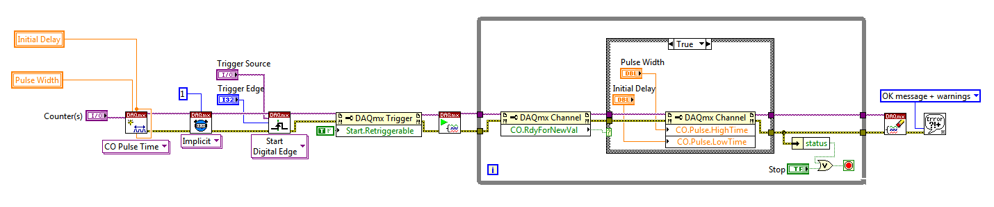
Hello
I use a mx-acquisition of data (NI USB-6211) and I would like to use it to generate a pulse of digital modulation
that is triggered by an analog input signal. The input signal is a pulse of squares analog modulated
What is almost periodic. It's because of my set up, and I can't do anything with it. I would use the
before the edge of this signal to trigger the production of a digital pulse signal modulated (0-5 V). My
problem is summarized in the figure given in the annex. I would also like to have the possibility of
Configure the 'backwardness' and the term of "TAU_LED", while the VI works.
I have looked at several examples of instrument OR meter generation, generation of PCI I / AO, but doesn't
not managed to solve my problem. Does anyone have an idea of how start with my problem? Are there
No matter what example VI that I could start to change?
Thanks in advance,
Gregory
Hi Gregory,
Sorry I forgot to mention: the Initial delay applies only to the first impulse of a redeclenchables generation. Every subsequent impulse will use low time as the Initial delay. I agree the behavior is not very intuitive (our latest guidance of series X actually supported an Initial period to allow on property Retrigger), but it is described in this knowledge baseand should also be mentioned in the DAQmx help.
As you generate just a single pulse, I would recommend simply connecting the Initial delay and at the entrances of low time to the same value for each pulse will be delayed further.
Exit tasks ongoing counter currently supports DAQmx writing. However, the finished generations or simple impulse are not. However, you should always be able to get the behavior you need with a property node DAQmx. The current solution on the series E/M is:
Again, this is not the most intuitive, but I checked that it works on my 6210. After writing a new value in the software the pulse will be updated on the 2nd trigger. Attached is the code stored in LV8.2.
Best regards
-
trying to trigger multiple analog measures with each pulse of an encoder 500PPR
I'm taking steps analog multiple sensors to formula 6 with each pulse of a 500 ppr encoder and write these to a file. I met problem is I don't get 500 readings with 1 revolution of the encoder the more I received is 187 but is not consistent.
using
Card series E 6024
EIB L25G encoder
Still relatively new to labview as well as using an old version 7.0
Thanks in advance
Never mind after watching it somemore I found that I was using the wrong sampling frequency
-
How about using labview vi of the filter and multiply vi to replace the analog filter and amplifier
Hi all
I use a data acquisition system to acquire a weak signal, it seems to a voltage amplifier and low-pass filter before the acquisition of data. I was wondering, if I use low-pass of the labview vi of the filter and multiply vi to process the signal picked up by DAQ, can I get the same effect as the analog low-pass filter and amp?
Thank you!
No!
1. any system of sampled data must be band including prior to sampling in order to avoid aliasing. It is impossible to remove aliasing after collection.
2. the resolution of the DAQ system will be so low that you'll very 'fat' scanning and you will lose a large part of the information in your signal.
Sorry, but you need to amplify and filter in the material before the data acquisition device for best results.
Lynn
-
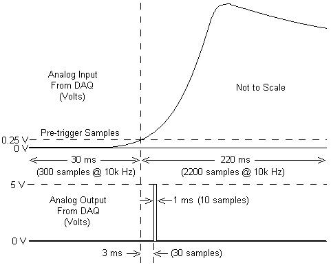
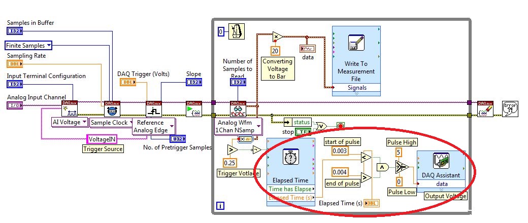
I am working with a combustion chamber and using a system of data acquisition (with the hardware OR SCB - 68) to read the pressure in the cylinder (such as analog voltage). I'm trying a pulse delayed, 1 millisecond to 5 volts of output once the pressure in the cylinder is high above 5 bar (which corresponds to an analogue voltage of 0.25 V). I would also like to record 30 ms samples before the trigger and 220 ms samples after the outbreak. The following image shows visually what I'm talking about.
I created a LabVIEW VI (which is attached), but I keep running into 2 issues:
- When I run with samples finished after a period of time, I get error-200281which I don't quite understand.
- Using the Express VI 'Out of time' to keep time for the pulse I can not get a resolution of 1 millisecond, the pulse is not generated when I put the window between 0.003 and 0.004 seconds for high pulse (i.e. the resolution of 'Elapsed Time' seems to be too coarse).
I'm a beginner to LabVIEW sorry if my questions are trivial or my VI makes no sense, but I was stuck on this during more than a week. Any help would be greatly appreciated!
Thank you
Morgen
This isn't a good way to trigger a pulse.
Use a trigger DAQmx to send the pulse when your acquired signal exceeds 250 mV you specified.See this for DAQmx trigger:
-
Acquire analog data entry triggered by the great time and low time of a pulse meter
Hi all
I'm writing a VI in labview 8.1 version to test the sensors. The power supply of the sensor is pulsed and I need to get a value when turned on the power of the sensor and the power of the sensor is turned OFF (measure Max voltage when the current flows through the circuit and voltage min when no current flows through). My cycle is like ON 2 seconds for 8 seconds.
And I want to acquire a reading in each of those States permanently. I am able to use a pulse meter to make the pulse but how can I tie this with the recording of data, then you can be sure that I log into a data point in the State ONE and the other to the OFF state?
Thank you
SJ
Acquire the pulses of the meter on a different path to analog input. When it is high your sensor is activated.
Lynn
-
conversion of pulse analogously in Digital pulse sequence
Hello
I work to detect the peaks in a particular time interval say 'x '. I acquired the analog signals (impulses), as shown in the image here AcquiredPulse of analog card with data acquisition. Before detect the peaks of the pulses of different amplitudes having almost the same period of time indicated in the picture above, I want to convert them in digital or of the same amplitude pulses pulses , so it won't be easy for the detection of peaks process. And after getting what I need to know the time interval between pulses.
Can someone help me with the implementation of the present.
By this Vi, you can convert the waveform
-
How to send a pulse only to analog output
I send a function rect through to the ao, thorugh the transmitter transducer, then a receiving transducer through AI. Although I'm kind of a signal, I can see that there is something wrong. What I think is happening, is that the pulse is transmitted continuously while I want it to be sent once. of the received signal, waiting for the signal to reach 0.2/1500 s as the medium is 0.2 m in diameter and the speed of the sound probagation through it is around 1500 m/s. So, with these considerations, I have the following questions:
1. How can I configure the wizard daq output to send only 1 rect function
2. read permanently or for a period of time
I have attached the output and input along with a photo of my VI signals
Thank you
Hi Macane,
For a unique configuration of generation/acquisition, you would set your DAQ Assistant to finish instead of continuous and calculate how many samples is your only impulse you send. For the acquisition, you can configure a finite acquisition of trigger reference analog where it will begin to capture after your signal is received, or if you do not want a triggered acquisition, you can set the number of samples to acquire. For example, finished task sampled at 1 kHz to 2000 samples would correspond to a second acquisition 2.
You can configure all the wizards within the express VI data acquisition by double-clicking the VI. I hope all goes well!
-
9174 triggered output pulses and analog input synchronization
Hello
I have a cDAQ 9174 with a 9215 analog and a 9401 module. I wonder if this configuration is suitable for my use: a trigger digital extern is sent to the system to trigger a task of analog input, trigger a generation of pulses, with another counter, count of trigger events. Using two counters on 9401, it seems I have no left Terminal at the entrance of my trigger signal. The trigger DAQmx vi does not show counters entries in the list of signals; and if I select a PFI line, an error that says that the line is already in use..., I missed a few obvious solution? I have change my 9401 to a 9402 did?
Thanks for any help,
Vincent
Hi Vincent,.
So, looks like you need a single line to use as input to trigger events and another line to use for a generation of pulse output. This should indeed be possible, since the 9401 has 8 lines that are configurable nibble (i.e. lines 0:3 could be configured as inputs, while the 4:7 lines could be taken out, or vice versa).
However, a big caveat with the 9401 is that the lines must be reserved before each task is started. This is a limitation of the direction of the line is implemented in hardware and is common as customers when something they using the 9401. Explicitly reserving your tasks before starting must correct the behavior if that is indeed what you see.
Best regards
-
How can I use my PXI-6115 meter analog signal trigger to generate pulses of frequency
I work on a PXI-6115 DAQ card and want to using the analog signal to trigger the counter it's generating frequency pulses. The manual says the analog trigger is supported, but I can't use an analog signal to trigger the start of work, in the test, I use the counter 0 to generate pulses and use the signal input port analog trigger PFI 0, can someone tell me what it is? My test VI. & error message appears in the attachment.
Best regards
If you read the error you can see digital triggers are the available trigger only when you use the output of the counter.
You can work around this by setting up a dummy analog input task which will trigger an internal digital triggering when he sees the right analog trigger.
See this thread for more details:
-
How to build square 3 ph pulses and use them to trigger the two analog inputs.
Task:
1) generate continuous 1 Hz ms 45 pulses on three lines of output offset 120 degrees.
Other neighborhoods, three phases (three outputs) 120 degrees out, but instead of sine wave should be a volt 5ms 45 along with a second ground pulse. I need these impulses to control an external circuit. The tolerance of 1 Hz is loose, but 45 ms must be at 100 us.
(2) measure (trigger) two independent DC voltage over 45 ms 50 ms after each front (leader) amount of each pulse. 45 to 50 ms must be 100 us.
Other neighborhoods, begins each measure 45 ms for the DC source #1 and 50 ms for the source DC #2 after opening (rising edge) of each pulse for total of six measurements per second 1 (by 1 Hz cycle).
(3) an analog output must provide ongoing (to be booked) negative DC voltage to be used as a source of supply for external circuits.
I timely when I can generate the 45 Hz by using CO (0) 1 ms pulses continuously and the trigger I (0) on falling edge. I (0) is hard wired to triggering I (0).
How I do HAVE another (1) and two other lines (two phases) and link them to HAVE (0) and HAVE (1)?
Equipment: LabView 8.6.2, PCI-6221 (37-pin)
Hi behappy.
Thanks for posting and welcome to the forums EITHER! I think we can get what you need with the variety of the 6221 37 pins:
(1) our machines of the M series have 2 counters, so you cannot generate all the impulses of 3 of these alone. A solution would be to use outputs digital correlated.
Unfortunately, the 37 pins 6221 has only two IO digital correlated, so you should use a strange mixture of digital meters and IO to implement three impulses. It would still be feasible - for example, you might use a counter for a time base for the digital i/o lines and the other counter to the third output pulse. You would have to match the beginning of the two counters to ensure the phase of your signals.
2) there are essentially two parts to this question, so I'll try to split:
(i) combine the three impulses together to generate a single sample signal out of. I think this would be doable on a different set of M with a higher number of digital I/o lines correlated using change detection (see the user manual of M series). However, at this stage, we are just out of digital lines correlated to use, and I don't think that's possible on the 37 pins 6221.
If you use the 6221 37-pin, which you will probably need to do is to provide your own external circuits OR three pulses together.
(II) get the 5 ms delay to enjoy your second channel. Since you have already discovered that you can sample the falling edge of the digital signal for the delay of 45 ms, you would just add another delay of 5 ms before taste you your second I. You should be able to do this by setting the clock to convert DAQmx frequency (5ms corresponds to 200 Hz). The clock to convert, it's what actually sampling data (keep in mind that the boards of the M series are multiplexed).
To do this, simply use the property calendar DAQmx node, then select: more > converted > rate.
(3) this one is easy - we have not yet used all channels of AO.
So the 37 pins 6221 is a little less ideal because you have not enough correlated digital i/o to make the generation of pulses or change detection - but he has yet to do the job if you can combine the three impulses yourself outdoors and don't mind not using the additional counter to generate the third impulse.
I hope this helps, if you need any help to find relevant examples, please do not hesitate to post in return. Thank you!
-John
Maybe you are looking for
-
HI -. I'm trying to convert a string to scientific notation in doubles. First of all, I use a conversion of "line number" then a conversion 'duplicate '. When I probe the values my string is "+ 050.00E - 03" but the number is "50." I still have to ad
-
I noticed sometimes the server Vsphere my guests and my 7.1.1. vRanger of connection depends on the will go down. The reports that I have vRanger connection send me every day won't NOTICE and either give me 'nothing' in the past days or worse state
-
m476dw not wake - coil/queuing
Only had this printer a week and he made my nut. Running windows 8.1 on all our PCs in the company doesn't seem to be able to get an any of them to print our new M476dw have updated the firmware to the last 20140605. V.difficult to print, if I run
-
I would change my function keys on my Vizio slim and light touch MODEL NUMBER: CT14T-B1. The function keys used to control my screen brightness and volume. Now, I have to hold down the FN key first, then select the appropriate function key. Can some
-
How can I view author and time of a cell (not the annotation) comment in FRS?
I have report FRS in which one of the columns displays the comments entered for the data cells of planning. With the help of CelText() I can show the comments themselves, but not the author and Date (which are visible when you select comments in the