Analog readings DAQ with cDAQ9179
I am using a cDAQ-9179 with NI 9205 AI cards in slots 1-10. Card 1 is connected to the signals from DUT 1, 2 card is wired to report of DUT 2 and so on. When I put in place a task (differential) analog input with channel 1 HERE of some of the cards (cDAQ1Mod3/ai3, cDAQ1Mod5/ai3, cDAQ1Mod1/ai3, cDAQ1Mod7/ai3, cDAQ1Mod9/ai3), set up the synchronization to a sample clock (rate: 44100 Hz, number of samples: 4410, sample mode: finishes) and then start and read (number of samples: 4410, multi-channel, multi-sample, 1 d waveform analog), I get a timeout on reading error saying "some or all of the requested samples are not yet acquired".
If I use the same code to read from 2 channels of each card, I get no error timeout on reading.
If I read 1 signal or 10 signals of each card, I expect to be able to read the amount of samples that I specified in the node timing. Changing the time on reading VI-1 (indeterminate) does not solve the problem.
Does anyone have an idea about what is happening here?
I pointed at certain sections of the Knowledge Base through support OR which lead to the solution. There is a bug with DAQmx 15.1.1 and cDAQ-9179 chassis that I use.
http://digital.NI.com/public.nsf/WebSearch/B968369CBE7C71CE86257FC6005664F2?OpenDocument
http://digital.NI.com/public.nsf/WebSearch/444177578E314BBE86257FD20070C377
An update to 15.5 DAQmx solved the problem.
Tags: NI Software
Similar Questions
-
NEITHER USB-6501-24-line digital i/o (OR-DAQ) with LabWindows/CVI 7.0?
Hello
Can I use a recent NI USB-6501-24-line e/s digital (OR-DAQ) with LabWindows/CVI 7.0, although Labwindows/CVI 8.x is required?
Thank you
Dayne
Hello.
In DAQmx Readme, you can see which version of the CVI are supported by the version of current DAQmx. For a map of 6501, 8.7.2 or DAQmx 8.9.5 versions work.
Concerning
-
Can I synchronize list XCP DAQ with my analog input data data?
Hi all
"I use ' ECU M & C" for measurement of a computer data using the XCP DAQ list. "The data is read at the sampling frequency I put in ' MC DAQ initialize.vi. This works well.
I want to associate this data with my DAQmx device measures. Is it possible to synchronize the clocks of the sample (by RTSI?) in the same way, it would be with DAQmx CAN synchronize data?
Material: NO PCI-CAN/2 & OR PCI-6229.
Thanks for any input.
PJ
Hi PJ,.
Well, I think I understand now, I don't know why I DINA see this before. It is not possbile to do this with the ECU Measurement and Calibration Toolkit, sort of XCP DAQ, is not something that you are able to do.
Best regards
-
Problem with MX DAQ with USB-6009
Hey guys, I'd be happy if someone of you can help me!
I want to measure the tension of a place and it was working fine, but now I want to measure the temperature of the room too... and that's my problem.
When I put 2 virtual channels DAQ, that it won't work, I get an error when I tried to read the voltage and the temperature.
Error-50103 occurred at DAQmx Read (analog 1-d Wfm NChan NSamp) .vi:1
Possible reasons:
The specified resource is reserved. The operation could not be performed as indicated.
Task name: _unnamedTask<17C>
If I click on continue, I get the same error again and again and again...
Can someone help me on this?
How can I track more than one thing with DAQ MX?
Because when the measures only one thing it works, but when I try 2 or more, it's crushing.
I download the vi and an image with the code!
Thank you
You should do something like that. I don't really know if the data is sorted by the column or lines when you return a 2D array. This is for temporary data in the last column. If it is sorted by lines, then wire the '7' in the line of the array Index. Or, move the table to Index at before the transposition table.
You can use the function remove the table to remove temp data before moving on to the loop for. It is up to you. The for loop you have is built also hurt. Make use of the functionality of an Auto-Index loop and you don't need over to Terminal n of the loop and eliminates the Index table inside the loop function for.
Spend some time and take the LabVIEW tutorials and look at examples of delivery to get an idea of how do the work of loops and options for indexing tables.
-
To write a waveform to two outputs analog of DAQ(USB-6215)
Hello
I use USB-6215, who has two analog outputs and having to send the same waveform through the analog outputs two of my DAQ. at the same time. in fact, I have a text file consisting of a code word (please see the attatchment) with dt, freq and annex 0 in the first column and other columns contain the word coded. Withe the help of dt, the rate and the data I did a waveform with the wave of construction VI. I am able to write this wavefrom through an analog output A01 right now. I want to know how I could write the same analog waveform other AO0 out simultaneously. I use a source of external triggering via PFI0 to be triggered. for now, I use the write.vi DAQmx (analog channel 1 DBL 1 d N samples) and DAQmx create virtual channel.vi with dev1/ao1 as the physical channel. For more information, I am attatching the program along with the text file. Please see page 2 of my structure of matter in the VI attatched.
Thank you.
Kind regards
Raja
Hi Steve,.
his works now. I changed the instance of writing DAQmx for analog waveform samples N channel N. still, I now that a single waveform. How could I do like two like it (writing DAQmx) will not accept a single waveform as the entry as the number of channels in the task will now be 2 where, under the waveform has an exit.
Kind regards
Raja
-
Analog value read with DSC Module Modbus
Hi, I have a Delta PLC with an AD converter module. I use the four analog channels and in one of them, I have a thermocouple which displays temperature data on a microprocessor thermocouple meter. However, I want to display the data in Labview. The controller communicates with labview through the DSC Module of labview with success, but I am not able to read the data. Looking forward to your help.
Found the solution. addressing to the modbus master was different for this model of plc, so I looked up the address for delta plc Modbus and the analog read list has been a success on labview.
-
In the test, I'm trying to Setup, I need to record readings of load with the subscribed initial charge. I take the initial read and who then subtract all of the following readings. I have a pre-load of 50 lbs, I want all surveys carried out during the test to compensate in 50 lbs.
Currently, I take a reading before entering the loop of the acquisition and subtract the initial read of all new readings before saving the data. What I want to do, it's somehow say DAQmx to shift for me. Is this possible? and if yes how forge I who?
Thank you
Hi Ryan,
You can use the following function:
Int32 DAQmxCreateLinScale (const char name [], slope float64, float64, int32 preScaledUnits, const char scaledUnits [] yIntercept)
If you create a scale in the above path, you must change your CreateAI... According to Chan. Change the setting to 'units' to 'DAQmx_Val_FromCustomScale' and 'customScaleName' the name value that you specify in the DAQmxCreateLinScale function.
You can find detailed information in the help of the Driver nor-daqmx c reference!
Welcome,
-George-
-
Calendar in a loop DAQ with write, read, then a bit of transformation
(I use a PXI-6052e, DAQmx and Labview 8.6. I have time real module installed if it would help to solve the problem that I have.)
I am writing a control program that requires a certain sequence in a loop, which is:
1 four of the digital i/o pins on the Board (to set the status of a switch), then update
2. to provide a boost to a brooch (to launch the failover), then
3. take a sample on each of the three analog inputs,
4. processing on these three samples and use the output to update maps.
Now, I know that, separately, my methods of control for the switch and the subsections of sampling/dsp doesn't work. However, when I try to combine them into the same loop there is a problem with the sync the sequence above. Clearly I'm not going to things the correct way.
I have attached the main VI containing the 'main measure loop' so that you can see how I'm trying to do things. The loop is in the last picture of the stacked sequence (the first two are just stuff of calibration - ignore them).
Ideally what I want is to have this loop running at 1 kHz (for example), and each iteration has the above followed by sequence [i] in that order [/ i]. To monitor the output pins and switch output but it is clear that this is not the case.
Thank you very much for any advice. I know that I'm doing it wrong, but I can't work on how it is supposed to be. I tried using a loop timed but in vain.
I've implemented the attached file. If you could have a look to make sure that's not crazy, it would be great.
I use two counters. The first is at 1 kHz and begins immediately. The 500 Hz counter is triggered to start on the front of the meter to 1 kHz.
Also, AI samples are acquired on each rising edge of the counter from 1 kHz.
In the future, I should be able to increase this to have a few more counters, I suppose?
-
Communication problem 6210 hardware DAQ with DAQmx 9.2.3 (Err 88302)
I would use NEITHER-USB-6210 with DIAdem 11.1 under Win 7 Home Premium. DAQmx software and supplied drivers are version 8.6, but does not support this DIAdem 11.1 (DAC-NOR-DAQ interface did not show any existing signal). So I decided to update software DAQmx on latest version 9.2.3 which should solve this problem. After installation, all previous configuration items, MAX moved well and DIAdem DAC block indicated all signals with success but start of acquisition and measurement is impossible since. After firmwareloader establishes the material connection seems to be running, but any attempt to transfer data or start any function Max raises failurie event-88302 "an internal error has occurred." Anyone help me please?
Dear Mr. Varga,
After that the PC was clean from previous installed everywhere DAQ and new installation repeated once more, problem has been resolved and now the system is fully capable to work with DIAdem, as well as with the Net. request.
Kind regards
Milos Riha
-
Slow assisatnt DAQ with events
I have a question on the DAQ assistant. I'm currently programming an application automation at least 8 simultenously FOR loops and I use 3 different converters AD / DA. My problem is that when I'm working with the DAQ assistant nor (NI USB 6229) in this program and I communicate between the loops using son of the event (structure), the loop where are elements of DAQ assistant really slowing down. I mean I cycle every 3 seconds, this one is really kill me because everything else is really fast enough and only this one is slow (other two converters AD / DA are ok, they are not OR). Have you any idea where can be a problem and what to do to speed up my request?
Sounds like a race condition, your local variables read an old value, which causes a loop to stop that you start the program. If you use local variables to stop several loops, it is very important to ensure that they are properly initialized at the beginning of the program.
/Y
-
How to read 3 analog inputs simultaneously with 6070E?
Hello
I wanted to read 3 analog signals simultaneously using cards of acquiring data NI PXI-6070E and Labview 2010.
I can with success read and record the 1 signal (which you can see in the attachment), but do not know and can not find examples on how to read 3 signals simultaneously. Any help, especially a simple example would be great.
Thank you!
Just click on = pull down from the constant physical channel, select Browse and shift-click or Ctl-click here to add other channels. You can also type in new channels with the ai0 syntax: 2 for three continuous channels for example.
-
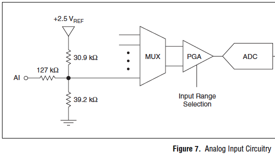
We currently have a 9205 analog input module. I have several analog inputs (CSR) receive signals output of material. Recently, I discovered that if a piece of equipment is taken offline, creating an undefined signal for the data acquisition module, other chains are made and show wrong values. If I run the open path, channel signal wire to a ground, without the presence of blood, that the display returns to normal operation.
I thought about installing a switch, one side of the switch would be in line with the positive wire, connect the other end of the switch through a resistance (emptying) of the common GND on the module. Is it possible to use the labview environment to solve this problem without component externally?
What you see, it's fairly common in the multiplexed A/D converters. The ability to entrance of the accusations disconnected channels to some (unpredictable in general) and this tension can create the effects you report. The only real solution is to connect all entries not used to a low impedance source in their common mode input domain. Often a short to ground is the best thing to do. I don't know of any internal option to achieve this.
Lynn
-
Timed by analog material out with PXI-6733
Hello
I'm a little confused on the possibilities for the material of analog timing of release of a PXI-6733, using pulses of DIO to a separate device.
I want to generate an analog voltage on the signal for synchronization from another device.
Lets say I want to generate tensions: 0, 1.3, 8, 0 volt. Sometimes 1 US, 402 U.S., 1004 US, US 1503. (we = micro seconds). I DIO card that will generate TTL pulses in these moments there and let's say I have the latter on a trigger PXI, PFI line line or enter the map of 6733.
How to configure DAQmx with labview to perform this task?
Thank you
Paul.
Hi Paul,.
There are many ways we could do this. The first thing that comes to mind is to sample AO clock battery LIFE of your device. All you have to do is do an array of doubles with the values that you want to scroll through and then then whenever you get a clock pulse we will update the output. You can see examples in LabVIEW by going to help > find examples. "" "The NOR example Finder will appear, and you can find many useful programs in input and output material" DAQmx "analog generation ' record of tension. To achieve my method, I opened the Gen Cont tension Wfm - Ext Clk.vi example and modified the code as indicated. I have included the code here for your reference. In my code, I plug my external clock in the clock via PFI0 source on my card. Now, whenever I get a pulse I will update the output voltage of 1 to-2 to 3-4, 1-2, etc., ad infinum.
-
New Daq with the Daq Assistant in the filtering code
Hei,
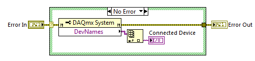
I have a NI USB-6225 DaqMx I used a couple of years. When I started with LabVIEW, I found the Daq Assistant to the best way to measure the voltage with my Daq etc. My company has purchased another DaqMx NI USB-6225 and now I have a big problem: the Daq Assistant in my old Vi does not work with the new data acquisition. I understand why there is this problem, but I do not know how to solve. I found this code on the forum who finds that Daq is connected:
The problem is that Daq Assistant do not have an entry for it, and it gives me an error if I try to run the code with a different device than the original, I used when I created the code.
Is there a way to solve this, so I don't have to convert all the Assistants Daq normal code?
Hello again,
two options:
(1) as the old software is related to 'Dev1' you must rename your new device to this alias and skip/rename the old device (and lack).
(2) rewrite your old software does not become is not dependent on the name of the alias for the data acquisition card...
It's your choice!
-
Issues of analog input DAQ-6008, voltage not zero to pin when you are offline
I use the 6008 NOR-DAQ to produce a series of tensions and then read a sense resistor using the analog input (CSR). I noticed that my analog input gives me 1.3 V, when I probe it (compared to the mass of the device), when it is completely disconnected. This changes the reading to give me a different measure of sense than expected resistance.
Why is my pin for analog input non-zero? Any help would be appreciated. Thank you!
The 1.3 V is expected. The USB-6008-and-6009 case have the strangest input of the world circuit. The input impedance is approximately 144000 ohms terminated in 1.4 V. check the document User Guide and specifications.
Lynn
Maybe you are looking for
-
Help to understand a warning in disk utility
Hi - I run regularly "verify disk permissions" because it was recommended to me. Today I came with a message that I've never seen before, and I hope someone can help me understand what it means and if I need to do something. It reads: WARNING: SUID
-
BSOD Satellite Pro A300D-14N Iridium phone to interenet connection
I have a Sat Pro A300D-14N downgraded to use XP pro.I get a blue screen when I try to connect via my phone Iridium to the interent via a prolific converter usb to serial port.The phone is not the problem. Any ideas?
-
LABVIEW USART synchronization and one of the stm32
Hi all! I try to control stm32 usart using labview to send the USART for example the baud rate settings. so to make things clear, I will give an example: at the beginning of the stm32 and labview two baudrate 9600, the user chose 115200 (on the labvi
-
My operating system is Windows 7.
-
create an animated 3d CC interaction
HelloI want to create a 3d like this WHITEvoid interactive art and design interaction using cc animate. Please suggest me step by step.Thank you