analog value unchanged.
Hello
I read analogue value through my DAQmx increased and I want to run another action when the analog value reaches its max and stop increases. How I would write my LV code to check for this condition.
Thank you
With data without noise, it's easy. Simply place a feedback node value and compare the previous value with the current value. If are equal, the condition is met.
If you have any kind of noise, you could use the 'point-by-point linear adjustment' with an appropriate history size and check if the slope is less than a certain threshold.
Tags: NI Software
Similar Questions
-
How meter and analog value FIFO synchorize
I use a card NI 6123.
Anyone knows how to put 6 analog values and the value of the counter in FIFO with the same rate: 4 k.
Thus, every second, there should be 6 * 4 k analog values and 4 k in FIFO counter value.
The problem is:
1. the counter is a numeric value, so I can't put a sampling on it. So how can I put the value of the counter in the FIFO every second of 1/4000
2. how to sync analog channels and channel meter.
-------------------------
DAQmxErrChk (DAQmxCreateTask("",&datHandler));
DAQmxErrChk (DAQmxCreateAIVoltageChan(datHandler,"Dev1/ai0:5","",DAQmx_Val_Cfg_Default,-5.0,5.0,DAQmx_Val_Volts,NULL));)
DAQmxErrChk (DAQmxCfgSampClkTiming(datHandler,"",4000,DAQmx_Val_Rising,DAQmx_Val_ContSamps,4000));
DAQmxErrChk (DAQmxCreateTask("",&ctrHandler));
DAQmxErrChk (DAQmxCreateCICountEdgesChan(ctrHandler,"Dev1/ctr0","",DAQmx_Val_Rising,0,DAQmx_Val_ExtControlled));
DAQmxErrChk (DAQmxStartTask (datHandler));
DAQmxErrChk (DAQmxStartTask (ctrHandler));
-----------------------------------
Thank you
It is possible to apply for a meter in the buffer. (this is actually preferred). Simply specify a sampling and source clock. Given that you want the meter to "lock" data from the meter to the same rate as the sample analog clock to simply specify this sample clock as the sample for the meter clock.
An example of event in the buffer (life-long) count can be found here by using an external clock (your HAVE sample digital Instruments\NI-DAQ\Examples\MStudioVC2005\Counter\Count Events\CountDigEventsBuffContinuous_ExtClk clock):...\National)
Check out this example and I think he should get you operational.
-
Analog value read with DSC Module Modbus
Hi, I have a Delta PLC with an AD converter module. I use the four analog channels and in one of them, I have a thermocouple which displays temperature data on a microprocessor thermocouple meter. However, I want to display the data in Labview. The controller communicates with labview through the DSC Module of labview with success, but I am not able to read the data. Looking forward to your help.
Found the solution. addressing to the modbus master was different for this model of plc, so I looked up the address for delta plc Modbus and the analog read list has been a success on labview.
-
analog output while keeping the value after the program
I use a USB 6001 output a simple analog voltage. Right now I'm still in the process of experimenting to see how to control my blood pressure when I noticed that, after I complete my program, data acquisition is always show the last analog value.
My VI is attached. I use the stop and remove commands at the end of the program so I don't understand why he continues to keep the last value. I used a breakpoint, so I know that program happened to stop and clear commands.
How to exit back to 0 when I close the program, assuming that there is some other way than the writing of 0 at the end of the program.
I did not find the related items, but if it don't just answer with a link.
I thank very you much for any assistance.
Tommy
The DAQ hardware is supposed to retain the last value so write a 0 before deleting the task is the right method.
-
Mise put buffer, triggered analog capture
Hello
I hope someone can help me with the please my problem. I will try and describe the situation.
-J' have a pulse train of a motor encoder attached to the counter 0 my USB daq card 6211. This is implemented to calculate the periods of pulsation. In the loop of my reading, I read 10 samples at a time. It works very well.
-I also read say 4 analog samples on each rising edge of this encoder pulse train. I implemented a sample samples finished with a clock a fast sample time. I've set up the trigger to be out PFI0 and I'm tired of the pulse train in as well as the PIN.
-In the loop, I then read 4 samples per iteration.
-When I turn the engine slowly by hand tree, I confirm that everything works as it should - I get 10 calculations period every 10 edges and I get 4 analog values every single edge.
Now for the problem.
No motor speed based on the time it takes for me to iterate in my loop 5 (for example) edges rising occurred. It's no problem for the account of the period - they are be stamped in any case. But, I only receive the last analog readings 4 - I will have missed 4 sets of data.
What I need to be able to do is to read a 2D table (for example) 4 sets of 4 points given. I can not understand how to do this well...
Please can someone help?
Thanks a lot for any assistance.
Martin
The version of LabVIEW you shouldn't question regarding DAQmx properties. On the node property DAQmx Timing, it should be "more > I convert > rate." The time interval between samples 4 is now governed by this property, AIConv.Rate. The rates on the DAQmx Timing.vi property really means nothing since you are using the external sample clock (PFI0 of your encoder). If you read several samples at the same time as a waveform, it would alter the time between samples according to this rate, but its really a best estimate because we cannot be certain that you actually provide. In VI that I posted, we only read 1 sample at a time anyway, so it really means nothing.
I hope that you can get the attribute AIConv.Rate of work, and if so, it seems like it should work for you!
-
With the help of the previous value of ro
Hello
I need a help.
Problem
-----------
-> need a previous value of the line as a line current value, one and only if the current line is 0, otherwise I have to preserve the line current value unchanged.
For example: -.
Real
---------
col1 | col2
one | 1
b | 5
c | 0
d | 0
e | 3
f | 8
g | 0
I need
-----------
col1 | col2
one | 1
b | 5
c | 5
d | 5
e | 3
f | 8
g | 8
Please help me with the solution...
Thanks in advance...
Published by: Jeanne on August 31, 2011 15:33
Published by: Jeanne on August 31, 2011 15:34It is a "thing to support:
SQL> -- generating sample data: SQL> with t as ( 2 select 'a' col1, 1 col2 from dual union all 3 select 'b' col1, 5 col2 from dual union all 4 select 'c' col1, 0 col2 from dual union all 5 select 'd' col1, 0 col2 from dual union all 6 select 'e' col1, 3 col2 from dual union all 7 select 'f' col1, 8 col2 from dual union all 8 select 'g' col1, 0 col2 from dual 9 ) 10 -- 11 -- actual query: 12 -- 13 select col1 14 , last_value(nullif(col2,0)ignore nulls) over ( order by col1) 15 from t 16 order by col1; C LAST_VALUE(NULLIF(COL2,0)IGNORENULLS)OVER(ORDERBYCOL1) - ------------------------------------------------------ a 1 b 5 c 5 d 5 e 3 f 8 g 8 7 rows selected. -
Hi all
I have a question about wireless network. Can I pass data between the nodes? Here's my setup. I have WSN 9792, WSN-3202 (node) & WSN 3230 (router Mesh). I want to get a similar measure on WSN-3202 and send it directly to WSN 3230. I try to use the shared variable network read the analog value on 3230, but receive nothing. So is there a solution?
Thank you
Andy
Hey Andy,
You must first send all data to a node through the gateway. To send data to another node, you must use a message. http://zone.NI.com/reference/en-XX/help/372802D-01/lvwsnref/wsn_host_pal/
-
Always leads when I stop my loop
Dear all,
Now, I used OR-6008, when I used case structure of program via the digital output. You can turn on and off. But when I tried to turn it on, then stop button while loop. The light that I connect to is always when I stop my program. How can I turn off which led when I stop my program?
Thank you
1. your outter loop is not necessary at all.
2. you have a lot of duplicate logic. If you're not over your threshold, of course you will be inferior to her. If you can do a lot to reduce your logic.
3 things will make a lot more sense if you convert your DAQ meter data immediately after the DAQ Assistant.
4. move your writing digital output outside the structure of the case. Also allow the timer to influence the case which is called. In this way, you can tell the exit to go simply false when your stop the loop condition is met.
5. as you collect only 1 analog value at a time, change your chart to a graph. A graph has a history built into it, which I'm sure you would like to have.

-
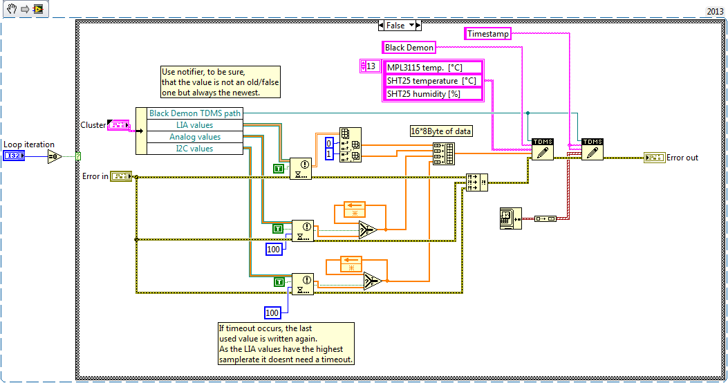
Hey guys,.
I have a clip attached.
This code snippet runs in a loop timed with maximum speed 500 ms = 2Hz.Only LIA values must always be the most recent. I2C and analog values are not sampling that fast in another loop, so it's ok, if the last value is saved two or three times.
How do I set the timeout, that the loop is still able to finish in time?
Any other suggestions how to improve performance?
Kind regards
Slev1n
In these situations, I generally use a global variable or the library of the current value (CVT) table to contain the latest data instead of the notifier. You don't need to follow a reference in this way, nor do you need to close. A little easier.
-
digital input voltage measurement
Hello.
I develop software for a test bench.
(the material has been developed in the past by someone else, and I have to use this material now)
I have to read some digital data with one nor usb 6501.
I measured the voltage on pins levels and realized that to logic 1, I get about 4, 7V, logic 0 about 3, 5V (who, after having converted to digital, is always 1).
You have an idea how I could fix this?
I thought that if I could somehow put the analog value of voltage on the PIN, the problem would be solved, but I n ' not know if it is possible.
Thanks in advance.
Katona
Hello
the 6501 low input voltage (false logic) is 0.8V and high voltag of entry is on the order of 2.0 v to 5.8V. You must use an electrical circuit or device with an analog entry order to solve this problem.
What do you think of "Schmitt Trigger"
http://en.Wikipedia.org/wiki/Schmitt_trigger
Concerning
Rüdiger
-
In my program, I have 3 analog inputs with a USB DAQ module.
I want to connect this analog values by writing them in a .lvm file.
The problem is I want to log every 1 or 10 or... seconds. So I put in a loop with a delay.
But what makes the slow program, especially when I want to stop the program.
How can I solve this problem?
Hi there,
Check out the attached VI. I did a simulation of what you want using a structure of the event. I guess this will help you.
Kind regards
Amine31
(Give congratulations to good answers and Mark as a Solution If your problem is resolved
 )
) -
Input/output USB 6008 test failure
OK I am posting this for the third time, but whenever I go back to the home page of the forum, I'm not able to find my post. If by chance I created duplicates than apologies.
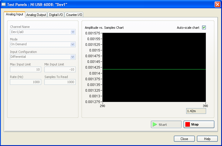
IAM in train to test the USB-6008 case I just got and decided to hang the analog of the analog inputs and see using labview VI.the wiring was done as:
http://i284.Photobucket.com/albums/ll5/bigdawg6/USB%206008%20wiring_zpss2b7hql9.jpg
the problem is that the labview VI did nothing, so I go to NI Max and try to see in test panels. But I get 1.4V constantly my same analog input value when I'm changing my analog value:
http://i284.Photobucket.com/albums/ll5/bigdawg6/AIO%20screenshot_zps9beiimbj.PNG
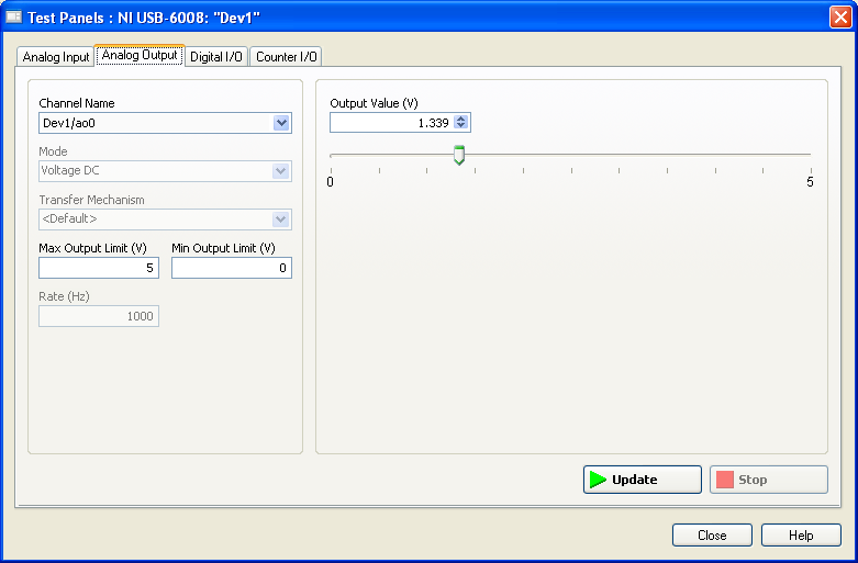
the analog output works very well since I plugged it to my multimeter and I can see the tension that I see on this Panel of test:
http://i284.Photobucket.com/albums/ll5/bigdawg6/AO0%20screenshot_zpsqpei37bw.PNG
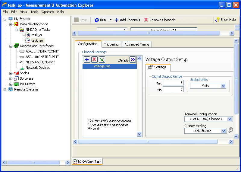
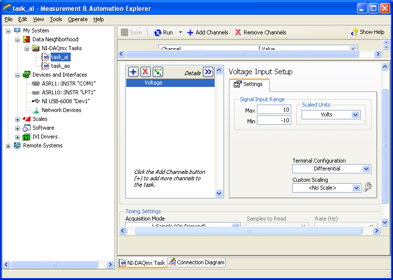
I created an entry/exit of the tasks; screenshots of them are:
http://i284.Photobucket.com/albums/ll5/bigdawg6/task_ao_zpsykmvczew.PNG
http://i284.Photobucket.com/albums/ll5/bigdawg6/task_ai_zpsix5se9yg.PNG
I am quite frustrated with all this since I'm unable to access my actaul draft. I know that 1.4 V value is from the device itself; as in the manual it says 'internal resistance divider can cause the Terminal to float at about 1.4 V when the analog input terminal is configured as a CSR', but the funny thing is that I use it in differential mode so I don't know what to do and any help is appreciated.
BTW, I did a google search and there are other tutorials onlune who seem to do exactly what I do and they seem to work very well; so I don't know what else to do.
Please don't host images on some odd third-party site. Attach them to your message.
I don't understand what you've done. The 6009 can produce only a signal of CSR in order to set up the differential input makes no sense. If you want to measure something different, try a simple battery.
-
How to connect the table 1 d to Structure box as a selector of case
Hi all
I'm able analog DAQmx Coordinated, I got component (Y) waveform and this component is of data type table 1 d (double-64-bit real) wire, according to my program I have to use the structure of the case, the selector must be values Y but labview said "you cannot connect this type of wire to the case selector (you have connected two terminals of different types).
Related question work as below:
Should I continue to move the engine while the analog values (values of Y) is lower than the preset value (for example, "10")
Greetings from the Turkey!
Best regards.
either insert a "Index Board" to address one of the points (first, last, etc.) or take the average, max , or min of the table to make a decision, according to the needs.
-
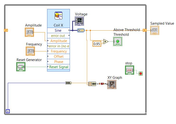
Visual control of an analogue Signal, varying in time
Hello
Here is my configuration (Fig. 1), where X coil - block "simulate Signal", which emulates an analog value that varies in some way.
This value is the result of a treatment on analog inputs... in this configuration the signal, I chose wave SIN just for simplicity.
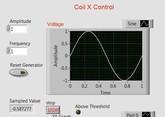
Is it possible to view the evolution of this signal in time... I mean that the "time window" on "Voltage" graph should move forward (Fig. 2).
I tried to use XY graph rather applaying (Figure 1, bottom of th), the iteration count in the loop 'While' for 'Time '.
but received an error message: "you have connected 2 terminals of different types.
What could be a solution (of course if I want it is feasible)
Thanks in advance
Pavel
Fig. 1
Fig. 2
Hi Pavel,
you don't 'manage' the history of a graphics buffer, you pay at the time of publishing. At runtime, it is fixed!
There is no difference between the periodic signals and not periodicals: you measure with a certain frequency of sampling and you decide Samper how useful are stored in the buffer. Point.
When you want to have a variable buffer (or: variable x scale) you must buffer on your own and use a graphic instead. So we're back to your original question: context-sensitive help will show you the data types expected for graphics, when you hover over their terminals!
-
I want to replace my card PCI of FPGA 7833R with new and better FPGA and the PCIe bus if possible. I want to make little changes to the LabVIEW code as possible, but I notice the potential changes that I have so far. Are there ways to get around them? Are there changes more I should provide?
1. change the device. I guess I can change it easily enough in the Project Explorer. Any trap?
2. the ISB 7833R uses integer to represent floating point for the analog I/o. Other new devices use the fixed point or floating point directly, which means that I have to do a lot of code changes. Can I make the new device to all uses for analog values?
Hosni,
Our products cRIO and sbRIO use the data type fixed point for the analog input, but all R & PCIe series PCI devices always use whole raw data to represent the analog inputs.
Your code changes should be very minimal, if any. You need to add a new target to your project and FPGA IO, but if you give the channels the same alias as they had on your previous target you'll just have to drop the FPGA VI & other elements of project (memory, FIFO, etc.) under the new FPGA target and all should be well.
Don't forget that you can try this and compile another target FPGA before still buy equipment. Since you can get your use of resources and timing reports, this could be useful to decide what R-Series Board you want to go with. Take a look at the knowledge base entitled 'how many slices My FPGA chip has it', this will give you a rough estimate of how much more great are other FPGAs, but it includes resources such as DSP, BRAM, etc.
I hope this helps!
Maybe you are looking for
-
I'm moving from my old e-mail account to my new and I would like to change the email address of synchronization automatically to my new, but I can't find this option anywhere. I know I can create new Firefox Sync account, but I'd rather just change t
-
ENVY 15 t-k200: how to find if my 15 t-K200 motherboard supports a backlit keyboard
I HAVE an ENVY 15 t-k200 AND would like TO KNOW HOW TO find OUT IF MY MOTHERBOARD SUPPORT a BACKLIT KEYBOARD
-
network connectivity is all screwed up... but I do not know what is the root cause of... This is a Console log short iOS startup Netflix, who was not able to connect and threw a dlg "there is a problem"... All my other wifi devices... MBP, Android ph
-
I met some strangeness with cascading menus which is neither intuitive nor documented. I use cascading menus to help the user to complete and modify a table containing a limited set of choices. The intention is that many of the level 1 menu choices
-
After scanning, there is no option was to where I want to be extorting digitization.
I have a HP Photosmanrt 2610, using Windows 7. Recently, I've been successful download HP Solution. So, I was very pleased to now be able to scan. But to my horror, there is no option to send my scan to Word. Now, I don't know where my scan went.