Analysis and sampling frequency
Hello
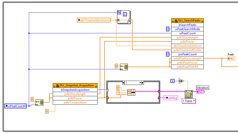
I had a device that could do 5000Hz sampling rate to get a spectrum each sampling. I put it in a while loop with vi Peak Search to find the spectrum peaks. Therefore, I would be able to get the value of 5000 peak seconds. However, the truth is, only, I could get a value of 40 peak per second. I guess there could be delays on the tops of the research.
Can someone tell me it would be possible to eliminate delay separating the part of sampling and part of the analysis? I think two while loops, first one collects all the spectra and the peaks of a seachs second. But do not know how to temporarily store data between these two parties.
It's a great idea! It's called a design ' producer/consumer '. LabVIEW is an example and a model if you want to give it a go. We are standing if you need assistance!
You have to invent it independently, however.
Tags: NI Software
Similar Questions
-
Distortion of the signal caused by the channels # sampled and sampling frequency
I am using an acquisition of data USB-6211 (250 ksps / s) and looking at the sample channels 3s 80kS. (Labview 2012)
When I taste one channel, it looks fine (1 Channel_Sampled First_250kS), but when I add another channel to be sampled, the signal is driven down and that it depends on which channel is sampled (2 channels (Different) _Sampled First_40kS and 2 Channels_Sampled First_30kS). Addition of channel 3, it pulls down even more. I also noticed that the sampling rate also distorts the signal the higher the sampling rate, the more the signal is driven down.
The acquisition of data IS sampling of signals "correctly" when I run my Labview VI my external hardware begins to read in correctly based on the distortion of the signal.
What is the cause and is there a way to fix this?
I have attached the waveform above captures and can post some if necessary.
Thanks in advance,
WBrenneman
That's exactly what ghosts means. The measurement signals later is affected by other signals. It happens usually if you have a high impedance input signal. Adding pads like you can help solve this problem by making the signal to a lower impedance.
Ghosting would probably look worse to the frequency sampling rates higher, just as you said that you had problems, as it provides less time between samples of the amplifier set new voltage level when the multiplexer allows to switch between input signals.
-
Dear all!
I hope everyone is doing well!
Well! I am a student in first year of Labview and would like an expert on this VI opinion I did. I'm learning by doing! This VI is to see the effects of sampling at different frequency. I have a LABVIEW 8.5 and uses an express VI to simulate signal, two assistant screws DAQ etc. I also play a little with the number of samples and sampling frequency.
Come to the points that I did not understand!
1. the present VI crashes and I am not able to understand what is the reason?
2. the time scale itself changes as I raise the number of samples, even if I keep the same frequency sampling.
3. in addition, the peak frequency changes with the number of samples! Why?
I hope to have your kind response!
Thanks for your time!
Tajim
Hi Tajim,
Sorry for the late reply. I made a few changes to your VI and it works very well.
You can start with the choice of the same sample rate and the number of samples of the three waveforms. In this way, all will synchronize initially.
After that, you can try to change the sampling rate and the number of samples for the waveforms. However, you should becarefull when setting very large number of samples. If you have a low sampling rate, say 100 Hz and a high number of samples, say 1000 samples it will take 10 sec to acquire all the samples. If the second DAQ assistant is running at the highest sampling at the same time, you will have an overflow of buffer of data acquisition and it may hang. Of course it is a means to avoid this by implementing different structures in LV, but for the purposes of this test, you should be ok if you just keep this in mind.
Thank you!
-
USB 6008 DI sampling frequency
Hello
I would like samples N to a digital input on 6008 channel. In the port of GOT it, it is possible to put samples/channel and sampling frequency, but I couldn't find a way to do the same for the channel of DI.
If I use MAX to read the N samples on request, I can increase or decrease the number of sampels to read but rates of mutation has no effect.
using the:
DAQmxErrChk (DAQmxCfgSampClkTiming (g_TaskHandle, "", samplesPerSecond, DAQmx_Val_Rising, DAQmx_Val_FiniteSamps, sampsPerChan));
also gives me error.
I don't know who do :-(
Concerning
RB
Hi RB,.
Digital I/o on the box USB-6008 are "static", meaning that they are controlled by the software. There is no sample clock to set the time a sample is read/written. Your software provides synchronization for DIO.
Measuring mode 'Samples on request' refers to avoiding.
Hardware timing (a sample clock) is available on most of the products OR providing DIO. As a low-cost product, the USB-6008 housing does not hardware timing for DIO.
Best regards, Topp
-
Sampling frequency and Nyquist theorem - data acquisition
Hi all
I have a rectangular steel beam that is affected with a weight of 100 kg and I would look for the modules able to sample the signal correctly.
The Nyquist theorem says that if half of the sampling frequency is higher than the input signal, it will be recorded correctly.
What I think about it before you buy a data acquisition module to find the signal of the rectangular steel beam? I will perform an analysis model by finite elements using the elastic properties or properties of plastic? Is the natural frequency of the associated structure of the input signal?
Thank you
Husband
Some technical assistance is appropriate, determine that the higher frequency component is interesting to your signal. Set your frequency of sampling to twice this value. In addition, to protect data, to build a filter of antisliasing of material it alleviates any energy above the highest frequency of interest.
Mike...
-
How to acquire with NiScope at different sampling frequencies and lengths Records?
I need to acquire the data of 2 channels of the NI PXI-5114 map two different sampling frequencies high, at the same time. Also, I put 2 different record length. Is this possible?
I understand that 'Vertical' settings can be configured for individual chains because the function 'Vertical niScope Configure' has 'channels of entry with which we can assign the desired channel. But for horizontal settings such as "min sampling rate" and the record min length, I could not find such an option to specify the channel. Would it not common to both channels?
I hope that the device is capable of simultaneous sampling and therefore channels can be configured individually to different sampling rate.
Hi AJ_CS,
Why do you have to be distinct from sampling frequencies on channels separated from the digitizer even? What different sampling rate do you want?
But for horizontal settings such as "min sampling rate" and the record min length, I could not find such an option to specify the channel. Would it not common to both channels?
You do not have an option to configure the settings of hoirizontal on a channel by channel basis because this concept does not exist in the traditional sense of the use of a scope. Compatible with the concept of IVI, an oscilloscope traditional benchtop will have only a button or a set of buttons for setting the parameters of synchronization of the unit. There is therefore no horizontal configuration to separate channels on the scanners NOR.
I hope that the device is capable of simultaneous sampling and therefore channels can be configured individually to different sampling rate.
Similar to a traditional benchtop oscilloscpe, the device is capable of simultaneous sampling. But as mentioned above, the channels can not be configured for different sampling frequencies high.
However, you can ignore data that you think is not relevant. For example, if you assign 100MS/s CH0 and CH1 to 50 MS/s, then you throw all other samples.
Alternatively, you can use separate scanners (a channel on each digitizer) and configure them to taste at different rates. You can set frequencies of sampling on scanners NOR separated and even synchronize them with TClk.
-Andrew
-
Synchronization of the inputs and outputs with different sampling frequencies
I'm relatively new to LabView. I have a NOR-myDAQ, and I am trying to accomplish the following:
Square wave output 10 kHz, duty cycle 50%.
Input sampling frequency of 200 kHz, synchronized with the output that I get 20 analog input samples by square wave, and I know what samples align with the high and low output of my square wave.
So far, I used a counter to create the square wave of 10 kHz, display on a digital output line. I tried to pull the document according to (http://www.ni.com/white-paper/4322/en), but I'm not sure how sample at a different rate than my clock pulse. It seems that this example is intended rather to taste one entry by analog clock pulse. There may be a way to create a faster clock (200 kHz) in the software and use that to synchronize the analog input collection as well as a slower 10 kHz output generation square wave?
I eventually have to use the analog inputs to obtain data and an analog output to write the data channel, so I need the impetus of the square wave at the exit on a digital PIN.
How could anyone do this in LabView?
Hi Eric,.
All subsystems (, AO, CTR) derive from the STC3 clocks so they don't drift, but in order to align your sample clock HAVE with pulse train that you generate on the counter, you'll want to trigger a task out of the other. I would like to start by a few examples taken from the example Finder > Input and Output material > DAQmx. You can trigger GOT off the train of impulses, start by Gen digital Pulse Train-keep -you probably already use a VI like this to generate 10 k pulse train. AI, start with an example like Acq Cont & chart voltage-Ext Clk - Dig Start.vi-you'll want to use the internal clock so just remove the control of the "Source of the clock" and it uses the internal clock. From there, simply set the "Source of the command" either be the PFI line generates the meter, or ' /
/Ctr0InternalOutput '-assuming that you are using the counter 0. You'll want to make sure that the start of the task HAVE faced the task of counter I is ready to trigger off the first impulse. They should be aligned at this point. For debugging, you can use DAQmx export Signal to export the sample clock - you can then brought the train line and the PFI pulse to make sure that they are aligned.
Hope this helps,
Andrew S
-
Doubts about the sampling frequency when the production and acquisition
When the generation and acquisition of samples, the maximum sampling frequency is the maximum sampling frequency Council divided between the generation and acquisition of task number?
Thank you
Hi Houari,
You should read the specifications of your box DAQpad!
It is clearly said: entered analog = 200kS/s rate sampling, but analog output = sample rate of 300 s/s or even just 50 s/s for the hardware timing!
-
What is the relationship with the sampling frequency and number of samples per channel?
In my world, if I wanted to taste 10 seconds 10 Hz (100 s/ch), specify a rate of 10 and a number of samples of 100. This would take 10 seconds to return data. The task does not appear to behave this way. No matter what rate and the number of samples, I chose, I spammed with data at 1 Hz or more.
What I am doing wrong?
This problem is resolved by making a request for telephone assistance. It turns out that the minimum sampling frequency of the NI 9239 is 14xx s/s. I don't know why there is a minimum sampling frequency, but now I have to go to the next question discussed at this link:
-
determination of the sampling rate and the frequency waveform data record
Hello
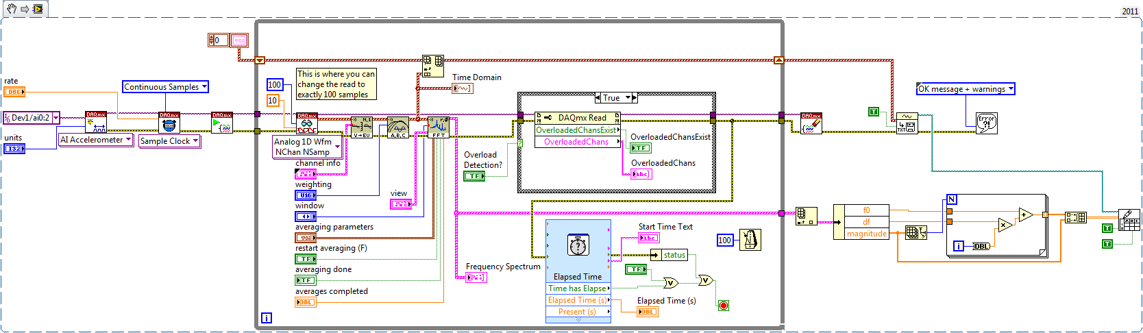
I write a simple program that collect data from a triaxial accelerometer input, convert it to a frequency spectrum, and then save the time domain and the frequency of the waveforms in an external file separated. I don't understand how to set the sampling frequency, however. On the DAQ Assistant, I updated the acquisition mode "Samples continues" and read samples is 2 k, which corresponds to the total number of data points that are collected. How can I program sampling for awhile, it 30 seconds, for example? Wouldn't be better to set up a trigger, as it will continue to collect data up to what I told it to stop?
I also want to save waveform data in a separate file that can be easily seen by other computers that have not installed Labview. I have currently the program put in place to convert a text string of the waveform of the time domain and then save it in a text file or a spreadsheet. It works fine, but I would also like to record the frequency wave, which is a different type of data. How can I do this or is there a better way?
My program is attached. Thanks for your help!
Here's how you can use the shift register to build the table, and also where you can choose to play exactly 100 samples per while the loop iteration.
Brian
-
Hello
In the code in the example attached, I create a task with a single channel of AI.
I get the maximum sampling frequency using DAQmxGetDevAIMaxSingleChanRate (or DAQmxGetDevAIMaxMultiChanRate), both return the same value of 1351 s/s.
When I try to configure the sample calendar using DAQmxCfgSampClkTiming at the maximum sampling frequency clock he does not accept the rate and returns the following error. Note that the error message shows 2 channels, even if only a channel has been added.
OUTPUT:
DAQmx error:
Sampling frequency is greater than the maximum sampling frequency for the number of specified channels.
Reduce the sampling frequency or the number of channels. The increase in the conversion rate or
reduce the time of the sample can also mitigate the problem, if you define one of them.
Number of channels: 2
Sampling rate: 1.351351e3
Maximum sampling frequency: 675.675676Why the device driver thinks I have 2 channels in the task, when a channel has been added?
Please find the code to reproduce this problem attached.
Kind regards
whemdan
The MathWorks
Hello w,
By default, the ENET/WLS/USB-9213 in NOR-DAQmx module has the AI. AutoZeroMode the value of the DAQmx_Val_EverySample property. This causes NOR-DAQmx acquire the channel of the internal path of the unit (_aignd_vs_aignd) on each sample to return more specific measures, even if the operating temperature of the device moves over time. If you need the sampling frequencies higher than this allows, you can call DAQmxSetAIAutoZeroMode(..., DAQmx_Val_Once) (who acquires the formatting string when you start the task) or DAQmxSetAIAutoZeroMode(..., DAQmx_Val_None) (which disables the setting entirely).
Note that for measures by thermocouple with cold junction compensation sensor of the 9213 NOR, NOR-DAQmx acquires channel built-in CJC (_cjtemp) on each sample as well, for the same reason.
Brad
-
Reading and samples the sampling frequency using a fast external clock
Hello
I use an NI USB-6212 box to launch a search engine for combustion. I have a pressure sensor in the head and a wheel on the crankshaft. I use the beats A Quad channel of the rotary encoder as a sample external to the pressure with the sample clock. The idea is that I want almost the same number of points in each trace of pressure so that it is easy to average together. I seem to be able to do this at low speed, but I'm having issues at high speed.
Can someone tell me what I should have my sampling rate and samples to read together and how it effects my sampling when using an external clock? Samples per channel will affect the size of buffer and that matters? When I was high (10-100 kHz and about 1/10 * rate for samples to read) it barely read but as I put the lowest and lowest he read faster. Play with the settings a bit seem to affect how well it samples at different speeds. The engine is running at 3600 rpm and my encoder puts out 2500 pulses per turn on one channel, I'm looking at a frequency of 150 kHz effective sampling. However I didn't sample program with the engine operating at full throttle. I hung on the output of the encoder up to a scope and reads very well.
Are there opportunities the filter counter that I see in the manual of 621 x is enabled inadvertently?
Thank you
Xander
Xander18,
I suggest you move your screws initialization outside the while loop, as well as your narrow DAQmx VI. On my side, it looks like a new task is performed for each loop, which takes time. That a try and let me know how it goes.
-
generation of buffer desired waveform ╔chantillonnage clock and clock frequency sample resulting
Hello, I'm trying to generate a square wave on an ongoing basis for NI6221 DAQ to 2 kHz. I use the example of Cont Gen tension Wfm - Int Clk.vi, which works great for my needs. However, the synchronization frequency setting is sometimes different frequency resulting, according to the choice of the samples and the Cycles / buffer. Tracking dozn the origin of these variables, all come from the nodes property of the moment-DAQmx in Buffere waveform generation (multi) .vi, where the input and output frequencies are not the same. Now, why is it so? What is the way the rate is calculated? I guess it's related to an internal approximation of the Council divided by sweep sampling frequency, clock but how exactly?
I found some notes in the help (see figure), with a few diagrams of the oscillators according to the DAQ (M type) card, but then I'm lost.
Thank you very much
Virgilio
The AO sample clock is generated by dividing down the time base. If you select a clock frequency sample that can not be achieved by dividing the time by an integer base, the sampling clock frequency will be rounded up to the available sample rate nearest (it might be interesting to note that tasks HAVE always round the frequency rather than rounding to the nearest available).
For example, the maximum time available for AO internal base is 20 MHz. If you select a sampling frequency of 300 kHz, this wouldn't be possible (20 MHz / 66.66666...). Instead, ~298.5 kHz will be used (20 MHz / 67).
Best regards
-
Sampling frequency of HAVE is incorrect for simulated ENET-9213, WLS-9213, and USB-9213
Hello
ENET-9213, WLS-9213 simulation and devices USB-9213, I'm able to correctly get the sampling frequency of I = 1351 samples/s using DAQmxGetDevAIMaxSingleChanRate, which is incidentally on the value of spec'ed of 1200 s/s.
However, when I create a task and add a voltage channel and then HAVE the sampling frequency of the task of query, I get a sampling rate of only 9 samples/s. I tried the same code with other devices and I get the sampling frequency corresponding to the device data sheet, it seems THST this problem is limited to 9213 devices.
Why sampling returned by the task using DAQmxGetSampClkMaxRate rate returns than 9 s/s.
And why the rate of conversion of DAQmxGetAIConvRate only 18 s/s.
I enclose the test code which may be used to reproduce this problem.
Kind regards
whemdan
The MathWorks
Hello
When I tried this with a USB-9213 simulation, I used the Sample clock Max Rate, as well as the Rate.vi of AIConvert:Max property node. I could see that for 1 channel, I could spend up to 675.67/s, and I couldn't for 16-channel get79.49S/s (which total is equal to 1271 S/s, which is in the specifications). The multichannel and single channel, I could get an AIConvert Max Rate of 1351.35.
Something that could happen is that you do not explicitly set this device runs in mode high speed. You'll want to set the property Get/Set/rest AI_ADCTimingMode channel at high speed, and you should see much better results in this way.
Something else to note - I use DAQmx 9.0
-
WLS-9163 and 9211, sampling frequency of evil?
Hello!
I have a WLS-9163 with 9211 mounted module. I have connected a single thermocouple type K to the analog input 0.
I can connect and perform measures wireless. However, I can make only 7 s/s without error message.
I get the following error message when I try to taste 14 s/s in the configuration of WLS-9163.Error-200081 occurred to the DAQ Assistant
Possible reasons:
Sampling frequency is greater than the maximum sampling frequency for the number of specified channels.
Reduce the sampling frequency or the number of channels. The increase in the conversion rate or reduce the period of the sample can also mitigate the problem, if you define one of them.
Number of channels: 2
Sampling rate: 14.000004
Maximum sampling frequency: 7.142857
Channel name: _WLS-14049AF-2/_cjtempWhen I use the 9211 in a cDAQ-9172 configuration I can acquire up to 14 s/s of a single channel with no problems at all.
Somehow he thinks that I chose to take measures to channels, that is not the case.
I use Labview 8.5.1 with hardware drivers of 2009-10 with Windows XP SP3.
Is this something you've heard before?
Best regards
MattiasMattias salvation,
Your task is also reading the CYC on the unit once for example, if you are done reading of two channels. Reading of the CCM (it's the .../_cjtemp in the error message) is required to return a value of temperature measured from a thermocouple.
Kind regards
Kyle
Maybe you are looking for
-
Recovery of product - add a 2nd partition without deleting the 1?
HelloI've read dozens of messages about the recovery of product, but I still wonder. I have a Satellite M30 - 344 (year 2003). Windows does more (blue screen with caller bad pool 0x000000c2). I don't have 1 partition - can I now use expert mode and a
-
I tried the time servers following Internet:Time.Window.comTime.nist.govNIST. Time.govtime - nw.nist.govtime - a.nist.govtime - b.nist.gov When I'm in the settings window of time Internet and I click on update now, I get the following error message:
-
Original title: Corel Software-related Error Messages, I tried to delete I'm getting 2 error messages associated with a Corel program I tried to remove it. The messages are: 1. "HKEY_LOCAL_MACHINE\" value: "ConfigDir" not found in the registry2. the
-
Import of music in WMP = duplicate files?
If I import my music folder (I usually use itunes) in Windows Media Player, WMP would make duplicate files or a separate folder for my music? Thanks much in advance =).
-
What are the differences between HP7520 and HP7525?
I have a HP7515 that I love, but the paper source has failed. I'm looking at HP7520 and HP7525, but I can't find what the differences are. Where can I find a comparison between the HP7520 and the HP7525?