Analyze the attribute
I have a XML as below. How can I retrieve the values of 'data' using qml?
Take a look at https://developer.blackberry.com/cascades/documentation/device_platform/data_access/working_with_xml...
You can write C++ wrapper to parse XML and then call its methods of QML to retrieve the values of 'data '.
Tags: BlackBerry Developers
Similar Questions
-
Hello
First of all that I must say I just starting with control of the instrument using Labview. For this reason, it is possible that the problem I have is easy to solve. However, I am looking for any solution for the forum, but unfortunately I can't fint anything.
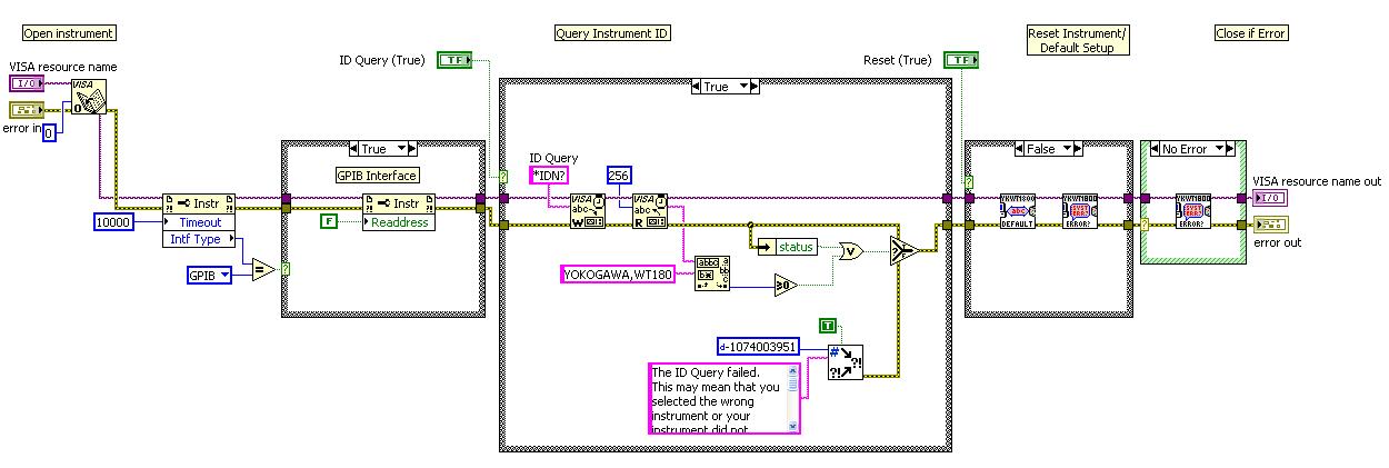
While the situation is this: I'm looking to plug a power Analyzer (Yokogawa WT1800) with the PC through GPIB. To achieve this, I use the USB/GPIB Interface of Agilent 82357 B. The connection is done correctly because I can see and communicate with him through the Explorer NI MAX.
In order to achieve control of the instrument using Labview, I downloaded and installed the driver of Yokogawa WT1800 (Driver instruments ykt1800) using the NI Instrument Driver Finder tool. The problem I have is that when I run the examples, I find the following error message:
Error 1073807330 has occurred to the property (arg1) node in Yokogawa WT1800 Series.lvlib: Initialize.vi-> Yokogawa WT1800 series continuous measurement Normal.vi
Possible reasons:
VISA: (Hex 0xBFFF001E) the State specified, the attribute is not valid or is not taken in charge as defined by the resource.
I tried to change the input of the open Visa arguments vi because I think that this is where is the problem, but I can't reach any solution. The following image is attached to the block diagram of the initialize.vi:
Any help is appreciated.
Thank you.
I suspect the redirect property. Try to remove it.
-
Change the Type of the attribute at the request of the View object
Hi all
I use JDeveloper 11.1.1.6. I am trying to achieve the following problem.
My Table has a column of type VARCHAR2, but this field is to store, say, displayed in canonical format "YYYY/MM/DD hh '. I want to show the date in a nice format, as October 30, 12 ' and be able to use the datePicker adf (date. MinValue) on the attribute.
So I created an entity object, and I changed the type of the attribute of Date String.
I also created a ViewObject and the test on request module retrieves a date but seems to not understand the canonical format and date it recovers is wrong (something like 5049-02-20 12:45:30.45).
Since then, I work on EBS I oracle API access and so on, so I changed my query View object;
SELECT St St myEO.ExpiryDate-> FND_DATE.canonical_to_date (myEO.ExpiryDate) SELECT as displayed in St St. (FND_DATE.canonical_to_date would be the same thing as to_date (date, format))
When I run AppModule, NICE! It works, it retrieves the date without time and if simple format to give the attribute I can even get the format I wanted.
The problem is that when I try to update and validate changes to DB, (I replace the doDML so I can analyze my Date to a string with the format YYYY/MM/DD hh: mm: as is supposed to be) I can't even the part update. Complains in the framework;
Invalid state, another user has changed the line and blah blah blah and the problem is here:
(oracle.jbo.RowInconsistentException) Houston-25014: another user has modified the line containing oracle.jbo.Key [592674 primary key].
[178] compare entity did not attribute display
[179] original value: 2013-06-28 (that I ran with my FND_DATE.) Procedure CANONICAL_TO_DATE)
[180] target value: 5048-02-21 22:47:53.0 (I guess that the automatic distribution or conversion of the original string)
OracleSQLBuilder [181]: ROLLBACK WORK point registration "BO_SP".
[182] DCBindingContainer.reportException: oracle.jbo.RowInconsistentException
Any suggestion? I'd really appreciate it.
Edited by: Alejandro T. Lanz on 1st November 2012 06:34Well, in short :):
When you try to update the line, frame checks the data in db and cached (from the entity object) value is different from the db value (because you Date and String objects), so that it will throw oracle.jbo.RowInconsistentException exception.Dario
-
Satellite M100 - I can't analyze the CPU temperature
I am a Toshiba Satellite M100 series owner (Core Duo T2300, X 1400, etc.). The problem is that I can't analyze the CPU temperature variations in such popular application such as Everest or Notebook Hardware Control. Also any other software provided by Toshiba and installed already on my HARD drive does not include some CPU diagnostics, including temperature changes!
The only software that seems to work is the HWiNFO32 so there is a thermal probe inside which specifies that Centrino Duo processor temperature, but this software is not very user-friendly :(
There is a request for Toshiba do something with this... I've updated the BIOS in my template for a version 1.70, but this does not change I could easily noticed (or is he?) :(
Hello
In most cases applications can give you info on the hardware and the different settings but the temperature of the CPU in most cases is not visible. Toshiba has no tool or utility that can read or modify.
BIOS update has absolutely no influence on it. Satellite M100 is one of the latest devices and I really don t understand why it is so important to you. Important in my opinion is the stability of the system, the operation of the equipment and no problem with the software you are using. Am I wrong?
-
Google Cloud Print setup - impossible to analyze the capabilities of the printer
I am trying to add my CP1525nw to Google Cloud Print as a Cloud, and not as a LOCAL printer printer, however every time that I add my eprint email I get the following message. "Impossible to analyze the capabilities of the printer" - I tried for public and private use for eprint settings with no luck.
Any help would be greatly appreciated. I tried the reset email with no luck...
EDIT - 01/04/11:
I chatted with HP support, and although the representative was extremely courteous, they could not help me. The support agent assured me that the matter would be taken at a higher level and looked so I hope that we can have a resolution here shortly.
EDIT - 04/04/11:
Received a response from the original HP rep that I chatted with online. In short, it was not able to find a solution and States, that the question will be sent upwards to the highest level of technical support from HP... We shall see.
EDIT - 05/25/11:
After 2 months of waiting, HP has corrected the problem. Don't forget to upgrade to the latest firmware and check all the settings before continuing.
The fix came from the side server - this defiinitely had nothing to do with the firmware. I've updated on Monday for the latest on the HP website and it was still not working. The gentlemen of tech support that helped me sent me an email a few hours after we talked, saying the sea a fix was to come.
Nevertheless, I am happy without worrying how the fix is here!

It took only 2 months to fix, but I'm glad it is.
-
I want to replace the strings of the label of the ring (value/label pairs) after starting the program with the strings extracted from the Excel worksheet or a text file. I know how to implement this part but I do not know how to set the label with the command of the attribute. I found the command to set the label of the ring, but I want to change the label value/label pairs so that the user can change them according to the names of devices:
Value label
1 Device1
2 Device2
3 Device3
Thank you for your help.
Leszek
Hello
Take a look at InsertListItem (), ReplaceListItem () and DeleteListItem ().
Good luck
Wolfgang
-
Set the attributes for dynamic data waveform t0 zeros?
HI -.
A beginner to labview here, so please be nice ;-)
I have a simple setup with mainly express screws where I follow the steps below in a while loop
(1) collect signals with the DAQ Assistant, that generates dynamic data. It is the collection of samples of N
(2) changing the attributes of the dynamic data using the express VI 'Set the Dynamic Data attributes'
(3) storing dynamic data revised to a file by using the writing to the file of the measurement.
The problem I was see is that whenever I have insert the express VI 'Set the Dynamic Data attributes' in the data flow, I find myself with a file where synchronization of the signal (i.e., the waveform t0) was cancelled. This seems to happen any dynamic data attributes, I edit. For example, even if I try to set the name of signal I find myself with out having a nulled-out t0
FYI, I'm using Labview 2009 9.0f3, 32-bit
I have attached a code simplified showing what looks like a bug to me. Any help would be appreciated!
It looks like a bug to me as well. Also, unlike other screw Express, you do a right click on it and select open the face before seeing what the problem is. It's pretty simple to find a work around. I converted to a waveform, has obtained the t0 and handed that back as the timestamp for the signal of slected.
-
How to analyze the data of 10 bytes encoded in the HH306 of Omegatte data logger/thermometer?
I am trying to write a simple code for a HH306 of OMEGAETTE thermometer/travailleursduweb.com data recorder.
That is the problem. I communicate with the device via RS - 232, using Labview 8.5.1 and windows xp. I ask her for "all the coded data", which is actually the only option. He returns 10 bytes of encoded data, the manual describes the meaning of each byte and I understand that. The problem is that I can't analyze the information for use in labview, for example: I want to extract the temperature and simply display it.
on request, I get: 10bytes (read as a string from the serial port read buffer): display HEX: 02 00 A8 48 FF EF B6 49 B6 03 is perfect, and what I expect. Display codes: \02\00\A8\B6H\FF\EF\B6I\03 The Normal display is a series of special characters, I don't understand, especially since I don't think they are ascii characters that must match returned hexadecimal numbers! For the life of me, I can't understand how to extract the information (what are the 48 6 hexadecimal display) of what is returned. All string manipulation functions seem to work only on what is given in Normal view. (The 4th and 5th byte of the data are the codes of the BCD for temperature: for example the temperature was 64.8 degrees farenheight when I took this reading).
Can someone help me to analyze the data returned by this device?
Ok... I think that I thought about it. I found this: http://digital.ni.com/public.nsf/websearch/77C8F61D36F5A23086256634005ACB38?OpenDocument.
I guess the normal display garbled is corresponding to each hexadecimal ascii characters. I'm just not used to seeing characters beyond the decimal number 127 ascii or hex 7F.
So, basically, to analyze the 10 bytes of data:
(1) break the string read from the serial port in the 10 ascii characters (using String subset vi)
(2) son of each output string in the left input of 10 separate Type vi Cast.
(3) wire a constant U8 in each terminal 'type' VI Type Cast.
cables of 4) the chain of each Cast of Type vi output to the input of a number hexadecimal string vi.
(5) concatenate or use as you wish as hexadecimal numbers (now in string format) which cause.
See you soon.
-
analyze the 2 bytes at a time series data
I am acquiring 8 bytes of serial data and I would like to analyze the data in 2 bytes of data, so that I find myself with 4 measures of different temperatures. I tried a lot of things that I found in the forum, but I can't make it work. I have attached the VI is using string function analysis, but I'm not very familiar with this function. My fault my serial data so that you can see the data that I get.
Thanks in advance for your help
Lowski
See if it's to help you get started. You must understand the scale yourself.
-
Analyze the text and identify which columns contain unpaired data
Hello world
I want to write an elegant solution in LabWindows-CVI to accomplish the same thing as what I implemented in LabVIEW.
The client does not use or do not own LabVIEW. I have to code the solution in the CVI.
Order to simpify the explanation of what it is that I try to do, I wrote a small example in LabVIEW (see below):

The code needs to parse a string to determine which data column includes unpaired. To do this, I first removed the unwanted text on the top and bottom. I also removed the extra space between the 2 groups of data by replacing the two separated by one to facilitate the next step. The result string has been converted to a table 2D-string. Only the columns you want to search for remained (total of 16 columns). Table 2D has been transposed as the table 1 d of research searched each line, I want to look in each column. 2D table transposed in its entirety was sought of all no corresponding values, which fills a table 1 d of boolean. I converted the table 1 d of boolean to a number to see if data 'no match' has been found. If none have been found, the value would be zero.
I need help to encode this in CVI.
Thank you very much
RayR
Ray, aspect string makes me think that it's a memory dump, while I designed a solution that analyzes the values of the whole of the chain and operates on them, instead of working on the string itself. Take a look at the attached example which should be what you're looking for. feel free to add comments or ask for clarification on some instructions if you need.
-
I try to open a com port Seraglio in LabVIEW get this error:
VISA: (Hex 0xBFFF001E) the State specified, the attribute is not valid or is not supported as defined by the resource.
It occurs in ISA set up a Serial Port (Instr) .vi and seems to be related to the speed of transmission. If I use anything else than 9600, I get this warning. I need to use 115200. I can open successfully to other com ports at 115200.
I am able to talk to this device using other Terminal programs to 115200 without problem. It is only through LabVIEW and NI MAX.
The Unit presents itself as "Stellaris Virtual Serial Port (COM12)" in deveice Manager.
Is there a way to get around this?
Thanks in advance!
-
Different behaviors in MAX vs LabVIEW when writing the attribute IMAQdx GigE
Hi, I'm controlling a Dalsa GigE camera in LabVIEW RT using IMAQdx. Apart from a few quirks with interface we are image acquisition without a lot of problems at the moment.
However, there are one or two issues that are confusing. In this case, it is possible to set a MAX attribute (an attribute of command that tells the device to perform the internal calibration), but when you set the attribute in LabVIEW, the error 0xBFF69010 (-1074360304) unable to create the attribute is thrown. See the attached images.
I check if the attribute is writable before making an entry. It is, however, the write failed, and read the iswritable attribute and then returns false. In MAX, I can write to this attribute with no problems.
I have to set up/read/write in my LabVIEW code that makes MAX. MAX writes all the attributes (based on the values in the XML file) when he opens the camera or he reads simply all the values of the camera. When LabVIEW opens a reference camera does perform the same steps that what MAX - I'm trying to figure out what could be the difference between MAX and LabVIEW, which might be the cause of this behavior.
Any help will be appreciated.
AnthonV wrote:
Hi, I'm controlling a Dalsa GigE camera in LabVIEW RT using IMAQdx. Apart from a few quirks with interface we are image acquisition without a lot of problems at the moment.
However, there are one or two issues that are confusing. In this case, it is possible to set a MAX attribute (an attribute of command that tells the device to perform the internal calibration), but when you set the attribute in LabVIEW, the error 0xBFF69010 (-1074360304) unable to create the attribute is thrown. See the attached images.
I check if the attribute is writable before making an entry. It is, however, the write failed, and read the iswritable attribute and then returns false. In MAX, I can write to this attribute with no problems.
I have to set up/read/write in my LabVIEW code that makes MAX. MAX writes all the attributes (based on the values in the XML file) when he opens the camera or he reads simply all the values of the camera. When LabVIEW opens a reference camera does perform the same steps that what MAX - I'm trying to figure out what could be the difference between MAX and LabVIEW, which might be the cause of this behavior.
Any help will be appreciated.
Hi AnthonV,
"Weird" is a good way to describe the Spyder3 when it comes to the GigE Vision/GenICam interface (as opposed to the Dalsa driver that communicates using custom commands via ethernet camera series)...

The Spyder3 has many questions focused on the calendar. It is possible that the time between the opening of the camera and the setting of this function is different by MAX vs your code in LabVIEW. In addition, there are some cases where MAX will be deletes the error to display. Ignoring the error indicated vs you see the feature to take effect in both cases?
The base between MAX and LabVIEW behavior is the same. In both cases when you open the unit all parameters are responsible for our camera file that has the registered device settings. This file is created the first time that you open the unit and are updated every time you click on save to MAX or call an API function to save the settings. In any case, I know that the Spyder3 has various questions backup/restore the settings of our camera files.
I suggest talking with Dalsa on the issues you are experiencing. They might be able to put up with a newer firmware that addresses some of these issues (we have worked with them in the past to identify several of them).
Eric
-
How to take the attributes separately circle
Hi all
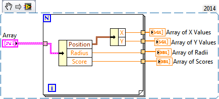
I need to consolidate the attributes (such as RADIUS, Centre, Center XY) function IMAQ circles detect circles. For example, all positions must be grouped in an array. I couldn't separate them.
I tried a few things to do. I add my last essay as an attachment. Because I am new to Labview is not a good way. If it is not a good way to do this task, I'd be happy to hear the different methods or modifying the VI would be appreciated

omersevinc wrote:
Hi all
I need to consolidate the attributes (such as RADIUS, Centre, Center XY) function IMAQ circles detect circles. For example, all positions must be grouped in an array. I couldn't separate them.
I tried a few things to do. I add my last essay as an attachment. Because I am new to Labview is not a good way. If it is not a good way to do this task, I'd be happy to hear the different methods or modifying the VI would be appreciated
The vi circle IMAQ detect returns an array of clusters. Each cluster contains a cluster of position x and Y information (float single precision), RADIUS (double precision float) and score (double precision float). You can separate these first, getting a single element of the array. In the excerpt below, I use a tunnel indexed in a loop to do this. Then use the Unbundle based on the name to separate the three elements of the cluster. You will need to reuse the Unbundle based on the name out of X and Y from the pole Position. Then just run all the values out of the loop with a tunnel indexed For you. Hope this is what you are looking for.
Kind regards
-
Grab and the attribute configuration example VI
Hi all
I'm trying to get the attributes of a GigE camera. I use VI example in IMAQ "setup.vi grab and attributes. I have problem of understanding, can someone please clear my doubts below?
(1) in the diagram-block before and after the block "update attributr tree" property with David Panel updated node is used. Until the 'update attribute tree' block wa together true and after the block, he has been set to FALSE. What is the need to use it twice, especially after the attribute tree update"block".» What is the need of it affecting FALSE?
(2) what is the logic behind using block 'cancel the acquisition configuration' immediately after 'configure acquisition? Before grab frames, if we cancel acquisition block, how executives are acquired?
Concerning
Neo
NEO6 wrote:
If affecting true allows to get the updates to defer attributes in a short time, then this makes sense again it affecting false?
If you don't set it to false, you frontpanel does not refresh.
I found no application folder data, under the path you mentioned. I'm using LabVIEW 2011 SP1. My idea is to save your setup file with the settings changed each time when I hit the run button and reuse the file attributes if my results are satisfactory set of parameters withose
The location of the file is OS dependent. Under Win7 it's C:\user\All Users\Public Documents\National Instruments\NI-IMAQdx\Data
You can use IMAQdx Write Attributes.vi to register your attributes in a configuration file
Concerning
Neo
-
How to control the attributes of the sliders with Boolean button
Hello world
I would like the attributes of the control sliders by clicking a Boolean. For example: when I click on my button, I want the cursor to disappear or change color...
How can I do this? I saw that I can select cursor style, color slider etc. in the property of the XYgraph node, but I don't know how to use it.
Any idea?Best regards
MartinO.You first need to identify your cursor active then you can set the visible property of the cursor in your Boolean control. Creating a property node, drag to show two properties, set the first wire of ActCrsr years the number of cursor for it (0 for the first slider). Now select Cursor.Visible for the second property and wire your Boolean instead. You can add other properties after that.
Ian
Maybe you are looking for
-
get the MAX from the task frequency
Hello I would like to know if it is possible to obtain the frequency configured in MAX for a particular task in LabVIEW. This is in order to launch the task set by the user in LabVIEW, as set in MAX: channels, frequency etc... I tried differentDAQmx
-
I have a 700 PIF with a hardware error 03130031-2618. Can someone tell me what this means?
-
vWorkspace AppPortal Desktop Integration does not start
Hello I'm trying to accomplish to publish applications published to the user's desktop / Start Menu on their VDI machines. Inside of a VDI machine, I installed bit vasclient32 and during the installation I checked the box, automatically integrated wi
-
Can I send job work/off Windows 7 connecting to a laptop running Vista with no problems?
I bought a dell 10.5 "with Windows 7 and WIFI already installed and activated. LIKE THE THING! But I don't know if I can send my work WIFI to my laptop elsewhere in safty. I am a nooby, any advice will be welcome, so thank you in advance!
-
Are registry cleaners and defrag (s) necessary?
I was wondering for about a year now...