Analyzers of vector signals OR, in real time of tektronix and tests EMC spectrum analyzers
Normal
0
21
fake
fake
fake
PT - BR
X NONE
X NONE
MicrosoftInternetExplorer4
/ * Style definitions * /.
table. MsoNormalTable
{mso-style-name: "Table normal";}
MSO-knew-rowband-size: 0;
MSO-knew-colband-size: 0;
MSO-style - noshow:yes;
MSO-style-priority: 99;
MSO-style - qformat:yes;
"mso-style-parent:" ";" "
MSO-padding-alt: 0 cm 0 cm 5.4pt 5.4pt;
MSO-para-margin-top: 0 cm;
MSO-para-margin-right: 0 cm;
MSO-para-margin-bottom: 10.0pt;
MSO-para-margin-left: 0 cm;
line-height: 115%;
MSO-pagination: widow-orphan;
font-size: 11.0pt;
font family: 'Calibri', 'sans-serif ';
MSO-ascii-font-family: Calibri;
MSO-ascii-theme-make: minor-latin;
MSO-hansi-font-family: Calibri;
MSO-hansi-theme-make: minor-latin;
mso-fareast-language: EN-US ;}
1. how to work if vector performance of or
Analyzers of signals compare to Tektronix real-time spectrum analyzers?
2 can you emulate Tektronix FFT
processing overlapping?
3. is it possible to use vector of NOR
Analyzers of signals of compliance EMC and/or test preconformite? Is there some
companies use it successfully? Need a special or custom software?
Thank you
Hi emc2006
I'll answer your questions separated by your topics:
1 - What is the factor that you want to compare between these two products? In the link below, you will find the performance of the NI PXI-5660 RF Signal Analyzer system.
2. you can develop this feature of programming in software Application development, i.e. of LabVIEW.
3. Yes, NI´s vector signal Analyzer could run preconformite or EMC compliance analyses. In the same link below, you will find in the subdivision of Applications.
http://zone.NI.com/DevZone/CDA/tut/p/ID/4298
Concerning
Napoleao
Application engineering
National Instruments
Tags: NI Products
Similar Questions
-
Output signals controllable DAQmx (real-time)
Hello:
I have a question here.
It is quite difficult for me, and I can't find any bad example and discussion.
Hope that some people give me some information for me to look it up.
--
I am trying to generate an analogue signal into a DAQmx device (I have an and uses it well) to control another device.
The output signal must be the sum of a background signal (which is decided, let's say a sine wave) and another control signal.
The control signal depends on the entrance of real-time control, for example by using the horizontal location of the mouse to the value of the signal.
The background signal is designed in advance and it will run continuously (should not be stopped once the system starts to ensure that synchronization between each devices).
At the same time, the control signal should be continuous. (if there is no new entry, it uses the default value or the last entry).
--
I have almost no idea on how to do it.
As far as I know, needs only one daq task to write the signal, and then she runs after.
The control signal is a thing in real time, so the task needs to be updated very quickly.
But regeneration tasks cost 50ms ~ on my computer (and I used the low levels rather than the DAQ assistant Renault).
Also, in this case, my background/control signal will be be stopped every time that when the task is regenerated (and this makes my synchronization failure.)
I checked DAQmx in real time, but couldn't find a few examples of tris and seems it isn't for my application actually (?).
A possible solution, I came is cascading my two signals once they are generated by my DAQ hardware. And then I can use an a/o to be the background signal and use an another a/o to be the control signal.
However, my control signal is always interrupted between each loop, and the method of external cascade seems not smart.
Or data acquisition is not perhaps suitable for this application?
--
Hope that some people give me some information and then I can check their.
Thank you very much
Hi Jhensi,
How the example provided was for you?
With respect to the delay that you experience, there is always a slight delay incurred as a result of underlying driver DAQmx running in the background.
In addition, your USB 6611 will have inherent delay due to being used as the communication protocol USB bus. There may be up to 100ms latency in some cases with USB 2.0.
This driver requires a certain amount of time to change the type of output signal, that is production.
A user will never really feel a 'Real-time' experience when you use an application that uses DAQmx. Deterministic control applications almost always use an FPGA with a real-time embedded controller.
It is possible that other delays are due to timing considerations in your code but if you checked these it may be a hardware limitation.
If you could let me know how you do that would be great.
Kind regards
-
Real time clock RTC accuracy test
How do you verify the accuracy of the RTC?
This computer is new and has been placed in use on 20/09/2015.
Time is controlled through www.time.is
He said that the time is always delayed if you use windows 7 Professional.
When the time settings are changed by updating, it will very frequently show exact time.
The CMOS RTC battery has been replaced with a new battery and has not changed.
An external flash drive has been used to download a utility and then Ubuntu was installed on the flash drive so that Ubuntu starts after a fresh boot.
There is no period of time with Ubuntu. With Ubuntu, the time is coming.
With windows 7 Professional, the time varies and moves of 0.7 seconds to 1 minute or sometimes 1 minute and 30 seconds.
With Ubuntu, time progresses varies and moves of exact time to 0.9 seconds ahead of testing about 12 hours.
How did the two operating systems produce different results? The one with the period of delay and the other with the time to follow?
What was/is the software that other messages make reference to test the accuracy of the RTC? Was UEFI, or something else? For this computer just to edge of diagnosis or UEFI tests have so far managed.
How do you check the Crystal in the motherboard?
How do you check the RTC chip in the motherboard?
Hello
Thanks for posting your query in Microsoft Community Forum.
According to the description of the issue, I recommend you post your query in the TechNet Forums. TechNet is watched by other computing professionals who would be more likely to help you.
TechNet Forum
http://social.technet.Microsoft.com/forums/Windows/en-us/home?category=w7itpro
Hope this information is useful.
-
NI PXI - 8108 RT with real-time compatibility 2009 and PXI-1050
Hello
The PXI-8108 should work just fine with the PXI-1050 chassis. The only requirement is a chassis PXI uses a PXI controller and a SMU chassis uses a controller SMU. Since the 8108 both 1050 use the PXI standard, they should work very well together.
Eric
-
Time between MCI and Test secure Channel
Hello
When I was hired in my company in February, I had the 5.0 VMWare CIM class. I just move to the study to take my VCP 5, but some of my colleagues said that they were informed by the instructors theres a delay of 3 to 6 months after the ICM to take the VCP in otherwise you can return to the ICM. Anyone know if this is true or not?
Thank you
Shaun
Log your profile here:
https://myLearn.VMware.com/MgrReg/login.cfm?UI=www_cert
Once connect you click on "myTranscript" on the right side and then you should see that CIM listed under 'courses '.
see you soon
GAV
-
calculation of the SNR/CRADLE to the real-time signal
Hello everyone,
I need to calculate SNR or BER of the signal received in real time. I use USRP 2920.
Hey IrfanRazzaq,
You may be better to post this question in the USRP forum:
http://forums.NI.com/T5/USRP-software-radio/BD-p/500
I also want to point you to these forum posts that deal with this issue:
http://forums.NI.com/T5/USRP-software-radio/example-VI-for-calculating-ber-of-the-USRP/m-p/3048995
There is also a VI in the modulation called MT toolkit calculate BER that takes a signal and a desired profile and returns the BER
-
Convert the project in real time
I started to develop a routine that (finally) will be "split" between a host PC and a remote PXI, using LabVIEW Real-time. I usually test these things on the side PC and create them using LabVIEW project. I just started a new 'project' and build first the host code. However, I simply said "New project" and got a "project without real-time targets. Is it possible to add a 'target' to this project, or what I need to start over with a new project explicitly in real time? Is the (only) way to do this by selecting new project from the main menu of LabVIEW Real-time (2010)?
Bob Schor (who should know the answer to that now...)
Bob,
All you have to do is right click on the name of your project (in the Project Explorer window) and select new > targets and devices. Select yout real-time target. From there, you can right-click on this target RT and tell New > VI, which will create a VI targeted to run on this RT controller.
There is really no such notion as "a project in real time. All projects are the same, but I suppose a real-time project is one that contains a real-time target in it.
See you soon,.
-
WebCenter real-time Collaboration
Hello world
I'm interesting on this topic. Is any documentation regarding installation, 'WebCenter real-time Collaboration' configuration and integration with Oracle webcenter.
Greeting
Andres
Edited by: user10387663 January 6, 2011 13:05For the moment, it's OK. Even when you don't plan to use RTC, you always rely on other services of the hive. For example, a future conference planning requires time management Service. There are a few things we can do to simplify things in the future, but those who are more long term.
Hope that helps,
-Marc
-
How do I get the analog input signal and send it to output analog (real time)
Hello world
I do a simple task in Visual C++ and I use PCI-6221(37 pin).
Basically, I want to send the same signal of "analog input" to the "analog output".
at the same time (or almost), to make real-time application.
Can someone provide me with sample program please.
I would be grateful if you could provide me with the great tutorial that explains
step by step everything about NOR-DAQmx for C/C++ programming.
Best regards
Khassan
This is my code in C++, you can optimize it if that seems too messy. This code reads the analog input signals and exports it through the analog outputs.
To make this code additional work of the directories include and library directories must be added to OR.
I hope it helps someone.
#include
#include
#include "NIDAQmx.h".
#include#define DAQmxErrChk (functionCall) {if (DAQmxFailed (error = (functionCall))) {goto error ;}}
int main (int argc, char * argv [])
{
Int32 error = 0;
TaskHandle taskHandleRead = 0, taskHandleWrite = 0;
Read Int32 = 0;
float64 context [1000];
char errBuffRead [2048] = {'\0'};
char errBuffWrite [2048] = {'\0'};
bool32 done = 0;
Int32 wrote;DAQmxErrChk (DAQmxCreateTask("",&taskHandleRead));
DAQmxErrChk (DAQmxCreateAIVoltageChan(taskHandleRead,"Dev1/ai0","",DAQmx_Val_Cfg_Default,-10.0,10.0,DAQmx_Val_Volts,NULL));
DAQmxErrChk (DAQmxCfgSampClkTiming(taskHandleRead,"",100.0,DAQmx_Val_Rising,DAQmx_Val_ContSamps,0));
DAQmxErrChk (DAQmxCreateTask("",&taskHandleWrite));
DAQmxErrChk (DAQmxCreateAOVoltageChan(taskHandleWrite,"Dev1/ao0","",-10.0,10.0,DAQmx_Val_Volts,NULL));
DAQmxErrChk (DAQmxCfgSampClkTiming(taskHandleWrite,"ai/SampleClock",100.0,DAQmx_Val_Rising,DAQmx_Val_ContSamps,1000));DAQmxErrChk (DAQmxStartTask (taskHandleRead));
DAQmxErrChk (DAQmxStartTask (taskHandleWrite));While (! fact &! _kbhit())
{
DAQmxErrChk (DAQmxReadAnalogF64(taskHandleRead,1,10,DAQmx_Val_GroupByScanNumber,dataRead,1000,&read,));
DAQmxErrChk (DAQmxWriteAnalogF64(taskHandleWrite,read,0,10.0,DAQmx_Val_GroupByChannel,dataRead,&written,));
}
_getch();Error:
If (DAQmxFailed (error)){
DAQmxGetExtendedErrorInfo (errBuffRead, 2048);
DAQmxGetExtendedErrorInfo (errBuffWrite, 2048);
}
If (taskHandleRead! = 0){
DAQmxStopTask (taskHandleRead);
DAQmxClearTask (taskHandleRead);
}
If (taskHandleWrite! = 0){
DAQmxStopTask (taskHandleWrite);
DAQmxClearTask (taskHandleWrite);
}
If {(DAQmxFailed (error))
printf ("error DAQmx: %s\n",errBuffRead); ")
printf ("error DAQmx: %s\n",errBuffWrite); ")
}
printf ("end of the program, press the Enter key to quit\n");
GetChar ();
return 0;
} -
problem while conspiring waveform of the signal in real-time
Dear Sir
I use LabVIEW8.2 and USB1208FS for data acquisition. I have configured hardware with LabVIEW and data in real time using the Universal Library VI AInScBg.vi. When I draw my signal on the waveform (amplitude vs. frequency) then on axis x frequency ranges from 0 ~ 0.49 hz. I have change the sampling rate of 1000 Hz to 4000 Hz, but on the x-axis without frequency change occurs and it is set at 0.49 hz. Can you please guide me how can I get the frequency of my own interest on the x-axis.
I enclose you daughter of LabVIEW for reference.
Kind regards
Muhammad Irfan
Student
UTP Malaysia
0060149087570
Simply change the text label of the x-axis of frequency does not automatically the correct calculation. You do not pass in the sample information in the service spectrum, so you get no frequency information. You can see the strain on the entry point. The function expects a data type of waveform as input. Without it, the dt will default to 1. Then, use the function create a waveform and add information from dt to it as well as your table of Y.
-
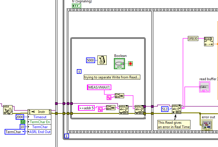
Read a signal scope works in execution to highlight, but not in real time
I want to get the maximum value of a waveform to a former stretch of Agilent 54622 via GPIB.
The problem is that I regularly receive a Visa Read error-1073807339 ("timeout expired before the operation is completed") when running in real time, but NEVER in execution to highlight mode.
The posts here suggests that the calendar can cause the read to run before writing was able to finish. So, I used one - manually controlled while loop, sequence and blocks waiting for try and ultra Structure separated blocks of reading and writing of overlap between them. But it still does not work!
Suggestions, please? (Thanks!)
If you happen to open the VI I attached, you will see that I use a serial port. This is because I use a USB of Prologix-GPIB adapter to interface with the scope (I don't have an adapter USB of NOR-GPIB). I used successfully this Prologix adapter for over 2 years to connect perfectly with an amplifier to locking SR830 and several other devices, so I don't think that's the problem...
What you need is the magic behind fairy!

-
How to build a parser of vector signals PXI using different module combinations
Normal
021
fake
fake
fakePT - BR
X NONE
X NONEMicrosoftInternetExplorer4
/ * Style definitions * /.
table. MsoNormalTable
{mso-style-name: "Table normal";}
MSO-knew-rowband-size: 0;
MSO-knew-colband-size: 0;
MSO-style - noshow:yes;
MSO-style-priority: 99;
MSO-style - qformat:yes;
"mso-style-parent:" ";" "
MSO-padding-alt: 0 cm 0 cm 5.4pt 5.4pt;
MSO-para-margin-top: 0 cm;
MSO-para-margin-right: 0 cm;
MSO-para-margin-bottom: 10.0pt;
MSO-para-margin-left: 0 cm;
line-height: 115%;
MSO-pagination: widow-orphan;
font-size: 11.0pt;
font family: 'Calibri', 'sans-serif ';
MSO-ascii-font-family: Calibri;
MSO-ascii-theme-make: minor-latin;
MSO-hansi-font-family: Calibri;
MSO-hansi-theme-make: minor-latin;
mso-fareast-language: EN-US ;}Normal
021
fake
fake
fakePT - BR
X NONE
X NONEMicrosoftInternetExplorer4
/ * Style definitions * /.
table. MsoNormalTable
{mso-style-name: "Table normal";}
MSO-knew-rowband-size: 0;
MSO-knew-colband-size: 0;
MSO-style - noshow:yes;
MSO-style-priority: 99;
MSO-style - qformat:yes;
"mso-style-parent:" ";" "
MSO-padding-alt: 0 cm 0 cm 5.4pt 5.4pt;
MSO-para-margin-top: 0 cm;
MSO-para-margin-right: 0 cm;
MSO-para-margin-bottom: 10.0pt;
MSO-para-margin-left: 0 cm;
line-height: 115%;
MSO-pagination: widow-orphan;
font-size: 11.0pt;
font family: 'Calibri', 'sans-serif ';
MSO-ascii-font-family: Calibri;
MSO-ascii-theme-make: minor-latin;
MSO-hansi-font-family: Calibri;
MSO-hansi-theme-make: minor-latin;
mso-fareast-language: EN-US ;}I understand
Vector signal analyzers OR consist of 2 or 3 separate PXI modules: 1
digitizer, 1 buck converter of RF frequencies and 1 generator of signals (model 5663).1. can I use digitizer and signal
generator general purpose oscilloscope and generator of signals separately?2 may I build my own VSA by choosing
different combinations of scanners and the signal generators? Or replace the signal
generator by an arbitrary signal generator?3. I
intend to buy a digitizer/oscilloscope and an arbitrary signal generator
analysis of response of frequency on the transformers. Later I plan to
buy a step-down converter frequency and build a vector signal Analyzer. Is this possible?Hello
The frequency IF the 5660 and 5661 (it's the same thing) is 15 MHz, with an instantaneous bandwidth of 20 MHz. The difference between the 5660 and the 5661 is located in the digitizer that accompanies it. The 5660 uses the PXI-5620 digitizer that has a sampling rate 64 MECH. / s and a buck converter of digital frequency limited to 1.25 MHz of bandwidth. The 5661 uses the digitizer PXI-5142, giving you a MECH 100. / s rate and a PSO allowing digital downconversion circuit and the decimation of the full bandwidth of 20 MHz.
The common comment in the SBA above is the RF PXI-5600 frequency step-down converter which is a superheterodyne architecture of three floors. OL is for the three stages of this module are auto-approvisionnées in their own country. The architecture of several step allows for rejection of the improved image and filtering at the expensive of a noise floor slightly higher due to the signal path more complex. There also an OCXO on board, this gives him a time reference more precise - noise reduction phase etc. The PXI-5600 by itself is wide from three locations.
The SMU-5601 since SMU-5663 step-down is designed based on the single frequency step-down converter and resumes from a single location. The celled frequency step-down converter gives you improved noise floor characteristics and a better dynamic range, with the rejection of the image fees, having does not simply because there is only one step. The LO is provided by an external module in this case for several reasons. Have a separate external LO allows more modularity in your system, as well as the ability to share a single LO generator between several vendor-specific attributes. This opens the possibility of MIMO applications. The internal of the NI PXI-5600 LOs are not shareable and therefore cannot be synchronized between several PXI-5600 s. The PXI-5663 (all three modules) takes up the same amount of space in the slot as a single NI PXI-5600 without a digitizer.
The PXI-5154 is indeed a powerful scanner, given its instantaneous bandwidth of 1 GHz. Remember, however, that the connector Active Directory on this digitizer is 8 bits, compared to the 5622 which is 16-bit. If you need more resolution is of course entirely depends on your application. The PXI-5600, as SMU-5601 is controllable as a buck converter stand-alone frequency using the DAMA API OR. You will need to program your application with the scope API for use with PXI-5154 OR and the API de DAMA. A few other caveats to note is that there is no PSO on the PXI-5154 so you can't enjoy the Equalization filter to correct the frequency of the NI PXI-5600 response. Also, as I mentioned above, the frequency of YEW of the NI PXI-5600 has 15 MHz with a bandwidth of 20 MHz - processor 1 GHz bandwidth on your digitizer will be somewhat of an overdose of the IF signal.
While you're dead on with the advantage of modularity, I would take the time to really meet your search application and ensure that different choices of module and their combinations to meet these needs.
Hope that helps!
-
generation of carrier multi using vector signal generators OR
Dear all,
I have a client who asked me about the capacity of the vector signal generators OR to generate signals porters multi, and if yes, what will be the minimum displacement between adjacent channels? There already buy a complete RF PXI system of NEITHER and I need to support as soon as possible
also, if I can work on the 2.7 GHz or 6.6 GHz to test GSM and CDMA2000 1 X RTT units?
can someone help me in this please
I'm in a hurry!
Mohammed,
Since VSGs of NOR are all software based, you can generate practically any signal you want, as long as it is within the bandwidth and dynamic range of the instrument. The SMU-5672 generator has a bandwidth 20 MHz, and the SMU-5673 real-time has 100 MHz of bandwidth of generation. You can create your MULTIPORTEUSE waveform in software and set the way you want.
Each platform is able to test GSM and CDMA2k. I would recommend the platform 6.6 GHz for test times improved if it is for the production. Implementation of the Protocol can be a challenge, however. If you have a great opportunity cell phone, you should get in touch with your field sales engineer OR to see if EITHER can provide any help.
-
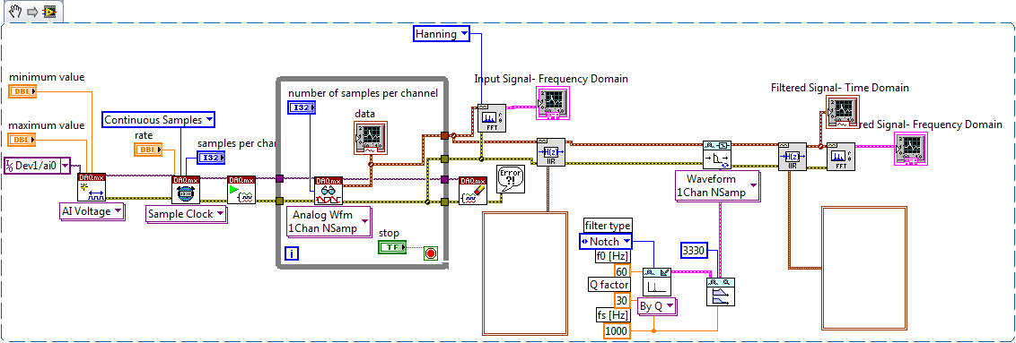
Continuous data acquisition and real-time analysis
Hi all
It is a VI for the continuous acquisition of an ECG signal. As far as I understand that the analog read DAQmx VI must be placed inside a while loop so it can acquire the data permanently, I need perform filtering and analysis of the wave in real time. How I implemented the block schema means that data stays int the while loop, and AFAIK the data will be transferred on through the tunnels of data once the loop ends the execution, it clearly isn't real-time data processing.
The only way I can think to fixing this problem is by placing another loop that covers the screw scene filtering and using some sort of registeing shift to transmit the data in the second while loop. My question is whether or not it would introduce some sort of delay, and weather or not it would be supposed to be the treatment in real time. Wouldn't be better to place all the screws (aquicition and filtering) inside a while loop? or it is a bad programming practice. Other features I need to do is back up the data I na file, but only when the user wants to do.
Any advice would be appreciated.
You have two options:
- A. as you said, you can place the code inside your current while loop to perform the treatment. If you're smart, you won't need to put one another while loop inside your existing (nested loops). But it totally depends on the type of treatment that you do.
- B. create a second parallel loop to perform the treatment. This would be separate processes to ensure that the treatment is not obstacle to your purchase. For more information, see here .
Your choice really depends on the transformation that you plan to perform. If it's much the processor, this could introduce delays as you said.
I would recommend that you start at any place in the first loop and see if your DAQ buffer overruns (you can monitor the rear of the buffer during operation). If so, you should decouple the process in separate loops.
In what concerns or not ' it would be considered as real time processing ' is a trick question. Most of the people on these forums say that your system is NEVER in real time because you're using a desktop PC to perform processing (note: I guess it's the code that runs on a laptop or desktop?). It is not a deterministic systemand your data is already "old" by the time wherever he leaves your DAQ buffer. But the answer to your question really depends on how you define "real time processing". Many lay it will set as the treatment of 'live' data... but what is "actual data"?
-
Control of data using multiple thermocouples via indicators and the waveform in real-time
I apologize in advance for this question is probably a bit simple but I'm all new to labview and the forum and could use some advice. I have a CompaqDAQ with two 9213 16 modules of track and I'm trying to read in 30 thermocouples in a waveform, but also display 30 indicators so I can mark each indicator with the thermocouple for real-time tracking. Each thermocouple corresponds to a specific location and it is essential that the interface has an accurate indication or a label for each of them. I wonder if there is an easy way to do this in addition to split the signal and have 30 thermometers on my diagram? Perhaps a table any? If I use a table to create 30 thermometers, the DAQ assistant automatically sorts the thermocouples according to ascending numerical order. For example, would be the indicators of first and second on my interface automatically assigned to channels a0 and a1 of the first module, or should I do it manually? Even for the waveform? Thank you very much!
PS - Do not know if this message had need of more details, but let me know if more information is needed, and I'll give you!
I see that you use the DAQ Assistant to create your task. Now I understand why you may have about labelling. It is easy of the seller NOR spiel booting... But in any case, you already have a task to the MAX instead of use the DAQ Assistant? The interface is similar and there may be a step or two, but your end application will be more effective and you will have more options with your data and properties. For example, I tried to update the names of physical channel in the DAQ Assistant installation program, that it let you do, but it propagates that change forward to waveform chart legend. Also, I don't know any property for this dynamic data type node, although I never use it either. I suggest the setting up of your task and channels, Max if you'd give it a go.
Since I thought I didn't really takes you all the way with you help, I wrote another one. It uses a cluster, even if it's a bit barbaric. I thought that there was a more eloquent way to do by changing labels, but I could not it works as I had expected.
Maybe you are looking for
-
How can I change the location of the weather on the empty search page?
in the upper left corner of the image is a place of the weather (not my current or even good location... I don't see this when I open a new window empty, and even if this isn't a real big problem I'd want to see the where I am or not show at all.) I
-
Re: Tecra M10 - 1JP - components material
Hello What hardware components are used in this model?W-LAN-Chip?Network embedded?Web - Cam?Hard drive?Perhaps, I drink like too chenge the hard drive. I am looking for compatibility linux for this model. Thank you
-
I open iPhoto and move of my moments. I create an album of my moments and add it to iPhoto events. I then try to remove pictures of moments manually, but then they delete album? So frustrated with this new version of iPhoto!
-
Save failure # (0 x 80070578) Invalid Window Handle
My weekly Windows backup had worked well upward until about 3 weeks ago. Then for reasons beyond my technical know how, I got a backup failure! When I clicked for more details, it gave me error #(0x80070578)-Windows handle invalid. I have a HP Pavili
-
Encryption advice please WRT160N router/gateway/modem wireless
I would like clarification on security and encryption please. I have a WRT160N router/gateway/modem wireless with WPA security is enabled. I have a wired office with LELA installed and a wireless laptop. A key is required when connecting the laptop