AO. MaxRate, AO. MinRate, AO. Properties of voltage. RNGs for hardware DAQ USB-6008
Hello
in one of my report, I use the AO. Property of Voltage.Rngs to see if the selected DAQ card takes in charge the application voltage range. This works very well for my PCMCIA card as well as a PCI card. Now run the same VI with a USB-6008 device, this property gives all the return values. In addition, the report of AO.max.rate and AO.min.rate of the '0', the output is-200197 error properties. I use DAQmx as it is supposed to support the same functions for all DAQmx devices. Can someone please tell me what wrong here and how can I get around this?
Best regards
Gabs
AO.min.rate and AO.max.rate are 0 and error-200197 back because the USB-6008 case supports the outputs analog hardware timed. The description of error is "device does not support this property." There is an entrance to the knowledge base for this question.
By selecting 'Use Waveform' uses the synchronization of the sample clock. The waveform data type specifies a delta t, which is used to set the sample clock frequency. It is not supported on the box USB-6008. You shouldn't set your calendar of sample type or explicitly assign the "On Demand".
The DAQmx driver supports hundreds of different devices. Not all combinations of properties are valid for all devices.
Tags: NI Hardware
Similar Questions
-
DAQ USB-6008 will be able to power and record voltage for UMS T5 blood pressure at the same time?
I would use my NI USB-6008 to power my blood pressure monitor UMS T5 (http://www.ums-muc.de/en/products/tensiometer/t5.html) but also to take readings of it, but I don't know if it's possible to do it properly. The power supply for the instrument can be as low as 5V, I can easily get the dedicated + 5V channel. I'm able to feed the instrument and connect it to an analog input on the 6008 and measure a voltage in differential mode. However, when you read the documentation of support for the instrument, I find the following:
"Potential pitfalls of data acquisition: the pressure transducer is configured in a full Wheatstone bridge, the input voltage and mV signal output can be connected to the same reference (mass)." Therefore, the mV output signal can be measured using a differential voltage measurement. Therefore, do not make an asymmetric measure of pressure transducer mV output. "(http://www.decagon.com/assets/Uploads/MeasuringUMSTensiometerswithnon-UMSControlandDataAcquisitionSystems.pdf)
My understanding is that the 6008 can take a differential measure if I attach the signal '+' and the signal "-" to the analog inputs of positive and negative terminals. However, it seems that all the ports of ground on the 6008 are grounded to the same reference, which would make my measure of invalid tension according to the above paragraph. So my real question is: if I try to record the voltage with one of the analog inputs on the 6008 in this way, is the valid measurement? Or I need to find a separate power supply, with a different reference field to ensure that the measure is accurate?
The technical details of this device is very poor. The manual is not much better. Companies that want to sell scientific equipment should publish decent cards or get out of business.
In section 3.4.3 General requirements the device is described as a "bridge not amplified circuit. This information along with the impedance of the bridge should be in the specifications, because it is essential to apply the device under any circumstances other than the nominal behavior in 10.6 V.
The answer to your question is:
You can use it with the box USB-6008. The 5 V supply will result in output voltages a little less than half (5/10.6) the voltage specified in nominal conditions. You can use the differential input mode on the box USB-6008. The absolute input voltages will be approximately 2.5 V with the 5 V power supply. This voltage is in the range of the aircraft. The differences are likely to be less than 100 mV. The resolution of the USB-6008 on the + /-1 V is located about 0.5 mV so your resolution of pressure will be about 1% of full scale. The voltage input impedance and termination of the USB-6008 will present a few errors. These can be in the order of 5 to 10%. I can't predict much better without the missing bridge impedance specification. These errors should be relatively constant and systematic. A calibration of the whole system - sensor and together hardware DAQ should allow you to compensate for a large part of this error.
Lynn
-
Want a ramp of output voltage over time and measure input 2 analog USB-6008
Hello
I want to produce an analog voltage output signal that increases over time with a certain slope, which I'll send in a potentiostat and at the same time I want to read voltage and current (both are represented by a voltage signal) that I want to open a session and ultimately draw from each other. To do this, I have a DAQ USB-6008 system at my disposal.
Creation of the analogue output with a linear ramp signal I was possible using a while loop and a delay time (see attachment). Important here is that I can put the slope of the linear ramp (for example, 10mV/s) and size level to make a smooth inclement. However when I want to measure an analog input signal he's going poorly.
To reduce noise from the influences I want for example to measure 10 values for example within 0.1 second and he averaged (this gives reading should be equal or faster then the wrong caused by the slope and the linear ramp step size.) Example: a slope of 10 mV/s is set with a 10 step size. Each 0.1 s analog output signal amounts to 1 mV. Then I want to read the analog input in this 0.1 s 10 values)
Because I use a timer to create the linear ramp and the analog input is in the same loop, the delay time also affects the analog input and I get an error every time. Separately, in different VI-programs (analog input and output) they work fine but not combined. I searched this forum to find a way to create the ramp in a different way, but because I'm not an experienced labview user I can't find another way.
To book it now a bit more complicated I said I want to measure 2 input analog (one for the voltage of the potentiostat) signals and one for the current (also represented by a voltage signal) and they should be measured more quickly then the bad of the analog signal. I have not yet started with because I couldn't read on channel work.
I hope someone can help me with this problem
An array of index. You want to index the columns for a single channel.
-
How can I programmatically change the parameters of voltage range in a DAQ Assistant
Hello
First post here.
I need to be able to change the properties of voltage range of a daqmx assistant DAQ based on user input. My material, an SCXI module - 1102C does not change this property on a running task, so I would together the range of input voltage analog before activating the DAQ Assistant, or break the DAQ Assistant immediately after it starts, set the values, and then resume.
I don't know how to change the task ahead because the DAQ assistant creates the task when it is running, and there is no job before that.
In the attached photo, I have a conditional section, configured to run only if the loop iteration is 0. I take the task of the Daq assistant, sending him stop vi of task, set the property and then send the task with the snap the vi task. I can watch him run with lightweight debugging on, and everything seems to work properly, but on the second (and all others) iteration of the loop, I read I. Max and it seems that a re DAQ Assistant set it to the 5V. You can see what's going wrong here?
BTW, there is a continuous acquisition and the code doesn't produce error messages when executing.
I've encountered a similar question someone posted here in 2006, but his question was specifically a Labview API (VB, I think) and not a real solution of G.
Attached are the real vi in question and a PNG of the block diagram.
Thank you!
Ruby K
First of all, if you want to start getting beyond the basics with the DAQ hardware, you have to stop using the DAQ assistant and do it with lower level VI DAQmx. There are hundreds of examples in the finder of the example. You can even make a right-click on the DAQ assistant and select open front panel. This will create a Subvi, you can open and see what is happening behind the scenes. Do it. I think you will find that the task DAQ is recreated on each (although I'm not 100 percent the way parameters are established or maintained in each section of this sub - VI).
The second problem is that you have a bit of a race on iteration 0 condition. These two property DAQ nodes are running at the same time. Thus, when you read the AI. Max, this can happen before or after the AI. Max is located in the structure of your business.
Thirdly, make sure that involve you your son of the error.
-
USB 6008 weird analog voltage reading
Hello
I use the USB-6008 to measure a voltage of a Lithium battery, 3.66V.
the battery come with a blocking diode (in series with the battery) of 1N5820, who have a fall of voltage drop of 0, 1V.
battery with diodes in series (this is the way in which the battery is shipped with)
-measure with DDM yield 3.66V without you connect to usb6008
-measure with DDM yield connected to usb6008 (putting OUT VOLTAGE USB6008) 3.59V
-able with USB-6008 performance 3.59V connected to usb6008
battery with diode removed
-measure with DDM yield 3.66V without you connect to usb6008
-measure with DDM yield connected to usb6008 (putting OUT VOLTAGE USB6008) 3.66V
-able with USB-6008 performance 3.66V connected to usb6008
Thus, it seems that the problem is in the led in the series. This is why the battery voltage has fallen to 0.07V? the series diode will hurt the USB-6008?
Maybe people who know the circuits inside the USB-6008 can give me an answer.
Thanks in advance.
Hi learnerd,.
The fall that you see is falling forward in the diode. As an entry class device, the USB-6008 case has a relatively low input impedance (144kOhm) and thus draws a little current of the device. Looking at the datasheet of the 1N5820 (http://www.onsemi.com/pub_link/Collateral/1N5820-D.PDF), Figure 7 shows that at 25 ° C, a draw of 50mA will cause a fall front of 200mV. While the figure does not extend the curve below 50mA, extrapolating the given curve would indicate that a drop of 70mV would cause only a few current microamperes.
A DMM will have a much greater input impedance (GOhms instead of kohm) and won't draw enough current to influence the measure, that's why you wouldn't see the decline with only the DMM.
The diode will not harm the USB-6008 somehow.
Good luck with your application,
The f
-
Beyond the limits of voltage on USB 6008?
I use a USB-6008 to measure analog differential in the range of 3 to 5.3 V. I chose this range, because outside this range, I'm not interested in what the tension is, knowing that his "on the rail", but to aid resolution of the ADC in this range.
So for a signal of ~0.05 supply V, I expected to read 3V, telling me that the voltage is lower than 3V, but again it returns 0.05v?
As it was unexpected for me, could someone please explain what can / should I expect of my USB6008 of the responsed to the signals that are the limits? Is there an effect of "rollover"? Should you return the value to the limit? Depends on how far the limit is?
Thanks for your help!
Entry level do not think that way. You specify the range is that you wait for the signal and the DAQmx driver will set the most appropriate range that the device supports. The actual ranges are indicated in the guide. In your case, because you specify a max of 5.3, the device would be defined the +/-10 volts range.
-
NEITHER USB 6008 voltage offset using CSR and measurement of diff.
Hi all
I am currently trying the NI USB 6008 housing and I'm getting problems when reading voltage analog using CSR or differential.
So basically, what I want to measure is a PWM signal (0 to 12V), which is divided by a divisor of tension (by two). But instead of measured 0V and 6V
I am in a position a constant 0.8V and approximately 3V.
On the side of digital data acquisition, I give you on impulses for the SSR... and it works fine.
I connect it that way: http://digital.ni.com/public.nsf/allkb/95CC0CB11D7DF3D18625712E000C4ABD?OpenDocument
Would apreciate any help
Best regards
EDIT: Attached graphics acquired are
What is the impedance of your voltage divider? The input of the USB-6008 impedance is not very high. If the impedance of the partition is large, it could cause the effect you see.
Lynn
-
USB-6008 LABVIEW 8.2. SINGLE CHANNEL WITH DBL INPUT VOLTAGE OUTPUT COMPARISON
I AM WRITING A PROGRAM THAT USES A SIMPLE USB-6008 ANALOG INPUT CHANNEL. I WANT TO READ CONTINUOUSLY THE VOLTAGE FOR 60 SECONDS. I WANT TO COMPARE A TENSION FOR THE PREVIOUS OF THIS SAME CHANNEL VOLTAGE, MAINLY FOR THE PERIOD OF TIME MAX VOLTAGE GIVEN, THEN GET A FINAL VOLTAGE READING. THE OUTPUT OF THE VI IS A DBL. I WANT ONLY TWO TENSIONS OF EXPORT TO EXCEL. TO SAVE TIME, I KNOW HOW TO EXPORT. CAN SOMEONE HELP ME WITH THIS ONE.
VI needs an register shift related to the Max & Min function. The current value would be the entrance is and the entrance of x is the left shift register. The max value gets wired for the shift register to the right. Don't forget to initialize it. The output of the shift register is the max you would write and the value of the DAQmx Read out of the loop of wire will give you the last reading.
Your waiting for 45 seconds makes no sense since you said that you wanted to read continuously. You also said that you wanted to read 60 seconds and all this logic is missing. A simple function of time elapsed, it's all you need.
-
NEITHER USB-6008 can measure an AC voltage
Now I am doing a project, but don't know if DAQ can measure an AC voltage or not, the acquisition of data that we use is USB-6008.
Yes, it can measure AC in the range of +/-10 volts and have a sampling rate of 10kS/s.
Application engineer OR
-
Measurement of voltage USB 6008 ranging from 1mV
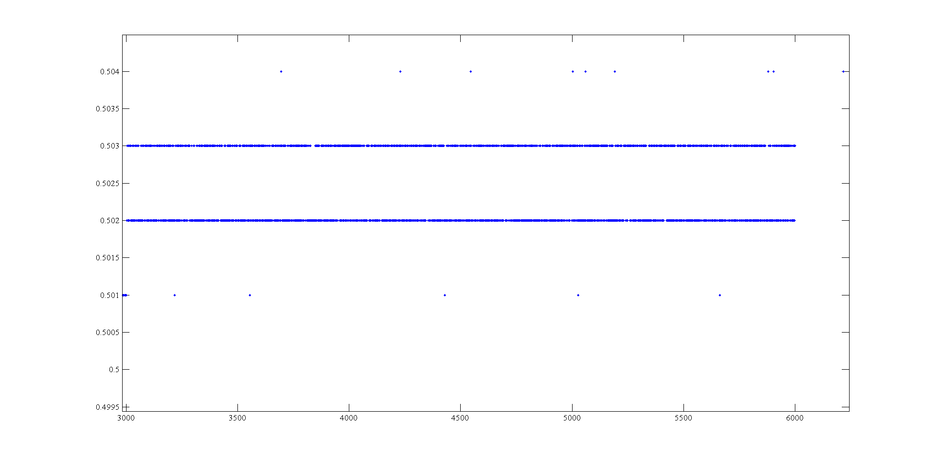
Hi, I'm doing a supply at an angle for an amplifier using the USB-6008. The ranges I look are - 0.5 to 0.5 V and 0.5 to 2.5 V. To generate negative tensions, I use the + 2, 5V for a reading of differential voltage output as a 'ground '. Voltage measures have a delay that varies with the voltage, given this by drawing these variations and set the output to data acquisition there is still a 'noise' of +/-1 mv so that it is clear from this parcel of tension against the sample number:
It seems that at some point the values are being rounded up to the nearest millivolt. I need to get to a resolution of 0.5 mV for my device, it will be possible with the USB-6008?
The AO USB-600 x has a range from 0 to + 5 V and the 12-bit resolution. 5/4096 = 1.22 mV. Absolute precision is 7 mV typical and 36.4 mV maximum full scale. The noise of the AO is not specified.
If you measure the results with THE USB-6008, you have at least 0.5 mV, similar resolution system noise and absolute accuracy of 2.5 mV or more.
It's probably as good as you will get with the box USB-6008.
Lynn
-
Voltage Excitation for IEPE/ICP and IOTech 650U
Hi all
I am using IOTech DAQ 650U (OR product no. 781277-01) with ICP/IEPE accelerometer. It works very well with accelerometers of general purpose PCB/IMI (IMI 607 A 11 model example). We want to use seismic accelerometers and wonder if IOtech 650U can collect data from seismic sensors (example - IMI 626 A 04 model). Most of the electrical specifications of the two sensors are similar (2-20 my constant current), except that the voltage is more versatile (18-28 VDC) for seismic sensor (24-28 VDC). -What it means and means of IOTech 650U does not work with seismic sensor? I don't think, but I'm not sure. I tried to read about this subject and found NO article on voltage is lower than the voltage of compliance (http://digital.ni.com/public.nsf/allkb/3CEFD95B14604C7386257598006C6233).
However, I couldn't find the conformity of IOTech 650U voltage specifications. Any help in this regard is highly appreciated. I want to know if we can use the accelerometer seismic (IMI 626 A 04) with IOTech 650U or not? Thank you.Usually you want to measure low or very low frequencies with seismic sensors.
So check to see if the high passes of frequency of your data acquisition fits your needs.
A lot more low power low voltage will only limit max amplitude can be measured...
-
Voltage change of reference (PGA) of NI USB 6008 in Matl
Hello
I'm looking for the solution change the voltage reference usb6008 nor in MATLAB.
Referring to the manual, the reference voltage can be changed by setting the PGA (programmable gain amplifier). There is a brief description in the manual, which can't help me ("The PGA gainis automatically calculated according to the voltage selected in the application range of the measure.)
Does anyone know how can I change the PGA in MATLAB?
Input voltage range is set to [10-10] and I want to change it to [1-1] to get a better resolution for small voltage. The InputType is differential
Hi Kia
You can change the reference voltage by adding following function in your C code:
Int32 DAQmxCreateAIVoltageChan (TaskHandle taskHandle, const char physicalChannel [], const char nameToAssignToChannel [], int32 terminalConfig, float64 minVal, maxVal, int32 units, const char customScaleName [] float64);
With the minVal and maxVal settings, you can manually set your tension.
Of course, I am available for more reminders.
Best regards
Stefan
-
Voltage conversion for the Module e/s-OR-5751
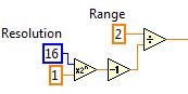
The only place where I can see an example of this is the example 'NOR 5751 finished several acquisition channels'. The conversion to the VI is illustrated below:
It is a 14-bit digitizer, so I'm not the "16" for the resolution.
The text in the example says: "data from the 14-bit a/d converters are represented in the CLIP as compliment of 2, MSB justified, I16.". 2 LSBs are filled with zeros. The data are multiplied by a scale factor (ADC voltage resolution = voltage range / ADC * 16 intervals) to LSB justified data and scale to volts. "This seems to be different from the code above.
I don't understand what is the factor of 16 text. Or I do not understand how they are the same.
Hey JP82,
The 5751 is one of our familiarization trips that produces data MSB justified, with even two most (LSB) containing 0.
If you changed the generetaed of data by the fam to the right by two, then you must use 14 bits resolution.
Example of MSB justified:
Input voltage: 1V
Binary representation of FAM: 0111111111111100Sign bit ^ zero of the LSB ^ ^
Decimal Rep: 32764
MATH:
2 / (2 ^16 - 1) * 32764 =
3.05E - 5 * 32764 = 0.999302 ~ 1V
If he was justified in LSB:
Input voltage: 1V
Binary representation of FAM: 0001111111111111Sign bit. ^
Decimal Rep: 8191
MATH:
2 / (2 ^14 - 1) * 8 191 =
1.22E - 4 * 8191 = 0.99993 ~ 1V
I do not believe that data are two is completed, as indicated in the details. I'll see that this gets fixed.
-
Using the DAQ USB-6009 meter and an analog input voltage at the same time.
Hello
Currently, I'm reading the two channels of voltage with the USB-6009. It happens that one of the channels is the output of a digital coder, and it would be much easier to use it directly to the PFIO entry that is defined as a counter. The problem I am facing right now, it's that I can't use the DAQ Assistant to use the analog voltage to a channel and the digital channel counter at the same time. Once I put the DAQ Assistant to read the input from analogue voltage, I won't be able to add analog inputs. And as I put the DAQ Assistant to use the PFIO as a counter, I can add more entries to read analog voltage is.
I wonder if it is possible to solve this problem using the lower level data blocks? Another solution would be to read two channels in analog input voltage and that the use of Matlab to process data resulting from it, since I was not able to do the counting to work simultaneously with the acquisition in Labview to impulses.
Hope you guys can help out me.
Thanks in advance.
Using a simple wizard of DAQ is incorrect. You need one to acquire analog inputs and one for the meter.
-
Measures of true bipolar voltage with USB 6008/6009
The 6008 or 6009 to make true bipolar (positive and negative voltages referenced to GND) measurements? If not, what is the solution to purchase cheaper data this feature?
Thank you.
The question of unipolar vs bipolar vs bipolar Pseudo-aleatoire also was mentioned in this thread. The 6008 6009 use bipolar-only mode and load the setting differential input or CSR. Please note that {unipolar / bipolar / Pseudo-bipolaire} is independent of {differential / CSR / Pseudo-differentiel}.
The 6008/6009 don't use 'Pseudo-bipolaire', which means that each differential input should be positive with respect to the ground.
Best regards
Maybe you are looking for
-
Evry time I open a new tab, I want google search to be here, hoe do
When I start a new tab, I would like the page to search google, currently all new tabs are blank pages...
-
I am trying to copy a letter from my affiliate page and place copy in my answering machine, but he said that firefox will not allow this. If I can't fix to day I have to go back to Internet Explore.Thank you, Pam
-
How to get to the issues section of this Web site?
Hello This site is really twisting my mind: I posted a question a while ago and there is no way to come back because my dashboard is empty and there is no apparent connection with the questions of this Web site section. Thanks to Google, I slipped my
-
Satellite Pro A30 with BIOS not fully ACPI compatible for VISTA
I would use my beloved sitting Pro A30 to dual boot with Windows XP Home edition and Vista but having bought a 80 gig HARD drive and would divide in 2 partitions, I have now WXP SP2 running on the first partition, but try to install vista on the seco
-
Hi all. I just installed windows XP Pro on one of my computers. Now when installing, it showed me the main partition C and another extended partition (which was very small). Now windows gave me the option to install Windows on the C partition and it