application of current-voltage output of a sensor output
HIII... my question is that we have two types of sensor output. one is currently & other is under tension. can anyone specify that is the specific application where we use a sensor with current output only & in what application, we use a sensor whose only output voltage?
Pls answer soon...
In a noisy electrical environment the current drive for the signal is less inclined to pick up noise from a signal voltage level, as RF has pointed out the 4-20mA signal is useful for troubleshooting when a wire is disconnected - Mike
Tags: NI Software
Similar Questions
-
Hello guys,.
I have a general question regarding the units of packaging such as the USB-9263 analog output signal. If I can use it instead of data acquisition to provide an analog voltage output?
Thank you
ELA
Yes, the 9263 can provide 4 output channels analog voltage (+/-10 v range) with up to 1mA of current drive. Looks like: it refers to the short circuit of conditioning of signals and some protection against overvoltage. Link below is the User Guide:
http://www.NI.com/PDF/manuals/372406b.PDF
-AK2DM
-
Hi, I have an iMac 27 "(mfg mid-2010) bought in Singapore." I travel in North America. The computer is still in good condition and want to know if I can take it. For most electronic devices, the different current/voltage in North America that makes them more or less useless, but laptops, for example, have the adaptability between the two parameters of current/voltage. The iMac has this capacity? The food fits North American power?
Yes, he does.
(142107)
-
HP scanning application is currently in use or unavailable
= HP C7180 printer
OS = Windows 7 (64-bit)
When you use the solution Center to analyze, an error window opens, saying:
"HP scanning application is currently in use or unavailable"
What to do?
Hi skinman88,
Download and run the (print and Scan Doctor) from the link below. I would like to know what are the errors you receive?
-
acquire the voltage output of a channel of analog output current
I'm controlling a HV configuration rather sensitive analog output voltages. Is there an easy way to read the voltage level which is currently awarded by an analog output?
Hello
If you set your subVIs different voltages, you can be sure that the voltage you set in these screws are similar to tensions, you have to your output PIN. For example, you could write the value you give to the output in a variable and read this variable in you main VI.
Kind regards
Peter
-
read the output of a path of analog output current voltage
In DAQmx if you are unsure of the status of a digital output port, you can take a reading on this subject. When I try this on an analog output, I get an error. Is it possible to query the status of the output of an analog output? I realize that I could follow the State with a variable, but a direct reading would be really handy.
Hello, GIS.
There is no way to read the output in the AO modules without wiring physically the signal to a module to HAVE. You are able to use a variable to read the current value of the output, as you mentioned earlier.
Channels AO multifunction boards, however, can be read through tasks of entry by rounting in-house channel to read ao vs aoground.
Lisa
-
USB-6008 LABVIEW 8.2. SINGLE CHANNEL WITH DBL INPUT VOLTAGE OUTPUT COMPARISON
I AM WRITING A PROGRAM THAT USES A SIMPLE USB-6008 ANALOG INPUT CHANNEL. I WANT TO READ CONTINUOUSLY THE VOLTAGE FOR 60 SECONDS. I WANT TO COMPARE A TENSION FOR THE PREVIOUS OF THIS SAME CHANNEL VOLTAGE, MAINLY FOR THE PERIOD OF TIME MAX VOLTAGE GIVEN, THEN GET A FINAL VOLTAGE READING. THE OUTPUT OF THE VI IS A DBL. I WANT ONLY TWO TENSIONS OF EXPORT TO EXCEL. TO SAVE TIME, I KNOW HOW TO EXPORT. CAN SOMEONE HELP ME WITH THIS ONE.
VI needs an register shift related to the Max & Min function. The current value would be the entrance is and the entrance of x is the left shift register. The max value gets wired for the shift register to the right. Don't forget to initialize it. The output of the shift register is the max you would write and the value of the DAQmx Read out of the loop of wire will give you the last reading.
Your waiting for 45 seconds makes no sense since you said that you wanted to read continuously. You also said that you wanted to read 60 seconds and all this logic is missing. A simple function of time elapsed, it's all you need.
-
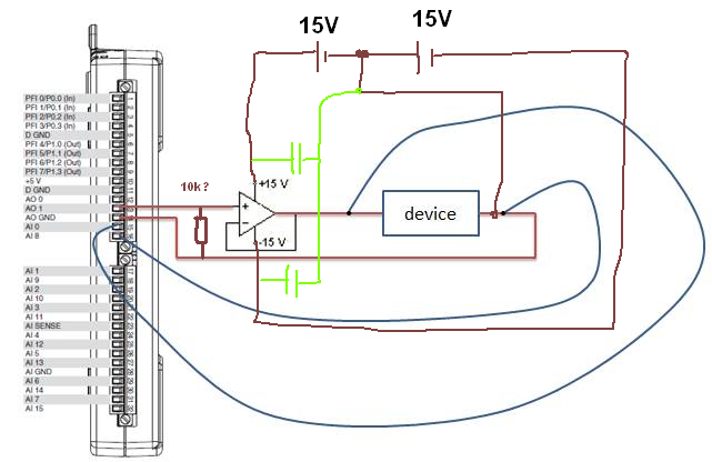
How of current analog output more than 2mA
Hi, I have designed a simple PID loop to control the input of a device voltage. My camera has an Ohm resistance. I found that being controlled input voltage may not exceed 0.6V, then I realized that the maximum output current is my 6211 NI DAQ 2mA. But I really need more 2mA (Max is 10mA). I tried to use a voltage follower because it has high impedance imput and low output impedance, but it does not work. Could someone tell me a method to solve the problem?
Thank you.
CJL
100nF caps | with 10µF,.
R optional...
What OP do you currently use?
Without this connection GND current can flow
 so you will stick to 0.6V as without a driver.
 -
Send the signal current/voltage/USB DB25 to regulation of pump to
Hi all!
I want to control the speed of a pump with LabVIEW (Thermo Fischer FH100M, Manual) and so I have to send a current or a voltage signal to the pump. The pump has only one DB25 port. As my laptop is not a port DB25, I tried to control it with a USB converter.
I had only a converter USB to DB9, so I started with (laptop) USB-DB9-DB25 (pump) > >.
When I connect the pump on the USB port, it is instantly put in market, but in a strange way.
Is it possible to use this configuration? Or is it possible to use at least USB-> DB25 (I have the Setup, see manual page 45/3-19)? Then, I would order that the cable companies.
Or do you have other suggestions?
Thank you very much in advance!
Tobi
Tobi,
Stop it! Do not connect your converter to this device.
When you say "Converter USB to DB9" are you referring to a USB converter to RS - 232? DB9 is just a connector and therefore DB25. TOU can wire anything to this connector. Your converter is probably wired as a serial RS-232 port.
The manual shows clearly on page 3-19 and the following pages that the control of the pump is NOT wired for RS - 232! By looking at the speicifications for the inputs and outputs you shown on page 3-20 and 21 may damage the USB to RS-232 conveter or the controller of the pump by connecting them.
To control this device you will need to a DAQ with analog input, analog output, material inputs digital, digital, outputs a counter. You will also need some external circuits such as transistors or relay static solod DC in proportion.
Lynn
-
Fastest time expected update - NI 9265 current of output
I use an output module current 9265 with 9174 chassis. Basically, I want to read in a text file, analyze a value to a certain dt (at the present time, I am 20 Hz) and writing a value to the card, which will control a valve. Break down: adjustment points (1) read a 4-20ma 2) output the value of EI file to a certain dt for each iteration in the while loop. Can I expect this system to be close to 20 Hz? I need my timing to be very close, but I understand that by using a Windows system (Windows 7) will cause the jitter in the system and avoiding the near-perfect. Thank you.
Hello Mr._Bass,
The NI 9265 updates its output values each 9.5 US, that only calculates over 100,000 samples per second. Therefore, the hardware itself has the ability to maintain this speed. Depending on your system and the amount expected from the jig, this number can vary quite a bit depending on your machine. If you have typical tasks such as antivirus, firewall, or any other thing that Windows is running in the background, jitter will increase. On average, the amount of jitter in a windows system is the order of the hundred nanoseconds, but can vary considerably. Outputs at 20 Hz will be an update with a period of 50 000 (0.05 s), so even if your system jitter is high and about 50 US, it would affect only your calendar of 0.1%. Please keep in mind that these amounts of jitter are estimates and may be not accurate for your system.
If your application must be very closely controlled, and you see higher levels of jitter that your system can support, there are steps to take to reduce jitter. The best way is to use LabVIEW Real-time, but this option would probably a bit of review to implement. I recommend just using a timed in LabVIEW for Windows hardware output operation. Because the jitter occurs in the operating system, you can write your data to the physical buffer of your NOR-9265, where the sample clock will have no interference of Windows. "To see the difference in hardware and software timed operation, launch the Finder for example OR by browsing in LabVIEW for Help" find examples. "" "Then select hardware entry and exit" DAQmx "analog generation ' current. You can see two examples, Gen Mult current updates-Int clock VI and Gen Mult current updates-SW Timed VI. The main difference between these two screws is the use of the VI DAQmx Timing for timing of setting material being controlled. More information on the implementation of operations of timed material are available here: http://www.ni.com/white-paper/2835/en#toc5
I hope you find this information useful. If you are concerned with the jig in your system and need an easy way to measure and control, you might also look at using the NI LabVIEW Jitter analysis tools. Good luck with your application.
Concerning
-
Card bad voltage outputs data acquisition / cut off voltage
Hello
I use a 6713 PCI and PCI MIO 16E1 and have a very strange problem: when I try out a voltage using LabView, I get instead of the voltage, a tension cut with a high unstable phase. Basically, all right, as long as my blood pressure is below 0.3V. All is well here, high level is stable, precise curve shape. But as soon as it exceeds 0.3 V, it is cut and the tension starts to drift. I have attached a drawing of the problem in this post.
The system worked very well, but a week ago, the problem appeared. First he went again, but now he reappeared. The first attempt to define a certain tension might work, but already for the next pulse the problem occurs. Now she even work correctly once. Reboot etc did not help.
The funny thing is, however, the same PC has two features listed above. I only and never used the PCI6713. When the problem occurred, I tried to move to the MIO 16E1 but it shows the same thing! Exactly the same problem here! I unplugged all the wires to the cards and it still does not work. Anyone here with an advisor?
Thank you!
Mike
I was able the output voltage with a scope with 1 MOhm input impedance. But I found the problem by chance now! We got a whole batch of defective cables BNC! I already suspected the cable and tried different cables, about the same result. Then somehow, as I wrote, the problem disappeared once. Now, I used another type of cable to test the unit and it worked! So I checked the other BNC cables, and some of them seem to have a shortage between the mass and the Center, but in a way it produces sort of a junction diode (probably because of a layer of oxide somewhere). When I shook the cable suddenly I could measure a low impedance between the mass and the Center, but only for milliseconds, just like a bad contact.
Really weired! But thanks for the help!
-
Update of unique value in the loop voltage output?
Hello
I'm trying to use the DAQmxWriteAnalogScalarF64 function to produce a voltage constant and regular say 3V. The program will be in a loop, and after each iteration, I would that the output voltage be increased to say 0.1V.
So, a shortened version of my program looks like this
float64 value = 3;
DAQmxCreateTask
DAQmxCreateVoltageChan
DAQmxWriteAnalogScalarF64 (TaskHandle taskHandle, bool32 autoStart, float64, float64 value, timeout, bool32 * reserved);
Loop
{
DAQmxStartTask
DAQmxStopTask
}
Now of course who does not help me update the output voltage after each loop. So I tried something like this:
Loop
{
DAQmxWriteAnalogScalarF64 (TaskHandle taskHandle, bool32 autoStart, float64, float64 value, timeout, bool32 * reserved);
DAQmxStartTask
DAQmxStopTask
value = value + 0.1;
}
My computer would crash when I try to run the program. I have to erase and create the task in each iteration too?
I try to avoid using the DAQmxWriteAnalogF64 function, because I need to use a sample clock in time, he and my sample clock is used for the other channel of analog output.
Thanks for any input.
Howard
aNItaB,
I tried to call the DAQmxWriteAnalogScalarF64 in a loop and freeze my computer completely and I have to restart it by pressing the Start button.
Then, I tried to use the DAQmxWriteAnalogF64 in a loop, specifying the output as an array of one element array, and then to update an element at the beginning of each loop. This seemed to have solved my problem for now without any computer breaks down.
A strange thing happened was when I took your suggestion and took the StartTask and StopTask out of the loop, the computer crash problem appeared again.
in any case, I think that my problem has been resolved, thank you very much for your responses timely and sincere help.
Howard
-
Is there no way to run an AIR application audio to audio output devices different from?
I need to do a couple of our AIR applications select some audio devices to send their audio output, and last year, someone mentioned possibly using native extensions to do this. I had to start working on other things for a while, but I'll be back to that (for the moment), and I basically learned how to create native extensions.
But so far, they do not seem to provide me with any privileged access to what's happening under the hood of an AIR application. When you stream live in via RTMP or RTMFP, details of the audio you are hidden. It doesn't seem to be any place where you can actually access the audio bytes are sent on the network. You can specify a certain object SoundTransform for the NetStream to use, but this class is final and one vanilla Flash build, so even though she may have a way to access the audio bytes, they are not accessible to all.
It really seems that, when a NetStream starts streaming live audio, there is no way under the Sun for access to the bytes of audio and direct them to a certain audio output device, with or without extensions. Is it so? It would be unfortunate that Adobe does not allow it, even through the native extensions. Thank you.
Couple quick thoughts...
The limits are important. There is a lot of work to maintain a clear separation between a decision to users and developers. For example, you cannot change an audio by default to users out because that clearly violates a decision to users. That said, this is a mess of people debating the issue and in fact finally a COM API without papers you can find allows you to actually do in Vista/Win7 (but not 8), but do not expect that it is a "right thing to do":
You can get a drink before reading this.
Incidentally, RTMP is secure, which explains why you can't access the bytes. The entire purpose of this is to ensure that their media cannot easily be copied or stolen media developers. Adobe don't document their method of securing the flow, but they do not publish the RTMP protocol specification. It is quite possible for you to create your own server method and encryption protocol RTMP while providing an RTMP stream to the custom client that you yourself the code which peut read flow. Here are the specs:
http://www.Adobe.com/devnet/RTMP.html
So I would say that it would be unfortunate if Adobe did give, you access the bytes. You might as well hand users an mp3 of a song because they steal left and right media.
That does mean that you can not use a multitude of ways to get data via the default output device. Many applications (fraps/etc) captures audio streams video and mixed. But Adobe won't give you the keys of the Kingdom and allow you to decrypt protected multimedia Protocol.
-
How to know which applications are currently installed in blackberry
I have a gap of phone that allows the user to enter contact information (including credit card information). Once the details are entered, it should show a page that has the link for all installed applications for blackberry. Is it possible to know what applications are installed in blackberry. Can you please let me know how to go about it.
You can query the system for applications that support specific features. In this list, you can then call the application that allows you to select the user by using the returned object.
https://developer.BlackBerry.com/HTML5/APIs/BlackBerry.Invoke.html#.query
-
Application of current Transactions bills AP
Hello
I'm working on a project of implementation of 11i to R12. We are using a DB link and working on conversions. I am new to Oracle Applications and would appreciate if I can get a query for AP open invoices.
Thank you!
BillaSalvation;
In addition to Hussein snoussi great post , please see:
http://Oracle.ITtoolbox.com/groups/technical-functional/Oracle-Apps-l/Oracle-Apps-R12-open-AP-invoices-query-3308597
List of bills open APRespect of
HELIOS
Maybe you are looking for
-
Don't know what to write.
-
Questions to THE El Capitan fixed yet 2016?
Is anyone know if validation in Logic Pro X is resolved for all the current versions of * contact * play 4 East West * sampltank in El Capitan 11.3 yet? IMac 13.1 2.9 16 GB 1 Yosemite 10.5
-
Hi all I bought a TV series on iTunes, and it has been suggested that I have to keep a copy of it on my computer 'because the content provider can chose to remove their programming on the iTunes Store at any time, given that the content belongs to th
-
Dv6 - Possible update video card envy?
I searched a bit, and I realize that it is probably the best place to ask. I have a beautiful laptop dv6 of HP ENVY with a NVidia GeForce 650 M GPU, and I'm looking into the possible upgrade. Since there is a GPU integrated as well as a secondary GPU
-
Windows vista Business OEM key product
Hello everyone I'm starting to rebuild a computer acer laptop, I already have an OEM windows vista business CD I was wondering if there is a way to buy windows vista business product key without having to buy a new drive, I don't want to use crack to