Application of voltage E310DW
I bought an E310DW laser printer in the United States. Will it work on the 230 volts in India? Wouldn't be possible/safe to use with a voltage converter? Please let me know as soon as possible because I'm leaving for the India in the coming days.
Thank you.
Mbarya, the American model will not work in India as power to the printer is not bitensión. You can use a voltage transformer but don't guarantee that the power rating is correct. I would say that the transformer is rated at least 25% higher than the power of the printer. I hope this helps.
Tags: Dell Peripherals
Similar Questions
-
What is the best way to change this program and to read 1 sample of each channel?
The initial program was conducted with NOR-traditional DAQ. I change it to DAQmx the best I could. The program, he is already the application of voltage to generate code (Daqmx Write.vi). But I have problems with the acquisition of tensions, give me readings rare (Daqmx Read.vi) I don't know if I have to make a (Daqmx start Task.vi) for each channel in the program or if I can make it work with a single. Notice I have no significant changes a lot because this program is already running in another lab, and they send us the program so we had no problems so much but rather than get the BNC-2090, they got the BNC-2090 is who uses DAQmx instead of the traditional. If anyone can help?
A BNC-2090 is just a connection block. It has no effect on the question of whether you should use traditional DAQ or DAQmx. Which is determined by the DAQ card that you are connected to the terminal block too.
You can refer to this document, differences between the BNC-2090 and connector BNC-2090 blocks has, but it's just saying to change the label of the Terminal Board to reflect the new DAQ cards.
What problems are you having with the new VI you just posted? You get an erro rmessage? I don't know what mean "rare readings.
You really shoud look at some cases DAQmx in the finder of the example. Some problems that you are experiencing, is that your blocks of data acquisition are all kinds of disconnected. Generally, you should connect the purple wire from your work function of creation, through the beginning, reading or writing, then the narrow task. Many of your data acquisition functions are sitting there on the small islands now. You should also connect to your son for the error.
With DAQmx, you should be combining all your analogue channels in a single task. It should resemble Dev0/AI0... AI7. Then use a sample of channel 1 N DAQmx read to get an array of the readings, you can then use array of index to break.
Other things you need to do is to replace the structures sequence stacked with flat sequence structures. Turn on automatic growth for some of your structures such as loops. At the end of the day, you might find, you can eliminate some of the structures of the sequence.
-
PM3000a: Serial Read and Write out of sync
Hello
I'm reading the values of the PM3000a during the series. I use LabView 2009 32 bit and VISA 5.2.
I used the LabView driver and programs downloaded from here and have reworked to get my current VI.
Mainly in my program, I am looping through some series of an array of strings controls and burning one at a time to the PM3000a during the series and then read and store the query results in a digital picture.
For some reason, sometimes values blend. I have attached my VI and a screenshot.
The results that I expect are:
(Power application): FND:CH1:WAT? = ~ 300
(Application of voltage): FND:CH1:VLT? = ~ 230
But the actual results I get:
(Power application): FND:CH1:WAT? = ~ 230
(Application of voltage): FND:CH1:VLT? = ~ 300
Thanks in advance

In somne point you miss read data, so it will stay in the buffer and will be read instead of the most recent data.
Add a ' VISA RAS I/O buffer "before sending a request should help.
And try to find out why there is some left in the buffer data
 data sometimes can be send because of the interaction of the user on the intrument Panel (print button etc.))
The response of an instrument generally includes the unit, using "Analysis of the chain", you can add a control.
During the validation of the screws, you must include the Subvi
For assistance with additional string testing also store strings in an indicator of the chain, make all default values, save the vi and that post.
-
In Labview 8.6 and MAX, I can change a scale for a voltage read the string in a task once the application has been built and installed on a second PC. Where's the info of the scale which is held?
Hello
Once you have built your VI and compiled into an executable file and deployed on another machine, it essentially becomes a file read-only, which means that you will not be able to change the balance in this deployed application.
Kind regards
Marcus
-
application of current-voltage output of a sensor output
HIII... my question is that we have two types of sensor output. one is currently & other is under tension. can anyone specify that is the specific application where we use a sensor with current output only & in what application, we use a sensor whose only output voltage?
Pls answer soon...
In a noisy electrical environment the current drive for the signal is less inclined to pick up noise from a signal voltage level, as RF has pointed out the 4-20mA signal is useful for troubleshooting when a wire is disconnected - Mike
-
I'm unable to receive mail via IMAP Apple iCloud. I receive my messages from the iCloud online server, but the mail doesn't come to my Mail application. I have several other accounts who work. Activity monitor shows one CPU % usage large amount of the Mail application. Then he made me force leave because he was using all my App memory. The mail app tried to download the messages that I can see on the activity monitor, but it freezes and will not download. I entered into System Preferences and turned mail/off voltage. I have tried everything I know not how. Any help?
Now my memory of the application in memory pressure is so high, I had to force it give up twice.
-
False values of voltage using NI 9225 and ELectrical Power Suite 2014
Hi all
I have a few problems regarding the use of a map of analog voltage NI 9225 with code exaple quality Applications of power (cRIO) (Delta-Sigma) of the Electrical Power after 2014. Running the example code I values of voltage wrong, they are exactly doubled! For exaple with a 230 V RMS input I get 460 V RMS. I think the problem is the module, because by default, the code example expects to use a module NI 9242. Before the upgrade to LabView 2014, everything worked perfectly with EPS 2013. Am I something missung? I configured the C module in the project manager in the same way that I used with EPS 2013. Can someone help me? Thank you
Gianluca
Hi Gianluca,
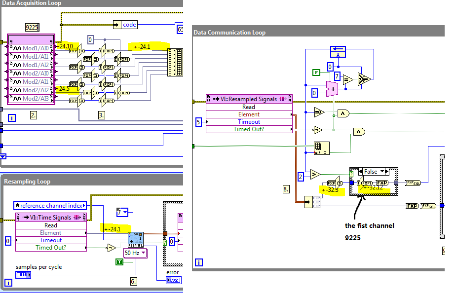
If you use other types of modules in the example, you must take care of the conversion of accuracy in the FPGA VI.
As FPGA VI resampling takes the signal of type fixed point +-24.1, you convert the +-24,10 and-24,5 to 24.1 in the Data Acquisition loop before feeding to the FPGA VI resampling.
And in the loop of data Communication, you restore the output of +-32,3 to 32,12 - signal + and +-32.7. Notice at the time the zoom in and zoom out are equal.
If you change other types of modules of different precision, you must change the precision of the given thread.
For example, 9244 accuracy is +-24.11, so when you convert it to +-24.1, you must restore it by variation of-32,3 to-32,13.
Please refer to the screenshot:
-
Measure the voltage of strain gauge
I have connected my 9237 to a 9945. I use a 350 ohm strain gauge. I have the voltage set to 2, 5V Max is there a way to measure physically to be sure that it is 2.5V? Also, in my vi I use a DAQmx create function of the channel. I want to add another channel for this but can't see how to do it.
Thank you
HS
Hi, Harry, it's Paul with engineering Applications to the OR.
My first question is why you are wanting to physically measure the voltage?
If you are wondering how that tension may vary, it is limited by the maximum capacity of 150mW of your device, as explained here: http://digital.ni.com/public.nsf/allkb/7CBC67482CC9FB318625758C0048FF73?OpenDocument
If you want to continue to measure externally, you have a few options. You can use another DAQ hardware to measure the voltage, or you can use another external device, like a digital multimeter.
If you want to see in the excitement that is actually supplied LabVIEW code, you can use the node property DAQmx 'Value of real excitement'.
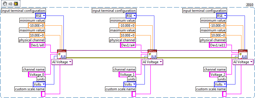
As far as playback of multiple channels, theres two ways you can go about it. If your channels are sequential and all have the same settings, then you can change your name of the physical channel to something like 'Dev1/ai0' to ' Dev1 / ai0:3: to specify the first 4 channels.» Alternatively, if you wanted to select non sequential channels, you can chain create channel set tasks, as long as they are of the same type of task (AI voltage, etc.) and the same device, as shown below.
Let us know if you have any other questions.
Kind regards
Paul
-
USB 6008 weird analog voltage reading
Hello
I use the USB-6008 to measure a voltage of a Lithium battery, 3.66V.
the battery come with a blocking diode (in series with the battery) of 1N5820, who have a fall of voltage drop of 0, 1V.
battery with diodes in series (this is the way in which the battery is shipped with)
-measure with DDM yield 3.66V without you connect to usb6008
-measure with DDM yield connected to usb6008 (putting OUT VOLTAGE USB6008) 3.59V
-able with USB-6008 performance 3.59V connected to usb6008
battery with diode removed
-measure with DDM yield 3.66V without you connect to usb6008
-measure with DDM yield connected to usb6008 (putting OUT VOLTAGE USB6008) 3.66V
-able with USB-6008 performance 3.66V connected to usb6008
Thus, it seems that the problem is in the led in the series. This is why the battery voltage has fallen to 0.07V? the series diode will hurt the USB-6008?
Maybe people who know the circuits inside the USB-6008 can give me an answer.
Thanks in advance.
Hi learnerd,.
The fall that you see is falling forward in the diode. As an entry class device, the USB-6008 case has a relatively low input impedance (144kOhm) and thus draws a little current of the device. Looking at the datasheet of the 1N5820 (http://www.onsemi.com/pub_link/Collateral/1N5820-D.PDF), Figure 7 shows that at 25 ° C, a draw of 50mA will cause a fall front of 200mV. While the figure does not extend the curve below 50mA, extrapolating the given curve would indicate that a drop of 70mV would cause only a few current microamperes.
A DMM will have a much greater input impedance (GOhms instead of kohm) and won't draw enough current to influence the measure, that's why you wouldn't see the decline with only the DMM.
The diode will not harm the USB-6008 somehow.
Good luck with your application,
The f
-
Measurement of current and voltage USB-4065
I have an application where I need to measure the direct current and the voltage. The current and voltage will be stable if the measures do not need to be simultaneous. I would use a USB-4065 to the two measures. I've seen the kb indicating the voltage inputs must be disconnected when the measurement current. The current inputs must be separated for a measure of tension?
Hi Collin,
I think that you are referencing this knowledge base. After a few tests, and worked with the R & D group, it seems that the effects of input connections are perceived during the passage of two ways. When the current entries are connected, a less accurate voltage reading occurs. As such, please disconnect the current inputs for a measure of tension (as well as disconnect with tension when taking a measurement of current entries, who you know).
-
Complete noob - would like to measure the voltage to manual start and stop
Hello
As the topic says I'm a complete noob when it comes to programming OR.
I'm looking for someone to point me in the right direction
Installation program:
Windows8 office
Visual Studio 2013
NI 6255 PCI data acquisition card
Block connection OR SCB-68
What I want to do:
I want to write a console application to measure the voltage on the signal ai16
-I want to be able to start and stop the application manually
-I want to be able to pressure measured in a CSV output.
Where I am:
I compiled and ran the example "NOR-DAQ\Examples\DAQmx ANSI C\Analog In\Measure voltage.
It is said that I have "collected" samples but I don't know what that means, as I do not see an output file...
What I don't understand:
Samples - I do not understand cela or know even where to start
How can output file - I get the file to save the collected data.
Thanks in advance
Chad
Hi Arron
Thanks for the link, unfortunately, it has not helped because the instructions were for Visual Basic and C++ not. It was my fault for not putting the language of prog that I need help in my original post.
However, I started to find help on this link: http://www.ni.com/tutorial/5409/en/
-With the help of NOR-DAQmx in text based programming environments
-
What is the maximum voltage of the members of the PXI 4461 gain 20 dB?
I use a Board, PXI-4461 sample sine wave with an amplitude of slightly greater than 1 V peak (1.0005 V). The gain of the Board of Directors is set at 20 dB and the input range should be from-1 to + 1 V V! That's why I expect that see a saturation of the converter ADC when the input signal is greater than 1 V. However, I do not respect this saturation of the output value, and I don't understand why?
Could someone explain that to me?
Thank you in advance.
Frédéric
Hello Frederic,.
almost all NI DAQ devices I know has a small "margin of safety" in each range given acquisition (usually about 0.5-2%), allowing you to accurately measure the voltage specified limit.
The exact width of this margin is not explicitly mentioned, probably to prevent users to use this line on a regular basis.
In short: there's a small safety margin, but do not count on it when designing measurement applications. ;-)
Best regards
Sebastian -
Hello
I have a power meter which provide the USB driver and a Labview program to get the data and NI USB-6221. The project I am currently working on the needs of:
1 acquire two signals (inputs of simple tension), pressure frequency KHz
2. acquire a flow signal, the output signal is 0 to 5V pulse, each pulse means 0.4 ml volume. So I use a voltage inflows to count impulses in certain period of time (in this case, 1 S) for water flow. ; KHz sampling frequency and the 1 Hz update rate
3. acquire a signal of engine speed. The output signal is pulse square wave whose frequency is related to the speed. I use a REIT port to measure the frequency. Sampling rate: Auto
4 give output voltage sine or square wave, I use AO do that.output rate: Auto
5 acquiring by VISA electricity meter data. Data update rate: every 50ms
Currently, all the 5 tasks work well separately. But when I put them together, some signals are beginning to hang, for example, pressure signals sometimes give nothing.
Another problem is the data record. I programmed the VI in such a way that whenever I press the button 'save start', he begins to record data and save them in a .cvs file. For some reason, I always get only the data in the first table. Coult someone help me? I download my code as follows
Hello
What I meant by open, write, close. For any type of file you are using.
Open the file, which produces a reference, then put the mention in a registry to offset.
Write data, using the function write (for this type of file) and the reference.
When you are finished, close the file reference.
Writing in the spreadsheet opens, written, close all at once. It is very good for this type of application.
***
The issue of the loop is more general. I would like to say first of all, I want to say that since each loop works on its own, it is own VI, and that this program has put all this into a single VI, which has a method to solve the problem is to disable all the loops and allow them one at a time to see if there is a culprit responsible for.
Using multiple loops executes the code at the same time, and some loops would be cycle faster than others, especially if some of them are loops just as they are.
Communication between the loops is a test to the address if necessary.
Running all these signals through different loops DAQ must also be examined. Don't know what questions are for read and write somewhat randomly in the channels.
-
measurement of voltage longer distant
Hello Forum,
I have a very important question. I want to measure the voltage difference between two locations on a surface which are location 100 meters. So I'm going to use long cables. The sensors are reference electrodes. What connection mode will be the best for this measure? Single Ended (one of the references in the ground), which is the difference?
Any ideas will be greatly appreciated and kudo'ed
Hello
I'm not familiar with the reference electrodes, but I think I'd go with a differential configuration for your application because of the length of the cable (I'm guessing 2x50m or more?). Here is a tutorial about voltage measures: http://zone.ni.com/devzone/cda/tut/p/id/7113 I hope that you will find some ideas on it.
The problem is that any current through long threads will cause a voltage drop noticeable across the cable leading to the precision of the measurements. It is further complicated by different loops of Earth created between the ground potentials.
Best regards
Matej
-
acquisition of voltage compactRIO 9025
Hello world
I just got a new compactRIO 9014, I plugged a tension to the channel 0 of the series C 9205 with differential input card (pin 1 + and pin 20-). I get the ok on the front panel voltage, but if I drag the other channels on the same module in the block diagram, I read the same value of voltage on these channels I have no input voltage connected. I wonder what is the origin of this
I also of integrating acceleration of problem I get ok from 9234 on compactRIO c series card. I tried to use integral.vi and point to point full x (t). I don't seem to get good results for speed. Using the same card 9234 via my USB connection with the traditional DAQ assistant, get the speed by integrating ok.
I'm only using module time real 3.5.1 for my application. I do not wish to use FPGA.
I'd be happy to help with this
Jide
First-, you should consider using the cRIO Waveform reference library for your FPGA, this will release most of the 9014 for analysis:
http://sine.NI.com/NIPs/CDs/view/p/lang/en/NID/209114
Second, you should consider the following Sound and Vibration Measurement for your vibration analysis routines. We have optimized the measures to work embedded in CompactRIO
http://zone.NI.com/DevZone/CDA/tut/p/ID/12196
Here are some of the tools of audio measurement and vibration
Maybe you are looking for
-
My Favorites do not appear in my library?also my downloads do not show the library either.Library has only 3 entries that are corrupt, I think?Please help me solve this problem. Thank youzee Monie
-
Favorites menu is not available in the combustion chamber, but it is available in internet explore. Its very useful to save the url. Please provide the Favorites menu in the combustion chamber.
-
I can add two monitors to a Power Macintosh G3?
I have a loyal and well loved 1997 Power Macintosh G3 minitour, running Mac OS 9.2.2 and I thought the addition of only 16 inches slightly older Macintosh Color Display (CRT) on the screen of the color of the Macintosh 14 inches (also a CRT). Is this
-
NOR-DAQmx Base on 18 Fedora i386
I try to install NOR-DAQmx Base 3.6.0 - f0 on 18 Fedora i386. (I used so far with success OR-DAQmx Base on a Fedora 14 i386 3.6.5) When I run the installation of NI-VISA program in the nivisa subdirectory, I get this message: Pre Installation.After t
-
Get the message that the virtual memory is low in XP
I often receive low virtual memory, which is the reason why and how can I solve this problem. I have 1 GB of ram