Application using Signal Express RTSI
Hello
I am interested in recording of analog signal synchronization (start time, acquisition of the sample, 3 cards PCI-6289 stop time) and possibly their synchronization with 3 to 5 more cards NI PXI-6221, that are connected to the same host PC via a PCIe-8361 interface PXI-8360. For now, I will focus on the 3 cards PCI-6289. I used a RTSI cable with VI recorder is no longer supported and guess that it works well with Signal Express. I've set up a device cable RTSI NOR able & Automation, which includes 3 PCI cards. 3 PCI cards are the only devices connected to the RTSI cable. When you check the properties of the RTSI cable device, I left all the boxes unchecked, that seems to be the right setting for my application. In Signal Express, when you add a device in the Panel on the left of data acquisition (analog voltage signals), I always see each individual card (Dev1, Dev2, Dev3, etc.), but there is no device RTSI. If I look into the advanced features of synchronization of each of the three panels DAQAcquire, I can apparently use a card as a master clock and the two other cards will have master card sync signals (is it automatically via the RTSI cable, or do I need to connect external clock out on the master card to the clock on the slave cards?) but once again There is no mention of the cable RTSI, or configuration of device RTSI in MAX. Using the clock of a card in a situation of master/slave help, but it starts and stops all three cards at the same time, or no apparent synchronization between maps will simply be a coincidence?
Any suggestions are appreciated.
Kind regards
Brian
You really need your question to the SignalExpress Commission. Few people here use it.
Tags: NI Software
Similar Questions
-
calibration of strain using Signal Express measurers
Hello
The first time asked. Thanks in advance.
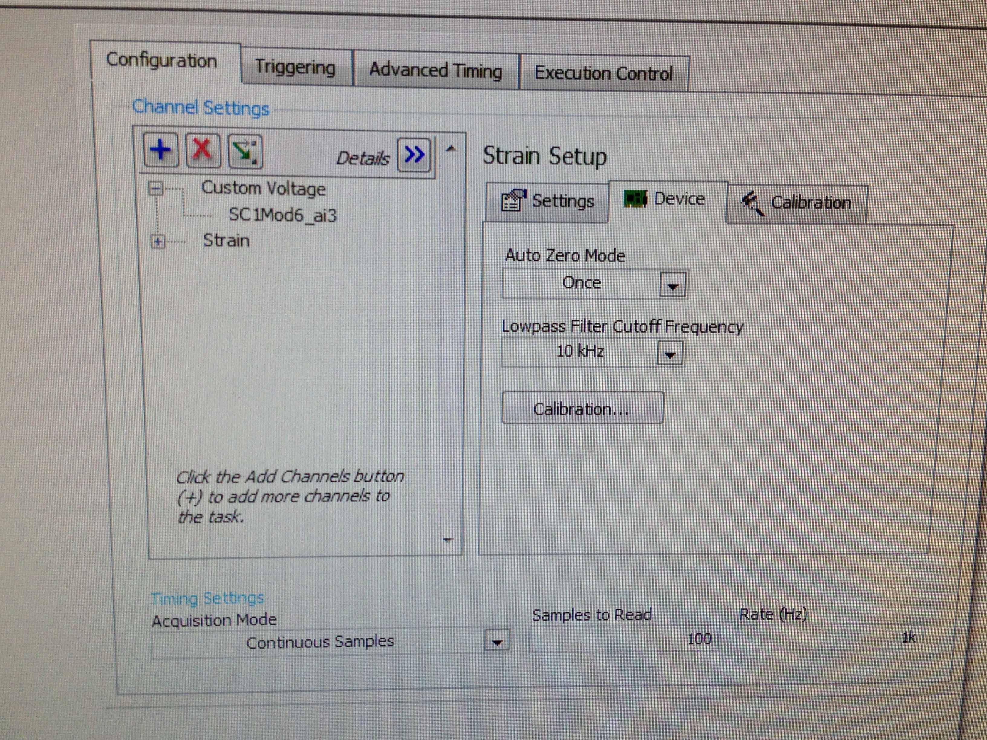
I use NI DA system to record the strain of a strain gauge 1/4 350 odm. The connection string would be extensometer---> SCXI-1314 (Terminal)---> SCI 1520 (block 2). I connected the cable to the S - P + and PIN the SCI QTR 1314. The value of the strain appear in LABVIEW EXPRESS. Now, I need to calibrate the extensometer (OFFSET REMOVAL and CALIBRATION of SHUNT). I'm stuck... I have two specific questions:
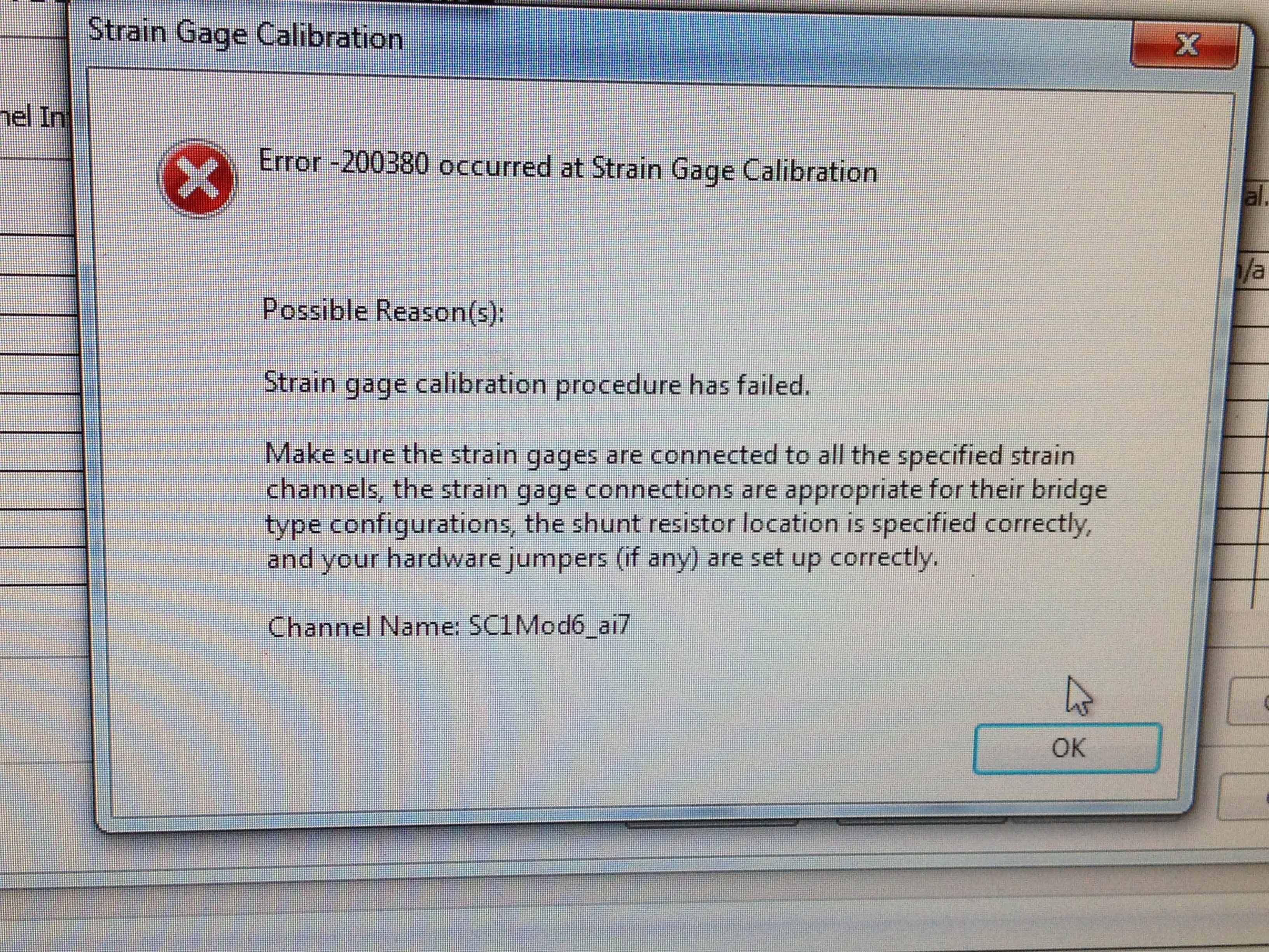
1. when I just check 'Offset the removal' in 'calibration' tab error-200380 orrcurs. Can you guys help out me?
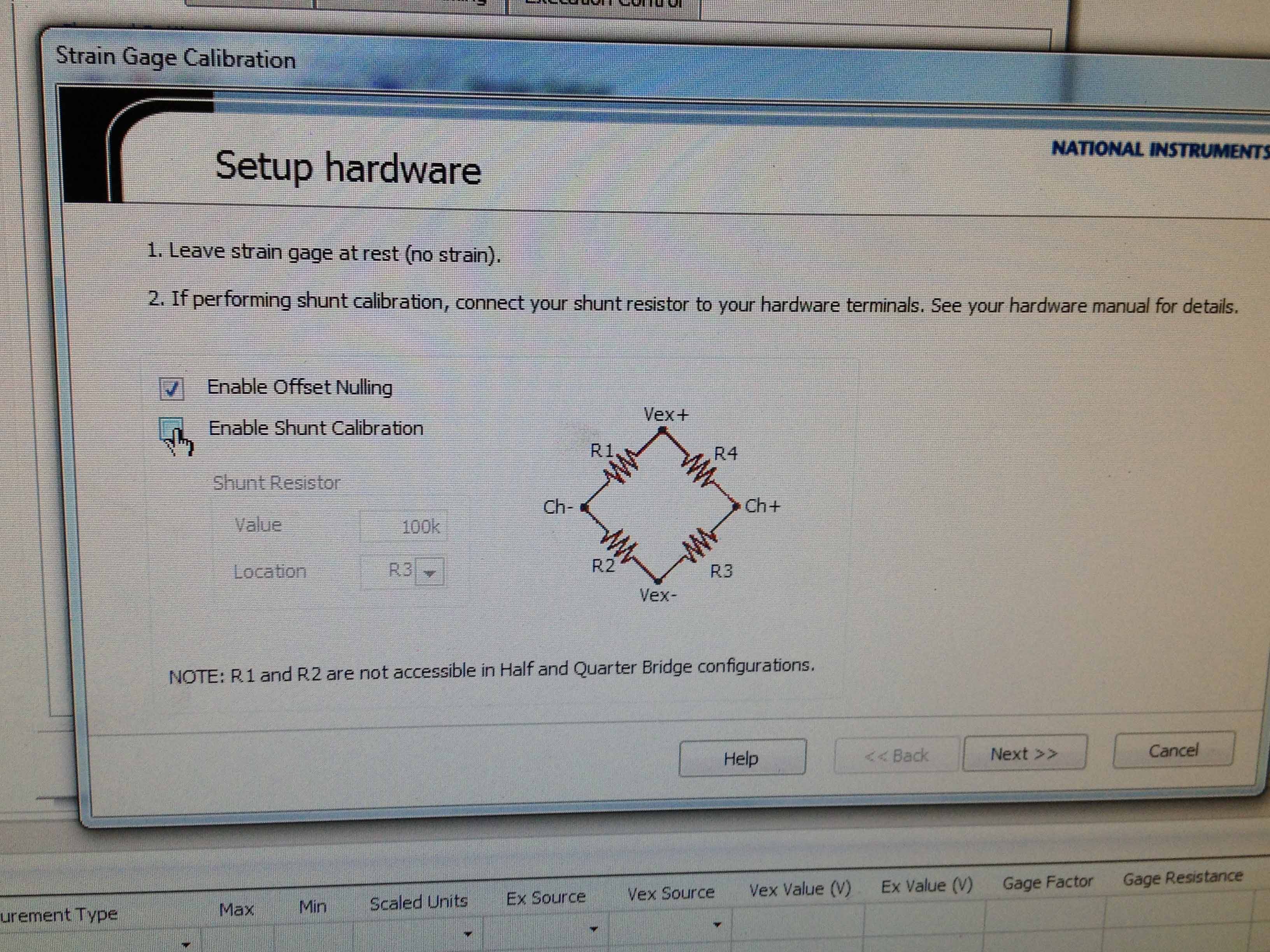
2. I noticed that there are specific pins for the SCXI-1314 shunt calibration. If I wanted to shunt calibration, must I change my wiring, so that the resistance of odm 100 k can be included in the circuit?
Thank you very much.
In your first post, you have the cable signal since the pledge is going to S- My first suggestion is to move your thread to signal S - s + if you don't have it already done. When 1/4 hanging bridge you only have access to R3 and R4 which are on the + next to the bridge. This high an error on your gain stage is usually a wiring problem or you maneuver the arm hurt in the bridge. In the calibration Assistant spend R4 R3 and see what happens.
How connected your pledge?
Of your pledge, you should have 3 wires. Vex + (red) on a tab of the pledge and shunt cal and GIS (tied together) on the other tab of the gauge. See my attachment to a vision of how I wired my system. Other colors, the screenshot of your wiring diagram looks like it should work. The difference being, ma sig + is green and the shunt is brown; where your of seems to be white and black. Anyway, double check your pledge and make sure that leads back to your terminal block are where they should be. In the 1314 default shunt resistors are all 100 kilohms unless something has changed in your system, you should be fine.
You can attach a copy of the file .seproj or tab 'Settings' from your screenshot strain gage configuration window. Things like factor value excitement and resistance will affect your calibration and output.
-
I can read two-channel USB-6008 using THE Signal Express?
Hello world!!
Is possible to read the two analog inputs at the same time?
Example: Using Signal Express, I need to read the (channel 0) analog input and analog input (channel 1) at the same time.
I try this but, the signal on purpose gives me an error message saying that I can't read several channels at the same time using the USB-6008.
Is this true?
Thank you
Ivo João
André,
Grato definition of pela.
SUA ajuda muito util faith.
SDS,
Ivo João
-
Download ip applications and the port using the expression language
Hi gurus, is possible to get the ip and port applications using the expression language / FacesContext?
example:
I have a request to the url:
http://120.120.120.120:7001/MyApp/faces/login.JSPX
I can get 'MyApp' (context root) using #{facesContext.externalContext.requestContextPath}
but I want to get the 120.120.120.120:7001 using EL.
If it is not possible using EL, I can't using javascript / java code in jspx?
What am I I make here is, I want to store multiple images in the folder on the server, and then I'll have my servlet read this image of the server folder and use this picture as the background image of the panelgrouplayout.
I want to save this image in a folder user can update this image easily that store this image in DB / application
Thanks before
Hello
Try #{facesContext.externalContext.request.remoteAddr}
If the above does not work, use a managed bean and expose the information as a property. Then use EL to reference the property.
private String remoteAddress;
public void setRemoteAddress (String s) {};
public String getRemoteAddress() {}
String addr = (facesContext.getExternalContext () .getRequest () .getRemoteAddr () (HttpServletRequest);
}
HttpServletRequest (Java EE SDK 5)
Frank
-
Alternating - Signal Express sampling frequency
Hi, Im trying to get data using Signal Express + NOR USB-6211, I put the sample rate to 44100 Hz. and everything seems to be ok, but when I checked the data I realized this time column does not increase in a period time constant (ie. sample FREQ not fixed).
For example:
1 / (Time (1) - Time (2)) = 43478,26 Hz.
1 / (Time (2) - Time (3)) = 45454,54 Hz.
and it constantly alternates between the two frequencies. I have to perform an FFT and Im not sure what is the actual frequency and which continues.
I appreciate any help on this issue.
Kind regards.
This seems to be a bug that NEITHER should be aware of if they are not already.
If you set the frequency of sampling to 44100, the actual sampling frequency will be (20 MHz / 453) or ~44.150 kHz. The USB-6211 case has a basis of TIME 20 MHz (±50 ppm) and this clock is divided by an integer to derive the sample clock. The sampling frequency is always be forced to match to the top if you choose a rate that can only be achieved with a wide divider. Regardless of what the file shows, map DAQ itself samples at a uniform rate (unless you use an external clock, or something like that...).
As for the behavior in the column duration... I know exactly how you look at it but I get the same behavior is written my data using 'absolute time' for the time column to an ASCII file (or by using a file LVM, which always uses the absolute time). With the help of 'on time' however gives me a correct result. I can't speculate on the cause... it seems likely to me that there is a comma floating rounding error (absolute time is in terms of seconds since 1904, so the software works with a large number at the same time requiring great precision).
Best regards
-
Can I have the user enter a variable that will be used to Signal Express?
We seek to use the Signal Express to collect data of analog sensors and load cells. We would like the user to be able to enter a variable that the program Express of Signal can act on. Is it possible within Signal Express?
Hello
When you select 'Change destination', it will fill with all stage settings that are supported for the given control used. Not all the steps or step settings are able to be adjusted when the operator mode. That is why you were only able to bind controls to step DAQmx Acquire and filter (they are only available to bind in your configuration steps settings). The forumla node is not able to reference an entry of order of the operator interface. You must manually configure the formula tab of configuration step for that particular step.
I would recommend if you want that more customized the user interface and approach programming using an application development environment. Signal Express is ideal for acquisition of signals and perform analysis and basic treatment, but if you want more functionality LabVIEW would be a better option.
-
Turning off IEPE signal Express with 9234?
I have a module 9234 and I can't understand how to disable IEPE while using the Signal Express. A new tab named "Device" appears when you watch 9234 modules, but which has only a drop-down list to select the AC/DC coupling. MAX displays a checkbox for IEPE, but I can't find that in the Express of the Signal.
Any suggestions?
Thank you
Hi ChrisCW,
In order to set the IEPE, you must choose a task of nonvoltage such as acoustic pressure or acceleration. You can see in the photo I have both source IEPE and value available. If a task of tension is the only one that has meaning for your application, you can always use one of the other and adjust the data.
I'll go ahead and submit a product idea to have this added to the task of blood also.

-
LEGO Mindstorms 2.0 crashes at startup when LabView Signal Express is installed first
When NI Circuit Design Suite education edition is first installed in a computer and the LEGO Mindstorms software second, the LEGO Mindstorms software does not work, he reported the following:
Error: A required file is broken
Possible solutions: reinstall the driver of LEGO Mindstorms NXT (tried but does not work)
Error code: 1003
Ordinal not found
The 18 ordinal not found in the library of dynamic links NIVISV32.dll
Error loading "fantom.dll".
The operating system cannot run %1
On other computers the LEGO software starts, it displays the part of the initial screen and then a small window will open saying that the Mindstorms software has made an error and that it will close. The previous report does not display.
If LabView Signal Express is uninstalled and reinstalled the software, LEGO, the LEGO software works.
I downloaded and installed the new and old of the NIVISV32.dll versions and is not correct the problem. I went as far as version 4.20 of the dll because it is dated in 2007 and dll files installed by the LEGO software when it works is also dated 2007, but if I install the dll without uninstalling LabView Signal Express, the continuous LEGO software does not.
Please advice how to fix this without having to uninstall first LabView Signal Express. If the LEGO software is installed first, LabView Signal Express will use and no not to replace the old version of the dll 2007 installed by the LEGO software? Y at - it an update of the LEGO software that corrects this problem?
I repeat: I know a solution is to uninstall LabView Signal Express, install LEGO Mindstorms and then reinstall LabView Signal Express but I have 60 computers already cloned and deployed with this problem, so I don't want to go to this long process to solve the problem. Computers use Windows 7 and the problems occur on both 32 and 64-bit versions of Windows 7.
Any ideas?
-
We have Labview 2012 Signal Express (version 6.0.0) installed on an XP computer and we want to upgrade to a Windows 7 machine. Will be the last version of Labview 2012 to work on the Windows 7 machine? The 2012 Labview Signal Express is used to control a cDAQ-9172 with module 4 channels thermocouple.
It's the Commission of LabVIEW. Please, click on Options and ask that the moderator moving your question to the Board of Directors SignalExpress. LabVIEW itself runs on Windows 7, but they are two different products and not many people here use SE.
-
How do I capture the output of voltage full bridge with Signal Express NI9219
Hello. I'm trying to do and calibrate a load cell with the installation of full-bridge strain gage. I use a NI9219 module with a cDAQ chassis. Is it possible to capture the actual output voltage? Signal Express gives me a value of strain, but I really need to know the output voltage. Where to look. I need only two channels for full-bridge. I think that could connect the wires to the two remaining channels and read the output voltage of the strain gauges which would be connected as a tension of the 9219 entry, but I think that Signal Express could give me the voltage and output voltage directly. Any input would be appreciated. Thank you! P.S. I only use this equipment on occasion and am not the more familiar with it, so keep things simple for me. Thanks again.
Hi jgh@AET,
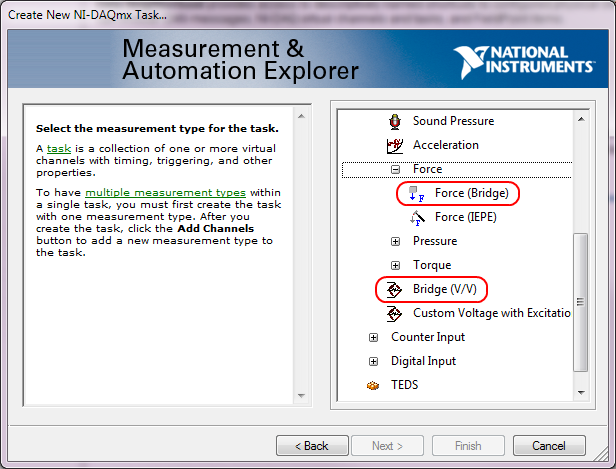
The NI 9219 measures the ratio of voltage full bridge in hardware sensors, allowing any variation of the voltage to cancel. You won't be able to measure the output voltage of the sensor regardless of the voltage without additional channels, but you can measure the ratio of raw tension using the type of Bridge (V/V) . You can also use the type of measure of Force (bridge) measurement of load cell with engineering units (N, lb, kgf, no strain).
This screenshot shows where the two Bridge (V/V) and Force (bridge) can be selected in the DAQ Assistant:
These types of measurement were added sometimes around DAQmx 9.1, so if you have an older version of NOR-DAQmx, your DAQ Assistant maybe not them. The latest version is currently 9.4 of NOR-DAQmx. Front of NOR-DAQmx 9.1, the approach to recommend to measure the load cells was to use the custom with Excitation voltage type and a custom scale. However, Tension Custom excitedly can't Bridge of calibration in the DAQ Assistant.
Brad
-
Signal Express version unknown problem with Labview VI
Hi all
I am trying to run 2010 Labview Signal Express VI. It gives me "unknown version" problem. When I checked for Labview versions, he said 10.0f2 and Signal Express can read the version of LabView 2010. I don't understand this. 10.0f2 is not just a patch for version 10.0? I will appreciate if someone can help me with this.
Kind regards
Kanu
Hi Kanu,
I tried to write a simple VI and its importation to the Express Signal and I have not had any problems. I use 32-bit LV2010f2 and Signal Express 2010. I have attached the VI I used so that you can try it yourself. I followed the instructions of this KB to create a distribution of the source file. If you follow this KB and still can't make it work, can you please post the VI?
Thank you
-
NI 6552 Signal Express sampling rate
I'm generating multiple signals for Signal Express. When I run them, some work well and others not, in other words, for some changes in sampling rate signals! Thera are two options in Signal Express: 1. read file waveform 2 sampling rate. to manually set the sampling frequency. In both cases, the rate is changed when I run the waveform of my 90 MHz to 100 MHz.
Any ideas?
Hello
The internal clock on the 6552 is generated from 200 MHz time base; Is that you can generate the frequency of 200 MHz/N where N is from 2 to a large number which takes up to 47 Hz. The driver for the Board of Directors will force the neerest value, so if you swipe from 90 Mhz to 100 MHz frequency, you will get 100 MHz in all cases. There is more information about the synchronization on the specs here:
http://digital.NI.com/manuals.nsf/WebSearch/E4C93B141B71ED93862573CC005E8EA1
Once, you run your project, Signal Express should show you the corced value, you can use this to read the actual frequency generated.
I hope this helps.
Juan Carlos
-
Display of recorder in Signal Express
I want to display a chart of tape display a signal from slow speed (f = 0.25 to 1.0 hz) signal that represents the position that results in a resistive (1 k) position linear tranducer (IE Unimeasure LX - PA series). This view must move left as new signals are acquired, rather than updating a display both as a field of application; IE more recent signal is on the right side, and there are N seconds are displayed on the left edge.
I'm a THE Signal Express 'newbie '. I have the signal from the NI USB 6211 correctly and displaying as a scope, but may not know how to change the view of what I want.
Any ideas or suggestions?
You must pass your signal through a step amplitude and levels:
- Add step > analysis > temporal measures > Amplitudes and levels.
- Go to Set Up settings and deselect RMS, leaving only the DC value controlled.
- From there just drag and drop this signal (the newly created DC signal) in the graph
- Right-click on the graph, and then select the Update Mode
- You should now have the opportunity to see in band, scope, or sweeping graphic.
Hope that's what you're looking for!
-
How to analyze the data of the cDAQ and Signal Express, especially after analysis?
In the first series of tests of my instrument, it took longer than expected for the race. Thus, the data was saved in 6 days. The file is too large for export to Excel. At the beginning of the project, I was as ignorant as I could go ahead and add analysis and the scaling of measures. By the scaling, I mean my data of switching current dew points or whatever it is that I record.
How to evolve the data to read the output data as expected 4mA = point of dew of-20 C or 0 PSIG? Can I pre program this to be recognized for each event?
For real analysis I am doing – I would first analyze the data I recorded and choose different points to send to Excel to graph and analyze. Is this possible?
Secondly, I would like to know how to scale and analyze my data in the project without having to do this later analysis in the future?
I have a cDAQ-9172 with LabVIEW signal Express 3.0 that uses four modules - 9211 2 modules of thermocouple, my 4-20 1-9201 module +/-10V module and 1-9203.
Thank you for any assistance.
Hi Patricia,
"' You can do this by adding a step Load/Save signals ' analog '
. I hope this helps! -
Use Outlook Express, the links on newsheets etc. are no longer works
When I click on a link, it is no longer connects. Everything else seems to work OK (fingers crossed!)
Piece of cake.
Hyperlinks do not work in Outlook Express or in Word (revised 29-Apr-09)
http://support.Microsoft.com/kb/823301Hyperlinks do not work in Outlook Express after you put upgraded to IE7 [or IE8] (revised 29-Apr-09)
http://support.Microsoft.com/kb/929867If still no joy:
With the permission of MVP Frank Saunders. [RIP]
If nothing happens when you click on a link:
Open Windows Explorer or on the control panel.
Go to tools | Folder options | Types of files.
Scroll to [NONE] URL: HyperText Transfer Protocol (NOT the shortcut URL: Internet) and select it.
Click Edit or advanced, depending on your version of Windows.
Choose 'open '.
Click on change."Application used to perform action" should read:
"C:\PROGRAM may EXPLORER\iexplore.exe" - nohome (check the path to)
Iexplore.exe to ensure that it is correct and use the double quotes).DDE should be checked and in the boxes below, you should have:
#1:
« %1 »,,-1,0,,,
#2
IExplore
#3 (white)#4
WWW_OpenURLProtocol URL: HyperText Transfer with Privacy should be the same.
If the foregoing is correct, uncheck the box: use DDE.
Maybe you are looking for
-
Tried to open facebook. Firefox constantly opening new tabs for facebook to infinity
Never had problem before above. We also have a laptop that is not experienceing this problem-(in a different name facebook account)
-
purchase can not be completed contact support itune?
why I can not buy any games it keep saying your purchase cannot be filled itune contact support? How to make that straight and I bought a gift card on apple store and put 15 dollars in it still cant buy everything?
-
Satellite A300-1MX - sound & video are not in sync and video lag
Hey everybody, I bought a new Toshiba Satellite A300-1MX two days ago and had installed XP on it with Service Pack 3. I only noticed now that I tried to play a video that I took with my camera it was very laggy, the audio and video are out of sync an
-
When I open a link "in a new window' in IE - 8, the window is small, how can I do open in full page?
When I open a link "in a new window' in IE - 8, the window is small, how can I do open in full page?
-
How can I change my SSID on a WRT400N?
Each help topic I can find says you can edit these on the page "Wireless > Basic Wireless Settings ' of the web console. However, when I do these values are not editable. He pointed out the SSID and passphrase for each of the two groups, but I can'