Arduino MyRIO UART question
Hello
I do the Arduino MyRIO UART communications
The issuer is the arduino which continue to send 0 x 68 and the MyRIO is the receiver
The data frame and the baude rate are the same on both sides.
The receiver can read the length of the message list 1 (the number sent only, so the length is 1)
The problem is the character is not displayed (this is always 0)
I have attached the arduino code and myRIO vi.
Is there someone who gives a solution for this?
SergioMa wrote:
Hello
I do the Arduino MyRIO UART communications
The issuer is the arduino which continue to send 0 x 68 and the MyRIO is the receiver
The data frame and the baude rate are the same on both sides.
The receiver can read the length of the message list 1 (the number sent only, so the length is 1)
The problem is the character is not displayed (this is always 0)
I have attached the arduino code and myRIO vi.
Is there someone who gives a solution for this?
3 information on the same subject?
We can see them. They are all still there for people to see.
There is no need to continue to ask the same thing again and again and again.
And you even wrote that you got it working.
Tags: NI Hardware
Similar Questions
-
Arduino MyRIO via UART communication
Hello
I am trying to achieve the data between MyRIO1900 and Arduino via UART communication.
Interface UART on Arduino Uno is minus 16 MHz clock.
The UART to myRIO can set baud rate. However if the frequency is different from the Arduino, the connection will not be built.
How to set the frequency of MyRIO UART? What is the default frequency of MyRIO UART? Where can I find this setting?
I don't understand. If the transfer speeds are the same, you should be fine. The clock frequency is used to calculate the bit rate and is the rate that data is transmitted/received.
-
Hey guys,.
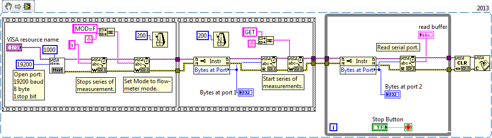
I have a the Sensirion AFS1430 sensor RS232 interface. Now, I'm trying to contact him with the following code:
The problem is that I get no response at all. Bytes to port is always = 0. A warning I get in the while loop:
VISA: (Hex 0x3FFF0006) the number of bytes transferred is equal to the number of entries requested. More data may be available.
I also tried to change "line break" to "carriage return" always the same result.
With the help of an oscilloscope, I see that what I write is sent via TX, but nothing happens on the port for the while loop (TX is high all the time).
I'm getting a little frustrated...
Kind regards
Slev1n
More importantly - you have a line driver/transmitter/receiver connected to your myRIO? The UART pins on the myRIO are not RS-232 levels - they are 3, 3V (5V tolerant). If your meter's RS - 232 - there signal levels could be anything up to +/-15V - you might damage the pins of your myRIO - you need to put a line transceiver to convert RS-232 up to 3.3V-level signals.
-
Looking myRIO Xilinx architecting-7010 SoC I am bit inntrested in the workflow for the GS. How does the bennifit myRIO use a system on chip instead of a regulare CPU and FPGA not in the same chip.
4 way could there be to manage a VI?
With FPGA and RT (CPU)
Only of FPGA
Only RT
only the windows
I am comfused, is it any good article/doc describing this?
I found the image in a PowerPoint on the www. -What the task split like this betwheen the CPU and FPGA?
Hello
Please see this link. This can help you understand the architecture of RIO, and there are many whitepapers available in ni.com
-
myRIO video recording Question
Howdy all!
I am currently using a camera to create a video on a flash drive. The camera and USB are connected to a myRIO, so both work with the myRIO. I have to the were completely failed in creating anything again.
I created my VI using the example of capture and record to AVI and only changed the save location. Whenever I run the code, an error occurs after the IMAQ AVI2 Create function: error-1074396070. It simply indicates that "IMAQ Vision: unsupported function.»
My suspicion is that the myRIO does not support functions for video creation, because the program works fine on my laptop when I run without the myRIO. I've updated the drivers on the myRIO, but the problem persists.
If myRIO does not support the Vision, is there another way I can save video using the myRIO?
Any help would be greatly appreciated!
Thank you!
-Aggieimperator
Well, I checked on a 1900 and I could not also get AVI functions to work. I suspect that they are not supported by the myRIO. Would you rather save the pictures on the flash drive and then convert them to an AVI file?
-Tanner
-
question of myRIO sequential clip
Hello
I realized a CLIP, and I wonder how to implement it.
The vhdl code is used to send data on the falling clock edge and read in the data on the falling clock edge.
Send and receive takes about 30 clockcycles. The code is based on a state machine and starts to send once an enable signal is given. Transmit/receive all the bits, he returned to idle.
I read that the CLIP would go even if it is not placed in a loop. However, when I do a test vi that has an LED connected to a few outings, it seems that it is only launched once? Or is it actually running, but the LED is not updated? I don't know how to implement is.
Use this CLIP in a time loop of single cycle? He would still use the fronts and the clock edge? And it would cause problems because it is sequential and combinational not?
Thank you for your help.
kind regards,
Bastiaan
Hi Bastiaan,
You read a 40 MHz signal each 25ns. So that means that you will read the same value of the signal in each iteration you will always show the same value and you will have a consistent performance. In order to get a signal to the correct frequency on you must perform the loop with a frequency of at least double the signal. You can create a clock FPGA derived in the way that this article describes. Use a clock of 80 MHz for the SCTL.
http://zone.NI.com/reference/en-XX/help/371599H-01/lvfpgahelp/creating_fpga_derived_clk/
Let me know if it helps.
Kind regards
Tom
-
Hi all
Small question.
I just played with the myRIO, so forgive me if this question is stupid, but it is possible to connect a USB bluetooth dongle? Otherwise, what is the best way to connect a bluetooth to the myRIO interface?
Thank you!
Hey tonverra,
In order to use a USB Bluetooth dongle with myRIO, you will need to make some changes to the operating system. The Group NEITHER Linxu Real is the best resource for OS customization issues.
Ferdinand, you could use a USB Bluetooth dongle simple with an interface UART or SPI as the BlueSMiRF without any OS custimizations. Usually, these modules offer fewer features but can be quite good depending on what you are trying to do.
-Sam K
Join us / follow theGroup of pirates of LabVIEW on google +
-
Engine for MyRio adapter command 2 DC motors
Hello
I have a question about the adapter engine for the MyRio. I found the following code example:
https://decibel.NI.com/content/docs/doc-45592
This afternoon, I was able to drive a motor continuous using this VI, but I want to use to control 2 Motors continuous. I tried the following (see photo) and it did not work.
What should I do for the second DC motor?
Thank you!
Hello
Well, the next time you post, it would be useful to have all the information to start with (what does your system, errors, measures
you have taken to solve the problem, etc.). This way more people will respond and we can help you more easily.
By parallel loops, I just run two processes in separate loops at the same time in the same VI (what they do on the link).
If you think about it logically if this initial process is running one engine, then do the same exact process but that it points to the
second motor will run the second engine. So, if you include the two pieces of code (exactly the same but different engines references) in the same VI then it can run two engines.
If you look at the link I have attached before she speaks of two ongoing processes at the same time within the same VI.
You can then use queues and the authors of the notifications (look in them) to communicate between the two processes you use, allows from Control Panel even before to control them and stop them both at the same time.
With this, you should be able to all both enforce.
Hope this helps
-
How to set an application built using the C API for myRIO 3.0 to run when starting on a myRIO-1900
It is even possible to define such an application to run at startup? If so how would you do it?
I've compiled a program using the API and eclipse distribution OR and can run Eclipse or by running while SSH in the myRIO. Is the only document I could find about this one: http://digital.ni.com/public.nsf/websearch/B37FA04A1CB84B6C862571A30060EF03?opendocument&Submitted&&...
The link is a little outdated, so I'm not sure of the relevance, it is today. I changed the lines of lvrt.conf to:
RTTarget.ApplicationPath=/c/ni-rt/startup/startup.rtexe
RTTarget.LaunchAppAtBoot = TrueNone of the settings seem to do anything. I also tried to run the program as a script using rc.local which does not seem to be used in the same way as it is in Ubuntu. My compiled pogram does not include the .rtexe extension although I can add it later that might not be the same.
I made sure that startup programs 'disable' has been disabled on the Server Web myRIO.
Thank you
Just in case someone has a similar question:
-
Hello friends,
I have a question. I need to trigger an output of Myrio with a single pulse. After the pulse, the output will remain active. Then with another single pulse, the output will be switched off. Should what tool I use?
Thanks for listening,
Kind regards
David
Hi Davi08,
I did a little research for you answer and I found another "NI Discussion forums" forum that maybe can help you.
Try using this link, I think this will help you.http://forums.NI.com/T5/academic-hardware-products-Elvis/myRIO-digital-trigger/TD-p/3278560
Best regards
-
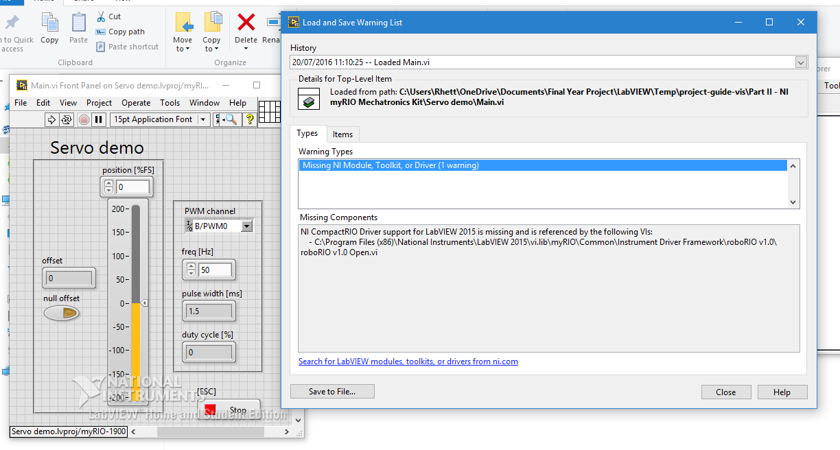
myRIO Servo demo does not: Servo sweeps back
Hi all
For the first time using LabVIEW and myRIO and I thought I'd run the demo of Servo. The question that it displays the following error message:
If I choose to ignore the error my servo works but don't stop at a point (hold the angle) and sweeps rather backward. This can be seen in the following video:
I'm honestly at a loss, I have virtually no experience with this hardware and software and the standard demo software does not work. I use an analog servo CS - 239 MG Corona.
Any help will be greatly appreciated

Hi Kathryn,
Thanks for all the help, you were extremely helpful
the solution was that I needed to power a battery pack as the myRIO provided far too little power. I found the solution in another forum of NOR and the OP knew exactly the same question. I have a battery pack on order and will update with the results.Kind regards
Rhett
-
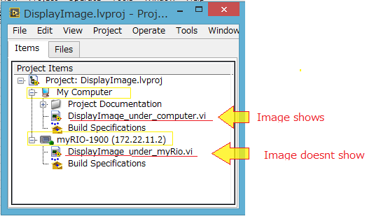
Display image on vi as myRio problem
Hello

This system supposed to be an easy task, but I don't know why it does not work. I am trying to create a game by myRio 1900 and I'm putting a jpeg image. However, I get an error message or an empty image on the Panel before the myRio Vi (Vi project myRio label) [see photograph below]. On the other hand, if I create the same VI under my computer, the image shows without any problem. What should I do to enlarge a picture on my VI as myRio. I need the image either on this VI because I am creating a program requiring myRio and it may not work properly if it is not under label myRio (I need its integrated sensor). I am attaching a zip file of only the part display image of the commandments and not my whole project easier to visualize.
Problem in brief:
Please see the project (as a zip). The vi computer label works and the vi under myRio does not.I want to solve:
I want to put an image on VI myRio label.I have:
MyRio Labview 2014
MyRio 1900
Already tried to: (but unfortunately did not work)
(1) put the jpeg file in the USB key and plug myRio directly. I gave the file path ' / u/bg.jpg ". (File system)
2) created by Subvi from 'computer' then it reminds on the (main) vi under myRio. And vice versa (Subvi myRio and MainVI on 'computer')
Please ask me any questions if you need further information. I will answer as soon as possible.
Thanks in advance for your help,

I am very greateful for your time.
Stephany
Stephany,
It seems that reading JPEG/PNG/BMP screws are not based on targets in real time, as your myRIO. As an alternative, you can get our Vision of shared resources (I think you need to install with Vision Development Module), install Vision RT to the myRIO and use the IMAQ ReadFile VI to open the file on the myRIO.
-
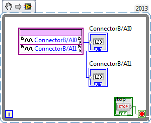
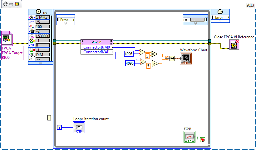
I'm new to myRIO and use it to measure sine wave (0V to 5V) of up to 10 Hz 20 KHz. I also quickly transformed of Fourier (FFT) of the signal measured in real time.
Sideways FPGA of things, I try to keep things pretty simple, just read 2 channels of AI (connector B: AI0 and AI1), therefore potentially able to read each HAVE 250 kech. / s (as the unit has a capacity of 500kS/s). Does that mean this program gets a two analog inputs data exactly every 4 microsecond? If this is not the case, how can I make sure that the data is acquired through a fixed sampling rate?
I realized that we can add to the FFT in FPGA function, but I wanted to manipulte the acquired data of analog inputs before it is sent to the FFT, which I don't know how to do now. Can someone explain me how do the arithmetic data (muliplication, division and so) on the acquired data and analog inputs to reducde the 12-bit resolution 10-bit to program FPGAS.
Later, I created a myRIO program to read analog data 2 FPGA program which continues to turn in timed loop. In the program myRIO, the timed loop is configured to 1 MHz clock source type by a delay of 25 microseconds.
This configuration means that the loop runs exactly every 25 microsecond?
When I set up the less than 10 micro second time, myRIO has stopped working. Why is it so?
Is it because myRIO cannot run as fast as FPGA?
It is advisable to make the FFT of myRIO side analog data or FPGA?
When I tried to do FFT using the power spectrum of myRIO side, he asked for waveform data. What I acquire is data analog. How can I convert in waveform data?
If I read in the forum for help, I couldn't have the full answer to my doubts
Discussions at the Forum I did reference:
A lot of good questions here, I will try to answer as much as I can so as to offer a bit of advice.
First of all, if you are looking to acquire data at a very specific rate on the FPGA, you'll want to use the Timer VI. You are also going to use a FIFO of DMA to transfer data of FPGA in real time. A node read-write using as you do now means you'll run out of samples, or read the sample even several times. The link below is a very good tutorial on how to do what I described above.
http://www.NI.com/Tutorial/4534/en/
Later, I created a myRIO program to read analog data 2 FPGA program which continues to turn in timed loop. In the program myRIO, the timed loop is configured to 1 MHz clock source type by a delay of 25 microseconds.
This configuration means that the loop runs exactly every 25 microsecond?
When I set up the less than 10 micro second time, myRIO has stopped working. Why is it so?
Is it because myRIO cannot run as fast as FPGA?
In general, you should not run a timed loop much faster than 1 kHz. Using timed inside loop knots, you can monitor the real rate of loop during execution to see if f you meet your needs of the moment.
The portion of your myRIO RT is slower than an FPGA in the sense where it cannot manage the rates of lines 40 MHz (he makes up for it by being able to work with much better pictures) and it is important to remember that it is just a computer. The advantage of a real-time operating system, is that you have more control on the Scheduler, not that he is faster (less jitter, not faster code). There is more good reading below.
http://www.NI.com/white-paper/3938/en/
It is advisable to make the FFT of myRIO side analog data or FPGA?
When I tried to do FFT using the power spectrum of myRIO side, he asked for waveform data. What I acquire is data analog. How can I convert in waveform data?
I would say that it is generally advisable to treat your FFT on the side FPGA as long as you have the resources available, but for many applications probably little matter ultimately.
-
myRIO ADC problem: side affacted channel of its previous channel
Hello
I use several channels ADC myRIO now and facing a question about it.
I use 3-channel ADC Port A: AI0 AI1 and AI2.
I have connected AI0 in the middle of a potentiometer for voltage accoss it. And connect anything to AI1 and AI2.
CDA works very well. I can move the potentiometer valtage perfectly AI0.
However, when I changed the value of the potentiometer, the CDA of AI1 and AI2 results changed also, 0, 1V to 0.8V about. Please note I have nothing plugged in these two ports.
Is this true? the ADC AI1 and AI2 and AI3 same (PORT A) port are affacted by AI0?
When I connected AI1 to an Anolog output senser, the result was also affacted by the potentiometer which was connected to the AI0.
When I connect AI1 in power, he was out of influence.
Did someone already had such a problem? Can someone help me to solve it?
Thank you
Fisher lah
It is the response of support OR:
Please note the small change you notice when both of your strings are attached can be due to several factors such as the wrong wire shielding, etc and EMC (electromagnetic coupling).
What is a floating channel terminal, random or variation is normal and due to internal correlated myRIO circuits and should not be a cause for concern.
Well, I'm still very confused.
-
High speed FPGA for MyRIO personality
Hello
I started on My Rio 1900 who I am trying to program in C language, so without the use of Labview.
I did sample a signal.But I would like it sample at a higher frequency that it is possible with the default standard FPGA personality.
I downloaded it on ni.com, but installation requires Labview 2014...So my questions are:
How can I do to work with the personality of FPGA high-speed in c and how do I install it without Labview?Thanks in advance for your help
Best regardsFrançoise
Hello fm16,.
Personality OR broadband to MyRIO without LabVIEW FPGA is not supported, sorry. As you can see:
1) http://zone.ni.com/reference/en-XX/help/373925C-01/myrioreference/myrioref_high_throughput_vis/
2) http://www.ni.com/tutorial/52864/en/
use high-speed FPGA personality VIs to LabVIEW, because the Add-on's code in LabVIEW, so that you cannot use in C.
Best regards
Mariana
Maybe you are looking for
-
Reinstalling Windows XP edition family MCE on Equium A100-147
After a blue screen on this laptop, I ran chkdsk /r and when he pointed out several times there mistakes I replaced the ghost drive it. I did a repair reinstall and a large number of files could not be "copied". I reformatted the drive and ran verifi
-
new faucet botton has stopped working after a few updates
Hi, FireFox has had a few updates for IDM modules as usual, but after he (new tap botton) stopped working, even the new tap since the right-click option does not work, please help
-
My iphoto garbage will delete (empty). Over 4000 photos are in the garbage awaiting removal. Help!
My I have garbage removal site Photo will NOT delete. I have over 4000 photos etc stuck in limbo. Help!
-
Try to set up my mini iPad and it won't let me choose a network that no backup is compatible with the version of iOS on iPad (9.1)
-
MyDAQ handeling voltage 10 v If we have the tension goes down
Hello! I use a MyDAQ and I need to get a signal from a different device. Here's my question. Looks like the MyDAQ can manage 10 +-volts, but can it be damaged if I give him a 24V signal and use a lot of resistance to lower blood? I show a short way o