Attributes of digital waveforms, LabVIEW 8.5 freezes
I have 6 cards LVDS, 16 analog inputs by card. I want the user to select a subset of the 96 channels available for display. The attached code causes my pc to freeze. Not always, but sometimes when I switch between the selection of channels. Select either Chevron1(24-channels), Chevron2(24-channels), Chevron3(24-channels) High-Power(3-channels) or enter your own strings as string from 1 to 96.
This problem can be connected with the bug of attributes known to digital waveforms. If all goes well, my code is self-explanatory.
See post http://forums.ni.com/ni/board/message?board.id=170&thread.id=349313
For more details of the refrigerator used in the attached code.
Hi bmann2000,
I don't think that we will be able to get the 8.6 control works as you want because of the CAR. However, I have a suggestion that I have attached to this message. I used an array of strings to create indicators based on your logic of origin. It is not as clean or well tidy as your desired result, but I think it might be a solution. This is a screenshot attached. The VI is saved to 8.5. Despite the name of the file to the contrary.
Let me know what you think,
Tags: NI Software
Similar Questions
-
export forms of digital waves + labview
Hi all... I am a newbie with labview and I want help for the beginning... Well, I'm working on a project and to start, I have to use an arbitrary signal and an oscilloscope so that I can see the graph of it (for simplicity I used a sinus at the beginning...) and then I use an A/D converter and the digital output must be saved in a .txt file, so I can read... So I wired the sinuses with the A/D converter, but then I can't make out of it compatible so that I can save it... I used the component 'export waveforms to the worksheet file.vi', but it says error different type of data we can't plug a 'digital waveform"at the entrance to the file"table 1 d of waveform (DBL)? I used, and some other components for recording to a file, but it will be better... What hurts? Please if someone can help me... I would be appreciated!
-
Continuous output of digital waveforms on PCI-6602
I use 6602 PCI to get a continuous 1 MHz square wave output of DIO1 ~ 32 sequentially controlled by LabVIEW. I Ctr0 to generate a clock 2 MHz and used Ctr0InternalOutput as a source of sample for DIO1 clock ~ 32. I have attached the code and the texture as follows.
The code works fine on PCIe-6251 and digital waveforms of 1 MHz is very stable.
But when I run on PCI-6602 I got an error-200077 (you asked for: sample clock; you can request: on-demand).
6602 PCI does support material timing? I found no information about this its specifications. If she can't, how can I avoid this problem and get what I want? Thank you!
Yi
Version: LabVIEW 8.2
hardware: PCI-6602
Hello
Have you looked at the specification for the 6602?
http://sine.NI.com/NIPs/CDs/view/p/lang/en/NID/1123
Click on "specifications". Scroll down to "digital i/o". Watch "Timing". It clearly says "software".
The DIO lines on this Board are not timed by the hardware. They are clocked by the software. The data sheet that explains very clearly. That's why you see the error clock sample - that the Council can't stand DIO clocked by the hardware.
The 6251 supports clocked by DIO material, so why your code works very well with this Council. You can do the generation of signals with a 6602.
Hope says.
d
-
Digital waveform graph refuses to change the names of Bus
I try to display digital signals on the graph whose lines are grouped. It looks like the functionality exist to group the lines of 'Bus '. There seems to be a way to rename each Bus of its default value 'Bus 0, Bus 1, etc.' as an Express VI called 'group digital signals' that does it. Looks like the express VI edition of the attributes on the waveforms in order to rename the bus. Attributes are NI_ChannelName for the Bus and NI_LineNames for the lines that make up the bus.
When I code, line names are renamed according to what I want, but the Bus names remain by default 0, Bus 1 Bus, etc.. Is there something I need to do to rename the bus?
(see annex VI)
Thank you
Dan
So, he works with the good old property node. Simply set the Active Bus and then write Bus.Name.
I've been led to believe that attributes work based on the example here.
-Dan
-
Reference library of digital waveforms of SPI for LV 7.1
Hello
I'm using LabVIEW 7.1. I want to implement SPI communications on a NI HSDIO (PCI-6541) device.
The SPI Digital Waveform Reference Library (http://zone.ni.com/devzone/cda/epd/p/id/6163) is available for LabVIEW 7.1? Someone at - it successfully he converted from 8.2 to 7.1?
The screws are also available under the reference Application Communication Protocol series for digital devices of waveform page (http://zone.ni.com/devzone/cda/epd/p/id/6200) available for LabVIEW 7.1?Any help would be appreciated. Thank you.
Hello
Unfortunately there is no simple way to convert libraries back to the 7.1.
My suggestion would be to download an evaluation copy of LabVIEW 8.6
You could use the trial period to open libraries and use as reference to re-create what you need to in 7.1.
Hope this helps,
John
-
How can I write a digital waveform to the digital output (traditional DAQ)
Hello
I use a NI 6023e, PCI, with 8 digital outputs. I generated a digital waveform. How can I write for a specific digital production line now?
I only have Labview 7, so I can't use DAQmx.
Thank you very much
-
Generate digital waveforms of high frequency
Hi all
I have some problems. Today, I am generating several digital high frequency waves with my DAQ (PCI-6251) card. The duty cycle of the waveform must be adjustable.
The required frequency is 100 kHz.
To do this, I have tried several solutions:
(1) I used counters in the acquisition of data to generate waveforms, and it worked fine. However, I have only two counters. In my application, I need to at least three waveforms with different cyclical report;
(2) I used a 'loop' and structures 'case' in labview to build the model of waveform and then feed them to the digital I/o. However, the problem with this solution is that the frequency of the wave generated cannot be high.
(3) I used a 'digital' generator in Labview to generate waveforms and then feed them to the digital I/o. In this case, the time base is from an external source (200 kHz). However, with this solution, the cycle is not adjustable.
Please give me some advice on how to make these waveforms. Your assistance is appreciated.
OK, so I may be wrong, but after mucking around for a bit, I realized that the regeneration should be automatic - in other words, if you a pattern to the right and then just leave your VI work in a while loop, you will find that the generation is continuous. Discover the correlation dig write metered in the finder for example Labview. You can leverage this as you get the cyclical report you are looking for. You can split the signal down what you write a single period consisting of a series of 0 and 1. In other words, if you want a wave of 100 kHz with a cycle of 20%, you write a pattern of digital waveforms a 1100000000 at the rate of 1 MHz. Using this technique, the resolution of the cycle will be limited by the on-board clock speed (80 MHz = 0.125%).
Let me know if this makes sense - I am unable to reproduce this on my desktop and have never had to do this before.
Cheers, Matt
-
How I ouptut a digital waveform, it has collated and compare it to the original with a usb-6211 box?
I want a digital waveform to a circuit of output, read the return signal and compare the original to the read signal. I use a usb-6211 housing is it possible and if so, how?
Use a comparator "equals sign", mark the post as a solution if you have the makings of what you wanted.
-
Generate a digital waveform like memory on PXI cards
Hello
I'm looking for a way to send a large digital waveforms using a PXI digital signal generator. I saw DIO HS cards, but their memory is smaller than the files that I want to transfer. My understanding is that the PXI backplane bandwidth 132 MB/s. So, I shouldn't be able to stream a digital signal from the memory of the card that is slower than the CPU? For example, 50 Mbits / second (equivalent to only 6.25 MB/s)? However, I think I understand after reading their textbooks is that you cannot continuously transmitting a large waveform of the processor memory file, you must transfer the file to the memory of Council first and then transfer that out.
Does anyone know if there is a way to have a flow of digital signal generation card an arbitrarily large directly from memory to the processor of digital signals? Or, what is the fastest card of pxi digital signal generation that does not require the storage of Council first files?
Thank you
Isaac
Hello Isaac,.
Take a look at the following area developer.
NOR-HSDIO Stream from disk (generation) using Win32 file IO
Note that you will not be able to take full advantage of the maximum rate of update HSDIO devices, because the data must be transferred in a bus. Some other considerations are the width of the data as well as the HSDIO device you select, which may depend on other requirements not related to the size of file or waveform (for example the standard voltage or whether you need hardware compare). For more information, take a look at the developer following items area.
Data streaming of Architectures in the PXI systems
The use of National Instruments Logic Analyzer and generator of test patterns SolutionAdvanced features of e/s high-speed digital devices White Paper Series
-
Can someone tell me how to extract a part of a digital waveform?
I am trying to extract a part of 2 analog waves (using the http://zone.ni.com/devzone/cda/epd/p/id/4149 for example) analog signals is synchronized with a digital waveform. I need to extract the same portion of a digital waveform. Can someone tell me how to add the digital extractor in the example above?
Hello
Here's your extractor example slightly modified in order to add the digital data extraction.
The principle is exactly the same, the tricky part is how to get digital data which is different from analog data.
You can also add nodes property to identify the value read on the analog graph sliders on the digital chart.
Kind regards
-
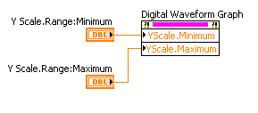
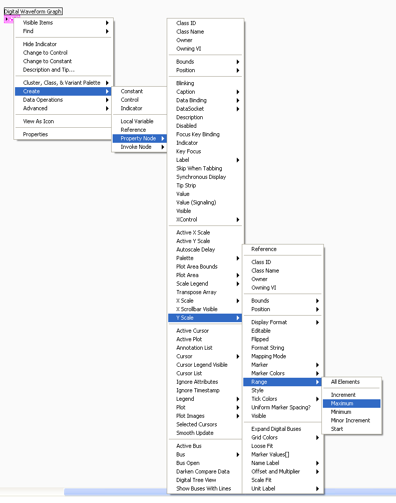
Is it possible to scroll on the y-axis of a graph of digital waveforms?
Hello!
I use LV 8.5.1 and I want to draw 64 signals on a graph of digital waveforms.
But if the graphic is too small, I see not all signals, and if I enable auscale on the Y axis, so the signals are not recognizable.
Is it possible to activate the scrollbars on the y-axis?
Thank you.
Hello!
Try to use the nodes property Y scale with a slider horizontal/digital control. As:
Find it here:
I hope this helps!
-
How to record a digital waveform with timestamps for each sample?
I am generating a digital stimulus and capture the digital answer using 6552 HSDIO. The captured response is data digital or forms of digital airwaves.
I want to save the captured digital answer and save it in a file in spreadsheet showing the timestamp for each sample. How can I go to a digital waveform to a worksheet that contains all samples and timestamps for each sample?
Comvert digital to analog is just the wrong function. And when you converted to U8, you just threw the calendar information. Try the code below. He puts the time in a single column. If you want to only two columns, its an easy mod.

-
Table 1 d of digital waveforms
I have a table 1 d of digital waveforms and I need to work with the data. I can't get the 'mass' to work with any function table or any other type of function also.
I need to be able to convert these so I can find a particular value in the table.
Thank you.
So you're just trying to get inside the matrix? Use a loop For or an Index Array node.
-
Count the number of 1 is present in digital waveforms obtained by converting the pulse signals.
Hello
I use Analogtodigital.Vi to convert the pulse of the sequences in digital.signals.I am able to get the representation of digital waveforms of impulses.
But how to count the number of 1 is present in the converted digital waveform. I want to count the number of 1 is present in the digital waveform converted.
Thanks in advance.
Have you tried the block scheme of similar to the Digital.vi of opening?
It creates an array 2D uncompressed 1 and 0, which is the binary 16 bits A/D conversion of each element in the array Y of the input waveform. You can use the DWDT digital Array.vi Boolean to convert a 2D Boolean table. Then convert Boolean values to 1.0 and summarize the array of integers. The sum must be the number of 1 bits in the digital waveforms.
Lynn
Note: The VI attached is saved in version 8.6. When I have it saved for the previous Version a warning was generated about the possible differences in the versions. Let me know if it doesn't work, and you are using which version of LV.
-
static/digital waveform output and low frequency measurement of voltage - SMU-6358
Hello
1. I have an attached VI [digital_voltage_output] who must generate a logical true or false static state in the output of the device/port0/line1 Word to say. When the VI works I click the button several times, but nothing happens to the port0/lines1.
2 such a thing [digital_voltage_waveform_output_square] if I'm trying to generate a digital waveform to pin the same with the waveform generating VI. If I connect a waveform chart to the output of the generator function VI, then the chart will show me the good waveform I want, but still nothing is written to the text file.
3. I have read the manual for the X series cards, but it remains unclear for me a little how to things of the road in LV I have a measure of the frequency measurement VI low frequency that I downloaded. It offers me the ports for the supply frequency - ctr0, 1, 2, etc. As far as I'm concerned the PFI ports are responsible for these types of actions. How can I find out the LV that I want to connect say ctr0 and pfi0? »
I use LV 8.6.
Thank you
Kriváň
Hi Kriváň,
The problem you had with the choice of a specific digital line as a physical channel, is that the control that was previously used in this example was created for a data acquisition task that uses a whole port rather than a specific line. I was able to overcome this problem by removing the control and recreate. The control now gives you the option to choose the specific digital lines e.g. port0/PXI1Slot2/$line0.
I was also able to overcome the error of-200802 you mentioned. I was able to do this in a real constant of wiring at the entrance to auto-start the VI DAQmx writing then remove the DAQmx beginning the subsequent code VI. The modified code is attached.
I hope this helps.
Best regards
Christian Hartshorne
NIUK
Maybe you are looking for
-
I can't see the pictures of the auction. Be precise in paths that I must take to fix, as the LOCATION of every step of the way. Thank you
-
How to determine when my separation of the two edge counter starts counting
I looked through a ton of Daqmx properties, the web and the forum OR to find answers to the question "How do I determine when my meter of separation of two shows actually starts to count. So I've set up my meter of separation of two edge on two chann
-
Example: Pavilion g4: loss of power on password
yesterday, while having a poll on my bios, I mistakely set the power on password and the administrative password. I am now know the password, but want to remove it because it is very annoying give the password every time I open my laptop. Please can
-
I was wondering if there was a way to get windows 7 to look like windows xp then copy and paste files. I don't see the pop-up box asking you 'do you want to replace these files' on 7, I want to see this box and know that 7 will overwrite and copy eve
-
Printer driver Canon MX922 fails to install
Running Windows 8 64-bit on a Dell XPS8500.I recently bought a MX922 printer and the failure of repeated attempts to install the driver. It's a multifunction and the drivers for the scanner and FAX install normally. I use an installer from the webs