Average of ADC signal
Can someone help me find the way to a signal. I used simulate the signal function of sine wave with the freq of 100 kHz, sampling FREQ 500kHz and 1250 samples. I spent this signal to a 16-bit adc and found the digital waveforms. Now, I want this signal for 1250 samples on average. Can someone tell me how to proceed?
Hi sanju,.
have you noticed the message #2?
Define the "D" in "ADC"! Generally, you will get a 'value' number of bits of the ADC (12/08/16 by value bits). The SimulateSignal will also give you values - and these values are averaged in my example...
Tags: NI Software
Similar Questions
-
Hi guys,.
Thank you all for the help so far, I'm getting closer to the solution, but need help more. I'm trying to get an average value of my signals (I named the signals and in the field) and watch them on graph XY. Here https://decibel.ni.com/content/docs/DOC-32883 I found two ways how to do this, one using the for loop and the other using the change of registry which is optimal in my case but does not work. I don't know how to solve this problem, so I'll appreciate any suggestions.
I'm using LabVIEW 8.5, and here's my VI.
Hi Bob_Schor,
I want to thank you for your help and let you know that I solved the problem with the great help of RyanPoPo. You can see our correspodence here https://decibel.ni.com/content/docs/DOC-32883#comment-46980.
Best regards
HrvojeM
-
ADC signal formatting problem!
Personal salvation OR.
IAM having problems trying to measure tension in the port adc to a PIC 18F4550 through Labview.
the fact is that iam like a beginner in programming G, and I don't know how to maintain the chain that iam get VISA read module and therefore iam does not receive the data in the appropriate form.
IAM using an 8-bit adc, so I pretend to read the 255 when iam in FS. but iam get something like "48", as you can see in the attached screenshot.
I thought about it. I don't know exactly why but it seems that the number of the indicator and all the conversion in takes only a part of what im sending.
It worked simply by attaching a string indicator in the outpin of the VISA-READ. It was the first option I thought the first time, but it did not work this time.
Sorry for the flight of your time and thank you for the help!

-
Conversion value digital ADC on FPGA
Hey guys,.
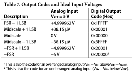
I have an ADC7690
Please note that I use 2.5V as Vref, so values of analog input max/min and LSBs are half the voltage.
Now I have the CDA 18bits in FXP I18.1 format on my FPGA and I want to do some other processing with it. Eventually I want to display my result (signal processing) on my computer and I have to "Scale" my value. The gains from the signal processing are already calculated and the result is multiplied with it giving me correct values. ADC scaling is missing.
Is this correct, that I have to multiply the result by the LSB (19, 08µV) and 2 ^ 17 (to go from I18.1 to I18.18)?
Signal processing:
-Multiplying my ADC signal with an sine/cosine of the same frequency (signal of the ADC is a noisy sinus) = demodulation
-Low pass filter and downsampling: CIC filter followed by average mobile or exponentially weighted moving average
Kind regards
Slev1n
Hello Slev1n,
If you want to display your results, it means that you are no longer on the FPGA. Thus, it would be much simpler convert your point fixed a DBL and then perform the engineering scale.
Michel
-
I have a double precision scalar value to a DAC that represents the current measured in a domestic wind turbine application. This value is harvested in a home made circuit that has a little 'noise problem '. This noise cause fluctuations in the value of more or less 20%, which appears visually in the gauge of the output of my VI as earthquake of the needle. The value of the DAC is read and displayed 3 times per second. I thought that there must be a way to display a moving average of the signal on the last bed N or N seconds that would moderate the noise and the hand shake a little. Tried to play with the built in RMS VI but the data entry type is table and I scalar double-precision. I'm REALLY new to Labview and swimming with ideas of what must certainly be possible but work always on absorbing the incredibly array of features that this software has.
Thoughts appreciated.
You can use Point-by-Point screws.
-
create the differential signal of 6289
Is is possible to create a sine wave of differential on the output of the 6289? And how can I do this.
I created a differential DC 1V AO0 positive and negatives 1V AO1. Then measured on a differential input ADC signal, which is my DUT.
Now, I'm cutting the CMRR and wanr to use the DAQ6289 because I don't want to add another piece of equipment for the test plan.
Any ideas would be appreciated.
Please take a look at this example to see how to generate out of phase sine waves:
http://zone.NI.com/DevZone/CDA/EPD/p/ID/5001
Have a great day!
Daniel G.
National Instruments
-
The purpose of my program is finally take a random signal with a length of discrete and display the fft with Windowing and applied average signal. In the VI attached to this post, I took a sinusoidal signal and treated with an average and not an average. The signal averaging produces an incorrect spectrum.
It would be appreciated if someone could let me know why the spectra of the FFT on average and not average are not the same and tell me how to improve my code to produce the same spectrum of instruction.
A potential problem is that the resolution of frequency of the FFT is function of the number of datapoints in the FFT. Also the relationship of phase between the different segments can vary depending on how your segmentation works and how many segments you define. With window, this can be a problem because the effects of windowing the amplitudes of the sample data at the ends. And with no windowing, it has spectral bleeding.
Mike...
-
Hello
I'm relatively new to labview and programming.
My goal is to acquire potential of the retinal, the signal I get is accompanied by noise and is within reach of micro volt, my goal is to average noise so that I can analyze the real signal (signal without noise).
The incoming analog signal is continuous, but I need to a window of time of 25 seconds alternative to the average value, which means: medium-sized signals of 0-25 s is not an average of 26 to 50 seconds, medium from 50 to 75 seconds and so on...
I started overwhelming with getting a signal from a function generator and averaging the full signal and displays the signal averaged over a second waveform graph. If the VI show all errors I wanted to know if I'm in the right way?
If Yes, then how can I do to average the data to 25 second multiple (for 25 seconds between the starting point)?
I've also attached a diagram of what I expect to see
I was thinking about something in this direction.
You have a buffer limited on the acquisition of your data. If you read fast enough, you will lose data. Then read smaller amounts more often. So I bibliography 1 second with a value of data 25 times.
Because you must connect to both average time, rethinking configure logging it, and just use the TDMS API instead. Do a search in the finder of the example (help-> examples find) for TDMS Wruite time Domain.vi. This is a decent example of what you want to do.
-
Questions about the frequency step response
Hello
I use the Signal Express 3.0. I'm not clear on the transfer functions in step of frequency response with different modes of calculation of the average. What I got from the help file is this H (f) = Sab (f) /Saa (f) which is cross the frequencies on the spectrum auto where is the pulse and b the signal response signal. When the mean quadratic value is used, I wonder if the transfer function becomes greatness of cross spectrum divided by the magnitude of the spectrum of the car. When an average of vector is, everthing is used in complex numbers. He averaged temporal signals, frequency domain signals, or the results of transfer functions?
Thank you very much.
The algorithm to calculate the spectrum is the same in both modes. However, the method of calculation of the average can have a huge impact on the outcome. Mean quadratic value is performed on the spectrum itself, after the calculation. Vector averaging is done on the input signals before the calculation. With an average of vector signals must be consistent (have the same phase) or the result will be bad due to the signal being on average by far.
-
Point by point count in a window
I am a user of labview 8.5 working in the field of aerodynamics - namely laminar boundary layer turbulent transition.
I want to take a signal high-pass filtered, rectify, and then place a window around the remaining signal (equivalent to 10% of the average of the signal not filtered) and count the number of points both inside and outside the window. I can use a histogram for this as in the attached vi, but I need to do an analysis point by point, because the things that pass through the window faster than a length of residence requirement should be considered as turbulent instead of laminar.
To say more explicitly the points above the average of 10% get digitally assigned 1, anything less than 0, but say that part of the signal less than 10 consecutive zero points are sandwiched between two 1 then they need to be addressed as 1 also. Where 10 points in a row to my frequency equals my critical residence time.
I hope I have given you an adequate description of what I'm trying to achieve, could someone direct me to achieve this please? I am not too concerned about the filters, frequency etc. are used at the present time.
Thank you.
Solved. YeeHa!
I want to thank my family, friends (if I have) and sponsors...
-
How to locate the features seen on the block diagram?
Hello world
Please help me with my problem. I read the examples of Labview files. I've seen some icons (for example, in addition to the formula, simulated Signal... etc) on the diagram that I do not know whence these icons (I don't know the name so I can't use search). How would I know the locations of these unknown icons? (average location: simulate Signal is in the analysis of the functions/Express/signals)
Your help is highly appreciated
There is no reason that you would know the name. You, especially as a beginner, should always have context-sensitive help enabled. This will display the name of the function. In addition, if you click on the link "Detailed guidance" in the window, you get a button that says "search on the Palette of functions". On any function, you can also right-click and select visible items > label (or legend).
-
That's what I'm trying to do. I have a file periodic_chan3.bin which is sampled values of three channels of periodic signals in interlaced format. The data is stored in binary format (long of floating point of the double procession) DBL and big-endian representation. I am reading the file and draw all the three waveforms on the graph of a waveform. The data has been saved from time zero, with a sampling frequency of 100 samples per second. Then I scale the x-axis of your waveform graph so it displays the time in seconds.
So I try, on the wave of the chart to create three sets of cursors and cursors to display the average value of each of the three waveforms. The color of the cursor Y for a given signal average must match the color of the display of the waveform on the chart. For example if the graph of the signal is displayed in red the cursor there shows the average of this signal must be red.
What happens when I do not open the file I see a white contour mesh a sine graph, a graphical square and sawtooth chart. I can't seem to trace the three waveforms seen clearly with the three above-mentioned distinct colors. I can't seem to sort correctly and represented as mentioned above.
I would also help with the calculation of the average or expected from each of the three periodic waveforms.
Attached are the files please help. Pgm4 is the VI, and periodic_chan3 contains the data that needs to be sorted. I'd be very happy if somene were able to fix the and submit the changes so I can see how it works. Thank you.
Edit: I get an error that says periodic_chan4.bin "is not a valid extension of an attachment" so I'm not able to uplad it. Is there a way to othe I could download it?
Xtasy26,
In your post you mention that you try to view 3 averages of waveform, however your code is showing that you are broadcast 4 values. This might be the reason why your getting the different forms of data. Instead of an array of all the waveforms 1, then a table of all 2 waveforms and a waveform table 3, you get a mix of all three in each of your waveforms.
To calculate a moving average or mean that it is actually an integrated in the example in BT sound finder called "running Avereage.vi calculation"
You can also view the attachment to see Multiple waveforms channel displayed on a single chart.
-
Output DAQ savings at a lower sampling rate
Hi all
I'm relatively new to labview and all its features. The problem I've seen is that I don't know how to sample a continuous signal again. This is my problem, the assistant LabView DAQ samples continuously at 1 KHz so that the voltmeter is smooth as voltage changes. I don't want to have to record every 1000 data points every second even if in the .csv, so I tried many different ways to "resample" the data at a given rate of about 1-10 Hz.
So far, I tried to use the loop of the timer, I don't know how well it works, and it didn't get me very far. I also tried to set all the values in an array of a specified size (with respect to the sample hz), take the index 0, delete it and begin to fill the table again. This kind of worked, but not at all how I wanted.
Sorry that I can not provide photos or a vi like I changed it so many times he doesn't seem something like what I tried before.
Assistance in this area would be very appreciated,
See you soon
Microtechno
Use a shift to the filenme register.
You didn't post your code so I don't know how you have the DAQ Assistant set up. You would get a writing all data to data acquisition whenever writing file is called. If you want only a scalar value of the DAQ Assistant, doing something as simple as calculating the average of the signal.
-
How to calculate an average mobile signals individual N?
Hello world
My problem is as follows:
With all the samples that I get a table of 64 signals and I would build the moving average of each of these 64 signals.
However, it is very poor to place 64 reentrant mobile medium screws in parallel to it (as shown in the attachment).
That's why I wonder if there isn't a better way to do it?
Each hint is appreciated
Benjamin
Hi Benjamin,
What is "Mobile means" VI: change to accept a table.
In VI it is probably a ringbuffer using a 1 d table to maintain data. Change this into a 2D array to contain values of 64 signals...
-
I know how to program to acquire the signal. But I donot know average and raise my signal as a work of the oscilloscope? What do I have to use "average dc - rms VI" to calculate the rms dc values and/or a waveform of input on average? In oscilliscope, I can choose average 16,32, 64... 512. how to achieve here? There is also a filter of bandwidth in the scope.
The trigger is nothing but looking for a crossing of a certain level. You can use a simple top or a less than to find that. On average, as a scope, you must acquire the signal several times. You can then perform the average for each data point in a loop FOR.
Maybe you are looking for
-
You can assign output by ascending path to an existing project in the logic?
Hi all Never really need to do until today Got a logic project (others 50 titles) I need to assign the output increasing outputs audio. Its the (only) thing that ProTools can do quite easily (cmd & option)... Is it possible to do in logic? Thanks in
-
Cannot find TOSHIBA Web Camera application
I tried to access my webcam but the shortcut was missing from my desk, and I can find is no longer in the list of programs. I checked Device Manager and it says that the webcam is working normally. However, I can only use it online.Any help would be
-
Cannot connect the satellite to LAN
Basically, I can connect to my bb wireless but when I want to use the connection cable at the back it does not connect. It says "trying to connect through WAN miniport PP..." It's just. I have a map of network PA3362U 1MPC. I downloaded the updated I
-
Satellite P20-771: Error Message blue screen after the reinstallation of the OS
I have a portable Satellite P20-771 / Pentium 4 3.40 GHz (800/HTT) / XP Home / 17' with nVidia Geo5700 driver. As I had a few problems with the software, and I reinstalled everything using the supplied CD. Unfortunately the canned computer malfunctio
-
myDAQ new installation self-test fails 88705
"' Problem: NEITHER myDAQ"myDAQ1"- Measurement & Automation Explorer-online devices and Interfaces-online OR myDAQ" myDAQ1 "-online self-test does not work. The error message is "the self-test. has failed. -88705 the specified device is missing... »