Bad analog output help Every_N_Samples-NI-9263 cDAQ-9172 chassis (works with cDAQ-9178 chassis)
Hello
The NOR-9263 analog output voltage geberation works correctly with the cDAQ-9178 chassis but gives wrong result using the chassis NOR cDAQ-9172.
In the attached code example, a single cycle of a sine wave is composed of 40000 samples and came out in the background using Every_N_Samples at a rate of production of 5000 samples per second.
The output buffer size is set to 10000 samples.
Prepare us the buffer writing 10000 samples 1, then write the remaining data in the background using the Every_N_Samples callback.
Bug: Using the cDAQ-9172 chassis, to the 5000 s/s sampling rate with the help of an external field (or through closure to another HAVE), we observed that 1 10000 samples came out twice, followed by the rest of the waveform. The last 10000 samples are never exits. If you are working properly, we would expect to see 1 full cycle of a sine wave.
The bug does not occur with the chassis NOR cDAQ-9178. I use the driver NIDAQmx v9.2.1f0 on Windows XP
The bug does not happen with simulation devices, so you will need to use harwdare real to reproduce.
Please find attached an example of code C based on the example program OR "ContGen - IntClk.c" to reproduce this bug.
Thank you
whemdan,
The MathWorks
Hi whemdan,
By default, DAQmx regenerate old samples if no new data is available. To give the correct behavior, you can:
Use DAQmxSetWriteRegenMode to disable the regeneration (DAQmx_Val_DoNotAllowRegen). In most cases, this is recommended if new data are written continuously in the buffer as the build is in progress.
If you just need to generate 40 k samples, you can write them just all at once, rather than in 10 pieces of k (the code you attached probably is just an example, so I'll assume that you have a reason to write the data into segments in your actual code).
I think the difference in behavior between 9172 and 9178 can if explained by the different way, buffering is set up on each product. The 9172 uses a buffer of 8 k (on the STC2) in all cases (source). The 9178 uses an 8 k of memory buffer (on the STC3) If you use regeneration shipped, but uses the 127 samples FIFO cartridge, if you use no on-board regeneration (source).
Then... on the 9172 8191 samples are immediately transferred to the FIFO. By default, the hardware is going to request new data when the FIFO is less to fill (this is configurable with DAQmxSetAODataXferReqCond). I'm not sure what the transfer data request size is in your case (you can set the maximum value with DAQmxSetAOUsbXferReqSize), but obviously it is bigger than the other 1809 samples that you have not yet sent to the Board of Directors of your first entry. At this point, the pilot will regenerate 10 existing k samples so that sufficient data will be available to meet the demand of data transfer.
The 9178 however use the FIFO of 127 smaller samples so you will not have the same behavior in your case.
In summary, the behavior is explainable by the difference of material. If you want to avoid to regenerate old samples, you should ban the regeneration using DAQmxSetWriteRegenMode.
Best regards
Tags: NI Hardware
Similar Questions
-
Help! Illustrator crashed unexpected when I work with her. Only a reboot allows, after abandoning the preferences. Who knows what bug this is?
If we could, we could make a lot of money, solve problems.
But unfortunately, we can not just from your description. Please give us the details.
What version?
What system?
Third-party plug-ins?
All corrupt fonts?
What hardware is connected?
You have a printer installed?
Font management?
What exactly were you doing when it crashed?
-
Analog output on USB6008 in C ANSI does not work
I tried to program the analog output on a device of USB6008 under MSVC ++ 6.0 with the latest NOR-DAQ 8.8.
The lines of the example of the ANSI C program ' MultVoltUpdates - IntClk.c ' work very well with a device emulator, but not as soon as I try to access the real device of USB6008.
/*********************************************/
DAQmx Configure Code
/*********************************************/
DAQmxErrChk (DAQmxCreateTask("",&taskHandle));
DAQmxErrChk (DAQmxCreateAOVoltageChan(taskHandle,"Dev2/ao0","",-10.0,10.0,DAQmx_Val_Volts,NULL));
DAQmxErrChk (DAQmxCfgSampClkTiming(taskHandle,"",1000.0,DAQmx_Val_Rising,DAQmx_Val_FiniteSamps,4000));During the call to the last line concerning the synchronization setup, an error occurs:
________________________________________________________
DAQmx error: measurements: request the value is not supported for this pro value
Property.
Property: DAQmx_SampTimingType
You asked: DAQmx_Val_SampClk
You can select: DAQmx_Val_OnDemandTask name: _unnamedTask<0>
State code:-200077
________________________________________________________
Is there a work around?
Finally, I want to set unique values for the analog output voltage in a loop.
In commenting on the "DAQmxCfgSampClkTiming" call, no voltage is defined in a "DAQmxWriteAnalogF64" call to handle this task.
Thanks for the tips!
'DAQmx_Val_OnDemand' is not a valid option for "DAQmxCfgSampClkTiming...." and leads to errors of execution, if I put it anyway.
As an alternative, I tried in the meantime:
DAQmxErrChk (DAQmxCreateTask("",&AO_V_taskHandle));
DAQmxErrChk (DAQmxCreateAOVoltageChan (AO_V_taskHandle, dev + ao0 "",""-"))
0.0,5.0,DAQmx_Val_Volts,null));DAQmxErrChk (DAQmxSetSampTimingType (AO_V_taskHandle, DAQmx_Val_OnDemand));
DAQmxErrChk (DAQmxStartTask (AO_V_taskHandle));
DAQmxErrChk (DAQmxWriteAnalogF64 (AO_V_taskHandle, 1, 0, 1.0,-))
DAQmx_Val_GroupByChannel & data_v_out, & writing, NULL));
(data_v_out = 2. ;--> back: written = 1) not--> no measurable output voltageDAQmxErrChk (DAQmxStopTask (AO_V_taskHandle));
--> still no measurable output voltage
Any other idea?
-
I need help for my printer/scanner/copier to work with my computer
I have a problem for my computer to connect with my printer/scanner/copier. I need help!
Hi GraceEverts,
· What exactly happens when you try to connect printer/scanner/copier to work with my computer?
· You receive an error message?
· What is the brand and model of the printer/scanner/copier?
I suggest to check the following items and check if it helps.
To add a printer attached to your computer
To install new or updated printer drivers to update
Resources for the resolution of the printer in Windows XP problems
http://support.Microsoft.com/kb/308028
Printer in Windows problems
http://Windows.Microsoft.com/en-us/Windows/help/printer-problems-in-Windows
To install a scanner or digital camera
Hope this information helps.
-
Help! My operating system does not work with disc
When I installed the DIGITAL SOLUTION DISK for my new EOS 7 d mark ii a window pops up stating:
This software is not compatible with your operating system
I use an old dell works well with XP, is there a way to get around this, I already have photo professional, eos utility etc. of my rebel...
ANY help would be greatly appreciated
Having been forced to upgrade too because I need to process RAW images from the 2 7 using Photoshop, I can tell my updates went well. I bought Win 8.1 & done a clean install on a new hard drive & waited to win 10 out & from my old programs would continue to operate. 10 once was readily available that I made an another clean install on another hard drive as an installation & nine 64-bit (added 16 gigabytes of memory also) & things was great when working in Photoshop, BUT for all those who 7 2 treatment check CR2 what device profile is best. By default, it chooses an Adobe profile that works very well with my other camera files but Standard camera looks better with 7 2 files.
(My computer has provisions for 5 internal hard drives & I 5) I can easily re boot for XP or Win 8.1 if I need to use one of my old programs, but so far, I've been running Win 10 on my office & XP on my laptop.
-
To input analog shutdown when the analog output is completed and synchronization
Hello
I'm trying to get my LabVIEW program to send analog output to a computer and read acceleration using the cDAQ-9184. Chassis output that I use is the NI 9263 and the chassis of entry is the NI 9234. I generate a signal of white noise using LabVIEW Express signal generator.
The first problem I have is the synchronization. I had an old VI that has begun to measure the acceleration just about a second after the entry has been given to the machine. I used the LabVIEW tutorial on how to sync the analog input and output, only to discover that it does not work with two different hunts. Then I found another tutorial that shows how to synchronize different frames between them.
The second problem is the cessation of the LabVIEW program. What I want to do is to generate the signal and then simultaneously send and read the input and output analog, respectively. It is because I don't want a phase difference or any shorter signal for a direct comparison. But as soon as the signal is sent to the machine, I want the entry to stop analog playback and then then the LabVIEW program must stop. I want to be able to choose any length of signal to be generated and stop as soon as the entire duration of the signal has been sent to the machine.
I tried 'DAQmx stop', "DAQmx Timer" and 'DAQmx's task made?' and none of them have worked for me. It is also my first time on a forum posting, so I hope I gave enough information. I enclose my VI as well. The VI shows I read an entry for the analog input voltage, but I am only using this to try to get to the work programme.
I'd appreciate any help I could get.
Thanks in advance
Peter
Hi Peter,.
I have some recommendations for you that I think you will get closer to your solution. First of all, I assumed you meant that you had 1 chassis (cDAQ-9184) who had two modules in it (NOR-9263 and NOR-9234). My next steps are based on this assumption, so if it's wrong, please let me know.
For your first question about the synchronization, the code you provided is very close to what you need. You need to do, however, implement architecture master/slave for startup tasks DAQmx functions. To do this, you can add another frame to the flat sequence structure and put the master start task (input voltage) after the start slave (output voltage) task.
To manage your second question and that the program ends at the point where you, the first step is to get rid of all the logic that you use with the local variable of length of time. Rather than use this logic, just wire the node "task performed?" of "is task performed?" operate to stop the loop. This will cause your loop to stop as soon as the signal is sent to the machine.
I have some other recommendations for you that will increase the performance of your program:
(1) rather than writing on file inside the last loop, you can use the DAQmx Configure Logging (PDM) .vi. You will place this VI between DAQmx Timing.vi and DAQmx Start Task.vi to the task of the analog input voltage.
(2) after the last while loop, you want to stop the task and analog outputs as well with another DAQmx stop Task.vi.
(3) rather than using a local variable for the entrance of displacement and wiring it in the DAQmx Write.vi, you can wire directly from the output waveform of the wave to build function node.
That should help you get started in the synchronization of these tasks.
-Alex C.
Technical sales engineer
National Instruments
-
I bought PS 14 elements of office Depot and after going on with my redemption code download site, it fails. I think the code is bad. Any help?
you will need to discuss with office depot, if there is a code issue.
That said, the redemption code help
-
Slow outputs analog on the cDAQ-9178
My control of the C language application calls the DAQmx API 200 times per second to update some AOs, using the following call:
DAQmxWriteAnalogF64 (taskHandle,
1, TRUE, 0.0, DAQmx_Val_GroupByScanNumber, data, NULL, NULL);
On a system with a single chassis cDAQ-9178 and two modules OR 9264 AO, it works correctly with a task of up to 4 channels. If I add channels to the AO job, the flow slows down below 200 Hz (5 ms). Here are the times:
Chans ms
8 6.8
16 13.4
32 26.9
How can I write 1 sample per channel, more than 32 channels, all 5 ms? It's a control application that meets the entries, so I can't write several samples per call.
Thank you.
-
Hello
Is it possible to program a pwm on an analog output on 9263 CDaq-9174 map? In examples of LabView we on outputs digital. If it is possible can you guide me to an example.
Thanks for your help, Frank
Actually, pour a PWM we must be real-time with digital. However I do not have this material and I am on a regulation of temperature with a period the 2.5 s and a taking your temperature every 1 sec. So I think that this won't be a problem if I don't have much the same time. Screws on the PWM in examples pour outputs digital.
I finally found pour generate that kind of signals on analog output. Perfect no it doesn't serums.
Thank you for your interest in my problem.
Kind regards
-
Read analog output channel value internally
According to this you can read the values of analog output of return without having to physically connect the wires.
By using the technique described in the example given (DAQmx_Read_Output_Internal_Channels.vi) I'm reading a current area of OCCUPANCY on my compactDAQ cDAQ-9174 with a module of analog output current OR-9265.
The output channel is created in MAX and my vi can write values to him without problems
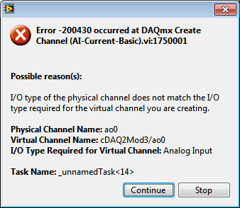
But when I try to create an analog input channel to read the output, an error occurs.
What I am doing wrong?
This is not supported by my hardware?
Or is the example given in the above incorrect link?
The example is 10 years old. Maybe, it does not work in LV2013.
Hi Jocker,
The link was not attached to your message, but I guess that's it: http://digital.ni.com/public.nsf/allkb/CB86B3B174763C3E86256FFD007A2511 as there the example of vi you mention.
The error you are getting is due to the use of the channel for analog output and trying to configure the task as a task of entry. You must use _aoX_vs_aognd as the channel of the task rather than on the output channel. This compares to the ground for the analog output values.
The NI 9265 is not on the list of the C Series modules that have internal channels:
So I guess that the module is not able to compare its output to ground. He would appear in the dropdown of the channel names if available.
Pete
Applications Engineer OR
-
Problem of generation of the analog output on PCI-7342
I use for the control of servo motor with encoder Axis 1 of my PCI-7342 feedback
and trying to out of the velocity of the encoder on the analog output of the axis-2 which is currently not used.
For testing purposes, I pulled out a constant 16383 (half of 32767) to the analog output
through load DAC.flx permanently, but there is no voltage on the map of the motion.
I read
http://digital.NI.com/public.nsf/WebSearch/102BE3EEED8A8B0DC1256EDA0059EC47?OpenDocument
and configure my 2 axis to be a stepper motor. I also tried to disable axis - 2. None of them works for me.
Also, I tried to read the value of CAD using reading DAC.flx right after that load DAC.flx is called.
Correctly, the value was shown on the screen. (See the attached figure)
I'm really bad now. Please, please, please help!
Any possible solution is fully appreciated!
Ron Liou
-
Develop the analog output signal
Let me start by saying that I am a new user of LabVIEW. My experience with LabVIEW is limited to a briefing in which we covered documents in the guide, «Introduction to LabVIEW and Computer-Based measurements» manual the customer Hands-on With regard to what I'm trying to accomplish:
I'm using LabVIEW 8.6, OR cDAQ-9172 and number of NI 9205 and NI 9264 module. I have a load cell that requires a constant supply of 10V to operate. I don't know how to generate this signal or the signal in mV, which is removed from the load to the cDAQ-9172 cell. I tried using DAQ-Express for entry and exit signals. Once I have created two assistants DAQ, I'm not sure what to do next. In addition, the load cell has four sons: green, white, red and black. Green = + GIS, red = + EXC, white = - GIS and black = - Exc. The Red wire is connected to ao0 and the black wire is connected to the COM of NI 9264. the Green wire is connected to ai18 and the white wire is connected to the NI 9205 module ai26.
Any help on this is greatly appreciated!
Yatsco
Hello Yatsco,
Fan of the crows is correct that you would be more successful using a NI 9219 instead of the combination of the PCI module, HAVE / AO. However, it might be possible to use the modules, you should use the load cell, that you try to use, but we need more information on the sensor to say with certainty. A link to form would be preferable.
Assuming that everything would work out with the sensor itself, I would do something like the following:
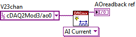
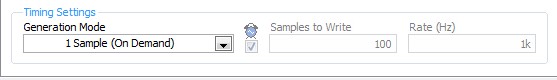
- Configure your analog output DAQ Assistant for output on the 9264 ao0, leave all default settings except for the generation Mode, you should change it to 1 sample (on request).
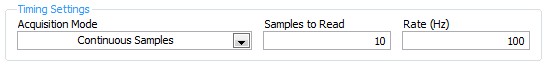
- Configure your analog input DAQ Assistant enter ai18, keep all the default settings again except for sync settings, which should resemble the following:
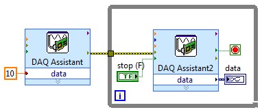
- Your drawing should look like this:
If you do this and you encounter problems with your sensor or its response after the datasheet (or at least the manufacturer and part number), and I'll look into it further.
- Configure your analog output DAQ Assistant for output on the 9264 ao0, leave all default settings except for the generation Mode, you should change it to 1 sample (on request).
-
Variable 0 to 28v analog output of +/-10v on a NOR-USB-6003
Someone here has some thoughts on how I can convert the +/-10V analog USB-6003-NOR module to a low current (under 100 MA) voltage of 0v to 28v input outputs?
I have a legacy Test Set with a few old k potentiometers 20 wired up as shown in the attached diagram. Looking to upgrade the entire facility a little, but I am fighting with them?
I'm open to dumping the 6003 module... do not know what would be a good replacement?
http://sine.NI.com/NIPs/CDs/view/p/lang/en/NID/212385
Thank you
Thanks for you help guys, apparently, I just need to talk through the problem...
I made a mistake on my initial assessment and did not read my meter properly. The legacy circuit is 100uA of reading, I need to pay more attention.

That said, I found a nice guide online for scalability and the polarization of analog circuits: http://www.symres.com/files/scalebias.pdf
I have a circuit prototype built with components specified above, and it seems to work fine. I had to do two things:
(1) I had to re - scale of +/-10V input 0 - 10V
(2) I had to increase my voltage 31V rail Op Amp
I still need to change the values of resistance a bit, but I'm almost the entire range deflection. I'm 0.46V including power - 10V and 27.85V with a + 10V input, and there is no "blind spots", as with the old potentiometers. This is a fast circuit simulation that I whipped out:
-
Simulate the analog output of arbitrary waveforms
Simulate it Arbitrary Waveform VI Express can be used to generate analog signals to the physical channels in analog output mode systems such as the NI 9263? I am trying to use the VI arbitrary signal generator to produce a signal used to excite the magnetic coils.
Why don't you just try and see what happens? As far as I know, it should work.
-
How can I check if the counter entry is synchronized with the analog output?
Hello
I'm working on an application for counting photons. I use two channels of analog output on a PCI-6713 card to send a frame model to a set of XY scan mirrors. I then a photon count unit that emits a TTL signal when the photons are detected as a result of this raster analysis. I then use a surfboard USB-6211 to count the edges on this TTL signal.
I have problems that seem due to synchronization problems. I use the sample AO on the PCI-6713 card clock like the door of my meter on the map USB-6211. I use a trigger to start digital to analog output and a trigger of arms for the entrance to counter early. Is there a way to check that the analog output and counter entry of start of operations at the same time and are are synchronized? I basically want to monitor and compare the ao real sample of the PCI-6713 card clock door signal used by the jury of the USB-6211. I was able to export the sample AO clock and watch it on my oscilloscope, but not the signal from the door of the USB-6211.
Thanks for your help,
Brian
Update... It turns out that there is no problem of synchronization between my meter input and the analogue output. There was a difference of impedance when I connected my unit of counting photons to my USB-6211. This caused an error variable count rate. After accouting for this shift, the problem disappeared.
Maybe you are looking for
-
My screen has changed and text boxes suddenly around all topics and elements of the screen?
Weak black lines/boxes suddenly appear and now all the texts and the major portions of the screen are surrounded by lines. My guess is that it's a setting either FF or Microsoft. If so I have not found. HG
-
I have a virus inches in my file and I lost all my files from the image. How can I get them back?
I have a virus inches in my file and I lost all my files from the image. How can I get them back? Folder was on the desk. So please help me. All files were very important for me. Thank you.
-
Is there any method of rooting without voiding my warranty of U?
I want to the root of my Xperia without invalidating its warranty is there any method if yes then tell me One.And Simple which is the Bootloader what should I do.
-
Could not open the dialog box of .msi files saying find a program to open the file type
In time, I used msi files to install many programs. But I know longer really since then, msi files could not open. Now, I can't open the msi installer, which I had used to install programs. When I click on the msi file, it displays a dialog box sayin
-
Unavailable Smartphones blackBerry media card
Searched and could not find an answer that worked 8310 on 4.5.0.110 with ATT Desktop Manager 4.5.0.16 without Media Manager Device not installed Manager I try to run the driver update and get "a newer version of the desktop software is installed. Pl