Bandpassfilter digital signal
Hey,.
We are supposed to get a signal (made in the first box), then analyze it a little, then scan. So far, it's working.
My problem is the digital filter afterwards. How should I change the filter characteristics?
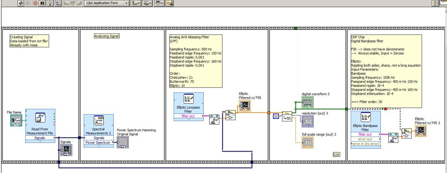
After this filter, we make a filter at 50 Hz (always with binary numbers). I really struggle with this one. My essay is verrrry bad, so I did not take out a picture here.
Thanks a lot for your help!
Hey,.
Thank you very much for your help.
Now, I did not change the binary and figured my mistake at the beginning with the help of a digital filter instead of an analog... =)
Tags: NI Software
Similar Questions
-
No digital signal to headphones Jack S/pdif - Satellite P100-227
I have the Satellite P100-227, I brought a lot of different types of cables and adapters for trying to get a digital signal to headphones s/pdif Jack (the manual says that the helmet and S/pdif share the same socket). I tried a cable optical toslink to an adapter optical 3.5 mm but I can't not all digital audio of this laptop. It seems strange that there are a lot of output video but not audio Digital 5.1?
Why can't they provide a daily normal production as an audio output optical digital toslink?
Hello Chris
I checked the specification for Satellite P100 - 227 (PSPA0E) and it is listed follow Note:
Audio Line out Jack S/PDIF - not availableGood bye
-
How do I configure other digital ports except port 0 of daq 6351 acquisition of digital signals
Mr President.
I can acquire digital signals using 8 lines of port 0, but I have to get the waveform Digital 24-bit. So please tell me how to configure other DIO ports so that I acquired digital signals using these DIO line also
You should be able to create a task DAQmx to read Port0, Port1 Port2. When you read the DAQmx data, you must combine the port if necessary data table.
-
frequency of the digital signal 6009
Hello, how to generate the digital signal with frequency 50 Hz using NI USB-6009?
You can take a look at this:
Can I use a generation of impulses with the counters on the USB-6008/6009 case?
-
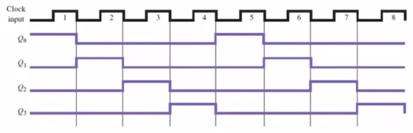
Graph of digital signal using binary numbers.
I need to generate digital signals 4.
I have created a binary number which represents the 4 signals. (I don't know if I integrate it properly).Issues related to the:
1. How can I represents the binary number (4 signals) in a digital chart?
2 - is the right way to generate digital signals?
I need something like this:
Your code is meaningless.
- Why you build an array with one element is there is always only one item?
- Why are you doing floating point operations dealing with whren of integers?
- Your VI does not have a digital signal graph.
Try something like the joint to rotate the pieces...
-
generate a digital signal for 6722 or 6221
Hello
Thanks first for the help I'm already on this forum.
Now, I have the following problem:
I like to generate a digital signal: high for 300µs, low 300 µs, 300µs high, low 300µs, top for about 2 ms.
I'm looking for a solution how to generate this numerical sequence. At the same time, I will read the information via an analog input (if all goes well, I now have a solution for this problem).
I tried to find examples, but I failed. For the moment, I was not able to produce any numeric sequence that worked.
My hardware is 6722 or 6221 - which should be OK with respect to the calendar.
Thank you
-
Generation of digital signals through external trigger pulse on PCI 6251
Sir I want by NI 6251 because I read it has the ability to generate and acquire digital signals on port 0. I want to know that can I generate external clock wave triggering (providing impulses to a line on the acquisition of data)?
Hi Ali211,
Yes, you can use a source of sample for the digital input/output clock external clock. You can connect the external clock source to one of the lines PFI (PFI0-PFI15) and specify the source clock sample like this outer line of PFI.
There are some shipping DAQmx examples that you can start with. Find the examples by clicking Help > find examples in LabVIEW.
DAQmx continually reading digital channel with External Clock
DAQmx channel External digital writing Clock
Hope this helps.
Chris G
-
2 digital signals keep using pxi 6544
Hello
I wonder how I can generate 2 digital signals that continues and I will able to make even phase, or different phase 1/2, or 1/4 different phases. And I need them to be able to their output in any channel (free) my PXI 6544.
I've seen examples of generation (no script), but most of the examples shows just how to generate data in parallel. Generating script I use to achieve this? Repeat for the thing?
Kind regards
Yan
-
How to convert an analog signal into digital signal
Hello
How to convert an analog signal into digital signal, such that each sample of the analogue signal corresponding to 1.2V will be represented as '1' digital signal and other samples of the analog signal (which are not 1.2V) will be represented (converted) ' 0' in the digital signal.
And how to view the wavefroms or graphical indicators signals.
Thank you.
If you have 1000 samples and you want to convert to digital, you get 1000 digital values. Attached, that's what I mean.
-
How to draw a part of a digital signal
Hello, I have a digital signal, and I would like to draw just the 10 first or second 10% of the curve on a digital chart. Could you please help me on this. What is memory, and the effective, faster way to do this.
Thank you
Use GET subset of waveform:
http://zone.NI.com/reference/en-XX/help/371361K-01/lvwave/get_waveform_subset/#Instance7
There is a polymorphic digital version of it.
-
PCI6120-acquire an analogue signal on each edge of a digital signal
Hello
I have the card PCI-6120 and Labview 7.1.
I have a digital signal of the encoder. Am interested in buying an analog voltage on each rising edge of the digital signal. In addition, I have another digital signal (index) between which I wish to make the acquisition.
I tried several options. But I can't get on the digital dashboard via the hardware. Please help urgently. Alternative, I migrated to the acquisitions acquisition high speed analog and two digital channels and deteting change in software programming and then find the analog voltage. Which is heavy and inefficient.
Kindly guide correct programming technique.
Concerning
Marie-Hélène
Hi, Maud.
Thanks for the update and I hope that your well today.
Sorry for the delay but it was the Easter holidays!
Thank you for your congratulations.
I put your sampling frequency at the maximum rate of the clock source (encoder). The DAQmx driver uses the sampling frequency (and the number of samples per channel) information to perform various calculations and set sizes for the buffer.
If you set it too high, nothing will happen-guests still just on each edge of the unit receive. If you set it too low, your stamp could be too small and you may lose data.
Hope this helps,
-
MyDAQ - generation of a digital signal and display on an analog waveform graph
Hello
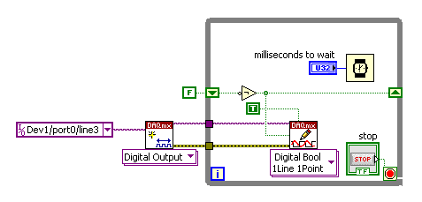
I use the MyDAQ OR generate a digital waveform with a Frequency adjustable. This is implemented in a program, I already wrote it, which generates a TTL 'like' impulse out of the sound card. I display the result on a graph of analog wave form, and I would like to be able to display the digital signals generated by the myDAQ on the same graph. (Not in the same time, one or the other, activated by a button). I've been messing around with tables and conversions, but I can't really do with all this.
It's the vi, I did to generate the digital signal of frequency with MyDAQ. Any suggestions on how to do this if the following is false, would be great too, as I just got the MyDAQ a few days ago. I think there must be a better way, but it's the best I could come up with so far.
Hi Jonny,
The General logic, that you use to create a digital pulse train is very good. This VI you wrote should work and create the pulse train based on timing of software (which is fine because you have not DIO clocked by the material on the myDAQ anyway). However, it is generally advised to start the DAQmx task just before your time loop and then disable the task after the while loop when you press stop.
For reference, there are a few examples of good enough LV that I recommend you watch too much for this application. If you try just to create a digital pulse train, the example Gen dig Pulse Train - Continuous.vi is a good example that uses a counter to create a digital pulse of your desired frequency train. It is generally the preferred method to create a pulse train, if you have equipment available to do (the myDAQ there a meter). Otherwise, there are a few examples DIO who write continuously in a digital line / port.
If you are unfamiliar, you can find the examples by clicking Help > examples find... into LV then navigate to hardware input and output > DAQmx > generating digital impulses or the digital generation.
Also, here is some additional information on the myDAQ and its counters:
Hope this helps.
Chris G
-
time extraction of the digital signal
Hello
If I have digital signals from optical barriers and to extract the time (for a body that passes these 2 obstacles) how can I retrieve this day there using Labview.
THX
I have chata,
Thanks for the answer, and I hope that your well.
Here's an example I've done for a client, eager to discover the time of a flat section of its waveform.
In your case, you must make a detection of pic on both codes, then less locations and a few x with the number of the sample to get the time.
Let me know what you think.
Kind regards
James.
PS Sorry code is a bit hasty.
-
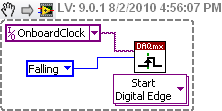
How to generate a digital signal on a negative slope of the clock?
Hello
I need to get out a finished length of the Digital pulse which will begin on request to the negative of the clock slope import (or export).
I try to get the clock, exported or imported, but in any case, I can trigger output signal on the negative slope.
What is the trick?
Thank you
Pawel
What camera you use to build your digital signal. What is the source of the clock? You can attach your vi? Normally, there is a function of data acquisition for configure the trigger where you choose the source of the trigger and the trigger slope (rising or falling), should be declining to a negative slope.
-
Acquire 2 digital signal of custom scale (Engg units)
I am a newbie to the world of DIO.
I write a VI to acquire 2 digital signals. one of a load cell and others for engine rpm (legumes). I need acquire these two signals and then convert them to engg units using the custom scale and write it in a txt file with timestamp.
Please suggest the best ways to accomplish this task.
Thank you
DAQG
Look at the examples on DAQmx in the finder of the example.
You would not really acquire 2 digital signals. You would acquire an analog signal of the load cell. A digital acquisition or against, this is what would make you the acquisition of the motor. Looking for analog and the counter measures in the finder of the example. Some of the example should show you how to apply the custom scale.
Maybe you are looking for
-
It is not possible to install Adobe Flash player 11.1
It is not possible to install Adobe Flash player in the browser, it works without problem?
-
Satellite L500-1XL - high CPU usage all the time
Hi all I've owned the L500-1XL for over a year now and I recently encountered a new problem: for the last few weeks, the laptop everything can become very, very slowly. Everything I do, the laptop freezes and may stop responding for a few minutes at
-
external reference for USB-5132
Hello I have a few questions (I hope) General on the use of an external reference on our USB-5132 digitizer clock. We want to block for the other oscillators in our system, which are currently locked to a single reference of 10 MHz. If I connect ou
-
Help, please
-
Precision 7510 outputs to a single monitor through E-Port Plus Advanced Port Replicator
Someone had problems with accuracy 7510 output only via an exit DisplayPort on the E-Port Plus Replicator of Advanced Port? Our Organization has recently begun to introduce units of precision 7510 to our employees, and we see that they only will be o