behavior of 3D mapping sensor
Hello
I'm using Labview 8.5 to work. As you may already know, versions 8.6 prior have a 3D sensor mapping feature, which can help a lot with the development of a project.
However, I need to explain how it works in order to have authorized a purchase or an update of our LabVIEW liscense, to obtain a more recent version. We already have a source program closed for sensor mapping, we don't know even what technical mathemathic uses to map data, or can modify it to fit our needs.
Just knowing the names of the techniques of interpolation/extrapolation/one other-math or indecipherable are used to map between the two parties, the model and sensors, would be sufficient.
Thanks in advance.
Hi tunario
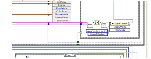
It uses an algorithm of linear interpolation basis, and if you want to have access to interpolation VI sensor mapping Expresss VI uses you will need to follow these steps:
- Place a sensor mapping Express VI on the block diagram
2. right click on the VI and select open the front (this will convert the express VI format so we can view the block diagram)
3 inside of this VI, open the Update Mode.vi
4. in the top of the structure schema-block case page, you will find a Subvi, called interp.vi5. This is the VI which is used to interpolate values for the mapping.
I hope this is enough and if you need anything just ask.
Brenda
Tags: NI Software
Similar Questions
-
Sensor mapping VI Express performance degrades over time
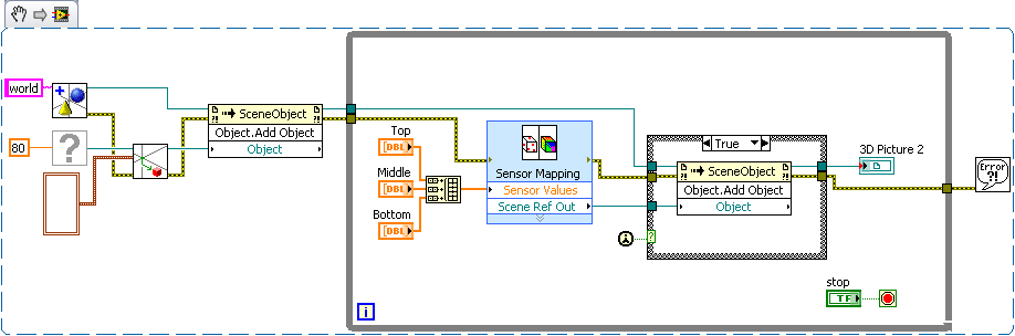
I was trying to make a visualization 3d of some data from the sensor. I did a template and was able to use with the 3d photo tool sensor mapping Express VI. Initially, it seems to work perfectly, and I started to increase the scene with other objects to improve the user experience. Unfortunately, I think I am doing something wrong, at this point. When I add the map sensor object to other objects, something like a leak memory occurs. I'm starting to experience the degradation of performance almost immediately.
I don't know how I should add to better add in reference of the Map sensor to the scene as an object. Normally, I create these child relationships first, before doing anything to objects, beyond creation, movement and anchorage. Since the map sensor output reference is available only AFTER the express vi run. My compromise solution, currently, is to have a case statement of controlled by the constant "First Call". So far, the performance seems to be much better.
Does anyone have a better solution? Am I even manipulate these objects the way the t community - it?
EDIT: Included the vi and stl files.
I agree with Hunter, your current solution is simple and effective, and I can't really see a much better way to accomplish the same task.
Just as a side, note the simplest and the easiest to force the order of execution is to use the error on the functions and the screws in your block diagram. From here with an example based on the VI VI you have posted. (If you paste the image into your drawing, you can make changes to the code)
Given that you have expressed an interest in the documentation links to 3D image controls, I did some research and found a few articles that might interest you. There is nothing terribly complex, but these should be a good starting point. The first link is a URL to the thread of research, so you can get an idea of where this that I'm looking. You will get more hits if you search of ni.com rather than ni.com/support.
http://search.NI.com/nisearch/app/main/p/q/3D%20picture/
Creating a scene in 3D with 3D picture control
Configuration of a 3D scene window
Using the 3D picture control 'Create height field VI' to convert a 2D to 3D image textured heigh...
With the help of lighting and effects of fog 3D Picture Control
3D picture control - create a moving Texture using a series of Images
-
PCI-6221 behavior off the power
Hello
A card PCI-6221, tension of the PC is out of snap-ins:
When I inject a voltage (5V) input ana on the map, this tension is copied on the other analogue channels.
Room I turn on the PC, and 6s after, injected tension is more copied on the other tracks of ana.
What is the normal behavior of the map?
Thank you pour your answers
Hello Cedric,
The behavior of the card when it is turned off is not defined. What is it you have a problem in your application?
When you area PC, this one seems to provide power to the bus PCI 6 seconds after it starts, which explains why the map then adopts its operation.
The best advice I can give you is to respect the configuration/connection of analog input (manual page 58 Chapter 4-14 M-series cards). About the card, if it works properly when the PC is turned on, and that the connection am well the guide, there is every reason to be reassured.
I wish you a good day,
Marc-Junior
-
Intensity on a model 3D mapping
Hi all
I am doing a project which corresponds to the intensity in some positions of a 3D model.
I've tried sensor mapping an Express VI. It's exactly what I want to do. But I have to change the configuration of the double click on the VI in block-scheme, and I can't limit the range of intensity one probe.

So, I want at least to change the model or the positions of the sensors on the front without stopping the program and opening in the block diagram. And it will be perfect if I can limit the intensity range.
Please help me solve this problem. It is not required to use the map sensor.
Thank you very much!

No, the only way to change the configuration of this particular VI is by double-clicking on it when the VI is stopped. If you had a list of values that you want to use, you can create multiple instances of the VI, and each of them would have a different configuration. You can then place them in a case structure and then use a control on the front panel to select which configuration you want to use. Basically, you'd have a different configuration for each case. It's the only way I can think of that would allow you to work around this problem.
-
I created the current code that takes an address and geocoded location with a marker. I now need to find the elevation at this place and get an error during execution in the output window of: "TypeError: Error #1009: cannot access a property or method of a null object reference."
It is on the line that says: "elevator.loadElevationForLocations (locationArray);". Thank you for any help or advice.
import com.google.maps.services.ClientGeocoderOptions;
import com.google.maps.LatLng;
import com.google.maps.Map;
import com.google.maps.MapEvent;
import com.google.maps.MapMouseEvent;
import com.google.maps.MapType;
import com.google.maps.services.*;
import com.google.maps.overlays.Marker;
import com.google.maps.overlays.MarkerOptions;
import com.google.maps.InfoWindowOptions;
import com.google.maps.controls.ZoomControl;
import com.google.maps.MapOptions;
import flash.events.*;
import flash.display.*;

var map:Map = new Map();
map.key = "your_api_key";
map.sensor = "false";
map.setSize(new Point(600, 400));
map.addEventListener(MapEvent.MAP_READY, onMapReady);
this.addChild(map);
var elevator:Elevation;

btnRun.addEventListener(MouseEvent.MOUSE_UP, onReleaseHandler);

function onReleaseHandler(event:Event):void {
        // Geocoding example
        var geocoder:ClientGeocoder = new ClientGeocoder();

        geocoder.addEventListener(
          GeocodingEvent.GEOCODING_SUCCESS,
          function(event:GeocodingEvent):void {
          var placemarks:Array = event.response.placemarks;
          if (placemarks.length > 0) {
            map.setCenter(placemarks[0].point);
            var marker:Marker = new Marker(placemarks[0].point);

            marker.addEventListener(MapMouseEvent.CLICK, function (event:MapMouseEvent):void {
                marker.openInfoWindow(new InfoWindowOptions({content: placemarks[0].address}));
            });
            map.addOverlay(marker);
               map.setZoom(18,true);
               trace(map.getCenter());
               txtLatitude.text = "Latitude: " + map.getCenter().lat().toString();
            txtLongitude.text = "Longitude: " + map.getCenter().lng().toString();

               /*Get Elevation*/
               elevator.addEventListener(ElevationEvent.ELEVATION_SUCCESS, showElevation);
               elevator.addEventListener(ElevationEvent.ELEVATION_FAILURE, onElevationFail);
               var locationArray:Array = new Array();
                 locationArray[0] = map.getCenter();
               elevator.loadElevationForLocations(locationArray);

               /*Calculate Gravity*/
               var gravity:Number  = -(978032*(1 + .0053 * Math.pow(Math.sin(map.getCenter().lat()/57.3),2) - .000024 *Math.pow((Math.sin(map.getCenter().lat()/57.3)),4)) - .3086 * 1300)/100000;
               trace(gravity);
               txtGravity.text = "Gravity (m/s/s): " + Math.round(gravity*1000)/1000;
          }
        });
        geocoder.addEventListener(
               GeocodingEvent.GEOCODING_FAILURE,
               function(event:GeocodingEvent):void {
                 /*Alert.show("Geocoding failed");*/
                 trace(event);
                 trace(event.status);
         });
            geocoder.geocode(txtAddress.text);

     }

     function onMapReady(event:Event):void {
        map.enableScrollWheelZoom();
        map.enableContinuousZoom();
        map.addControl(new ZoomControl());
          map.setMapType(MapType.SATELLITE_MAP_TYPE);
     }

     function onElevationFail(event:ElevationEvent):void {
            trace("Failed");
     }

     function showElevation(event:ElevationEvent):void {

          trace("Elevation");
     }
You can create altitude AFTER your card is initialized (in your case, only based on onMapReady and its subsequent function calls).
-
NEITHER 9213 acquire data of the CJC in mode Scan interface
Hello
I would like to ask if somehow possible to acquire data of CSF (voltage or temperature) of map sensors NI 9213 uses the cRIO (9076) scan interface mod or I have to develop my app using the FPGA?
Why do I need data CJC aims that I use thermocouple type L which is not supported by the card and so I need to have the thermocouple voltage and temperature of the CCM in order to calculate the temperature measured.
Best regards
Hello
The only way you can do this develops the FPGA application.
Why not use a different type of thermocouple?
Kind regards
Ion R.
-
6534 PCI for digital output finished generates a continuous output
Hello
I use 6534 PCI for my application, where I generate a digital output, a model finished variable length in a continuous loop. the code runs without error, but I'm not able to justify the behavior of the map. I intend to use the code inside the while loop as a Subvi and if I change the 'command' at the entrance table during each call to the Subvi, the output should vary according to the directives of the entry of the 1 d array.
But this is not the case, the loop displays the previous value that has been given to Scripture DAQmx. If the control panel is changed the output instantly does not change. It takes a while before the actual output changes. The length of the array command I give is also 88 & 133. When I realize that the output is wrong, I disable the DAQmx write vi by a structure of the case, I would expect an error that the output buffer is empty, but rather the old value is generated whenever the start Daqmx vi task is exectuted without.
My tax any problem is that the output buffer is not get replaced with the new value, but I'm specifyng the size of buffer, performing a registration every time and start the task, waiting until the task is done and the task stop. Each stop & writing should delete and empty the buffer, but I did not understad what goes wrong.
Also, I thought that maybe that orders are put in queue up in the output buffer, acual generation is not as fast as the call of the DAQmx write & start, but if that's the case then even if I stop the vi the generation should be until the buffer is empty, but that doent happen VI, break breaks of generation. the number of iterations is equal to the generated models. If anyone can help as to what could be the problem? fi
nd code attached below.
Hello
If I understand the problem you are experiencing, then the reason for the typical behavior when you run the VI, it is that you are not clearing the DAQmx task whenever you intend to go for a fresh DIO write. You stop just the DAQmx task that seems however to clear the buffer on board space.
With this post, I am enclosing a VI of the sample that should work according to your expected behavior. You can even call this VI as a Subvi and can use it to update the DIO port with a digital model of variable length fees. Another fact that I would like to point out, is that, once you have initalised one table, it is not possible to reduce the length of the array. You can only increase by adding new elements. According to your needs given that the digital model that needs to be updated will be of variable length, each time you cll the Subvi, you must create a freash of appropriate length and feed it as input to the Sub - VI. Inside the Subvi, according to the length of this array of entry appropriate buffer space is allocated.
Do trust this solution help solve you the problem, otherwise do not hesitate to go back.
Best regards,
Sagar G yapi | Application engineer | National Instruments - India
-
High CPU on ASA 5585 SSP IPS10 X
Hi there
Just got my attention on this other discussion on hign cpu ips module - we have a set of 5585 x where ips (quad core) module shows very strong use of processor - 75% - according to the IME 4 carrots 3 run 100% and the last is completely idle. The IPS module is not yet in use and also configured with management ip and automatic update (and with a load of 0 control) is in default configuration.
This is normal behavior for him?
It is the engine use 6,0000 E4 with signature 693,0
Hello
It is normal behavior for an IPS sensor.
In the engine sensor E3 or above the IPS uses a different algorithm for the management of his idle time and spend voting more time to reduce the latency of packets. This translates into higher than previous versions reported CPU usage.
You can view these statistics by using the command 'display the scan statistics-engine '.
Also, the sensor running version 7.0000 E4 5,0000 E4 (or later version), you can check the load percentage value Inspection displayed by the command "Display inspection-load" in its place.
Thank you and best regards,
Cyril Shankar
-
100% high CPU load and memory usage
Hi all
My company bought a new appliance IPS 4510 and after initial installation, I see that the CPU load and memory is 100%. The device is not in a production network. Is this normal or there is a hardware problem? Enjoy a Counselor about it.
Concerning
Christine
Hi Damien,.
It is actually normal behavior for an IPS sensor.
To measure the actual load of an IPS sensor, you will want to monitor the "percentage load treatment" of the analytical engine that processes all inspection processing for the sensor.
You can view these statistics by using the command 'display the scan statistics-engine '.
Also, the sensor running version 7.0000 E4 5,0000 E4 (or later version), you can check the load percentage value Inspection displayed by the command "Display inspection-load" in its place.
Hope that answers your query.
Cyril Shankar
-
Why stage Builder creates constantly new instances of nodes?
Hello
I thought I had a simple idea to create a control that would allow me to recover a part of the behavior of a component of the map. It's all of the control:
import javafx.beans.property.BooleanProperty;
import javafx.beans.property.SimpleBooleanProperty;
import javafx.beans.value.ChangeListener;
import javafx.beans.value.ObservableValue;
import javafx.scene.Node;
import javafx.scene.Parent;
import javafx.scene.layout.StackPane;


public class Card extends StackPane {
    private final BooleanProperty active = new SimpleBooleanProperty();
    public final BooleanProperty activeProperty() {return active;}
    public final boolean isActive() {return active.get();}
    public final void setActive(boolean active) {this.active.set(active);}


    {
        visibleProperty().bind(active);
        managedProperty().bind(active);


        active.addListener(new ChangeListener<Boolean>() {
            @Override
            public void changed(ObservableValue<? extends Boolean> observable,
                                Boolean old,
                                Boolean active) {
                System.out.println(toString() + " active changed to: " + active);
                if(active) {
                    Parent parent = getParent();
                    if(parent != null) {
                        System.out.println("Parent is: " + parent.toString());
                        parent.getChildrenUnmodifiable().forEach(Card.this::deactivateIfCard);
                    }
                    else {
                        System.out.println("Parent is null.");
                    }
                }
            }
        });
    }


    private void deactivateIfCard(Node node) {
        if(node != this && node instanceof Card) {
            Card card = (Card) node;
            card.setActive(false);
        }
    }
}
The idea is simple enough; expand StackPane, add an active property, bind the visible and managed component properties to the property active, and, whenever the active property is changed to true, browse the sibling nodes by disabling brothers and sisters who are also the type of card.
However, this does not work with the generator from the scene. While trying to debug, I created an ExtStackPane:
import javafx.collections.ListChangeListener;
import javafx.scene.Node;
import javafx.scene.layout.StackPane;


public class ExtStackPane extends StackPane {
    {
        getChildren().addListener((ListChangeListener<Node>) c -> {
            System.out.println("ExtStackPane children change: " + c.toString());
        });
    }
}
It doesn't save that list change events. However, I was very surprised by the exit when you work in the generator from the scene. I added both controls the generator onstage and did the following:
0) added an ExtStackPane
(1) added a map to the ExtStackPane
2) added another card at the ExtStackPane
(3) adds a label the first card
(4) added a label to the second card
5) changed the text of the first label Hello
6) changed the text of the label of second in the world
(7) set the first card to active
(8) the value of the second card active
I get the following result:
1)
ExtStackPane children change: { [Card@5b9067b3] added at 0 }


2)
ExtStackPane children change: { [Card@6b6328bd] added at 0 }
ExtStackPane children change: { [Card@6aca8cc5] added at 1 }


3)
ExtStackPane children change: { [Card@3b7bc340] added at 0 }
ExtStackPane children change: { [Card@1879819e] added at 1 }


4)
ExtStackPane children change: { [Card@60ffed67] added at 0 }
ExtStackPane children change: { [Card@64955a14] added at 1 }


5)
ExtStackPane children change: { [Card@5dc96bc4] added at 0 }
ExtStackPane children change: { [Card@40667c26] added at 1 }


6)
ExtStackPane children change: { [Card@164770fa] added at 0 }
ExtStackPane children change: { [Card@7decebbf] added at 1 }


7)
Card$1@f4f4850 active changed to: true
Parent is null.
ExtStackPane children change: { [Card@27442c8b] added at 0 }
ExtStackPane children change: { [Card@643d810e] added at 1 }


8)
Card$1@4877c67b active changed to: true
Parent is null.
ExtStackPane children change: { [Card@7e8a473e] added at 0 }
Card$1@2b4497c1 active changed to: true
Parent is null.
ExtStackPane children change: { [Card@5df6c8cc] added at 1 }
This is what things look like in the generator from the scene:

The scene generator recreate the entire hierarchy whenever I make a small change? Here's an app that does the same thing as the manual steps that I performed in the stage Builder:
import javafx.application.Application;
import javafx.scene.Scene;
import javafx.scene.control.Label;
import javafx.stage.Stage;


public class CardApplication extends Application {
    @Override
    public void start(Stage primaryStage) throws Exception {
        ExtStackPane stackPane = new ExtStackPane();


        // 1
        Card card1 = new Card();
        stackPane.getChildren().add(card1);


        // 2
        Card card2 = new Card();
        stackPane.getChildren().add(card2);


        // 3
        Label label1 = new Label();
        card1.getChildren().add(label1);


        // 4
        Label label2 = new Label();
        card2.getChildren().add(label2);


        // 5
        label1.setText("Hello");


        // 6
        label2.setText("World");


        primaryStage.setScene(new Scene(stackPane));
        primaryStage.setTitle("Card Application");
        primaryStage.setWidth(600);
        primaryStage.setHeight(400);
        primaryStage.show();


        // 7
        card1.setActive(true);


        // 8
        card2.setActive(true);
    }
}
The output when executing the above is:
1)
ExtStackPane children change: { [Card@6dfaa767] added at 0 }


2)
ExtStackPane children change: { [Card@6aa2c411] added at 1 }


7)
Card$1@1abf7511 active changed to: true
Parent is: ExtStackPane@41993867[styleClass=root]


8)
Card$1@5733cd2 active changed to: true
Parent is: ExtStackPane@41993867[styleClass=root]
Card$1@1abf7511 active changed to: false
The behavior is obviously very different than when I work with control in the generator from the scene. Can someone explain to me that event giving rise to the stage to change the behavior of my map control so much? My map control breaks some I'm not aware of one or more rules?
I think you're confused about what makes SceneBuilder.
SceneBuilder is a design tool, used by the programmer (not the end user) to generate the part of the code that is used to run the application. (Specifically, it generates the FXML code which is analysed by the FXMLLoader to create and configure objects that are usually part of the graphic scene.)
When you use SceneBuilder to create the code, it generates a model of what the user interface will look like, if the generated FXML should be loaded and displayed. This model is not meant to be an identical vision of what will be the end user, but a help to you, the programmer, to generate the code that you want to.
So, for example your accordion/TitledPane in the layout of the poster than SceneBuilder, the * selected * titled pane is always expanded. This allows you to drag and drop objects inside and set it up in other ways. If you clear the checkbox "extended" in the properties pane, then it remains extended in the model so that you can continue to configure it. However, this property is not ignored: the State of these boxes is respected in the FXML file that is generated. So when you click on 'save' in SceneBuilder, the fxml generated will contain TitledPane extended element = "true" If the box is checked and expanded = "false" If the check box is cleared. (SceneBuilder will of course also applied the rule that only TitledPane in the accordion can be increased.)
Similarly, for your control customized, you should be able to implement and SceneBuilder displays the 'active' property in the box. If you disable this property, if active = false, which will be respected in the fxml and when you run the active application will be set to false and so by your liaison, visible is set to false and the component is not displayed. But the comp in (of course) SceneBuilder always displays your component, because it would be extremely difficult for you to configure a component that did not appear in the programming tool.
In fact, there is no real reason for SceneBuilder create all the objects that you set up at all. He could just trying to figure out what they look like and render a representation of them on a canvas, for example. It's probably much (much) harder than instantiating them and the authors of SceneBuilder apparently chose to write SceneBuilder in a way that re-instantiates the controls several times. But this has absolutely nothing to do with what happens when you run the application and it is no logic at all to compare the two.
-
Configuration sensor mapping VI window freezes every time that a. STL file is loaded
The sensor mapping VI gets frozen every time I load a .stl file and the black screen does not appear any model of representation. On the other hand, the same model in a .wrl format works very well. Could someone help me with this problem?
I have the evaluation version of LabVIEW 2010 SP1.
Thanks in advance.
Hi uxpro
I think that you can have your .stl file in a binary format instead of an ASCI format, perhaps that is the reason of the gel
Concerning
Julio Mena
-
I'm trying to use a 3D picture control to draw a simple geometric object (a cube) and then draw the measures that took place within this object. So, basically, a field of 4 d. I read the workout at http://digital.ni.com/src.nsf/websearch/624DF39F2EBF492E8625738A006F0D42?OpenDocument&node=203014_us who showed me how to create the cube. I also found this example of sensor mapping http://decibel.ni.com/content/docs/DOC-2059. It's about what I want to do, but I don't have a template file. Is there a way to add values of sensor for a 3D picture control when you do not have a .stl or .wrl file? Does anyone have examples? Thank you.
Hello
You can return to the example of trace of 4 d following the link:
Plot of 4 d, a level 3 data from freedom from time
http://decibel.NI.com/content/docs/doc-9291It seems the task you are trying to achieve? This example uses additional features of the 3D picture control palette, as opposed to the VI of mapping of the sensor. To properly place and restore the data from the sensor, we would need to generate a load of basic with the sensor mapping VI model file.
Please post back you have any additional questions.
See you soon!
-
Behavior of reading-writing-support-map-scheme in combination with local-schema
Hello
I have the following questions related to the distributed cache as defined below:
1 if I start putting an unlimited number of entries to this cache will I run out of memory or the local schema has a default limit size?
2. What is the strategy of eviction by default for the local schema?
< distributed plan >
< name-system > < / system-name >
< service name > simple_service < / service-name >
< support-map-plan >
< reading-writing-support-map-plan >
< internal-cache-system >
< local plan > < / local plan >
< / internal-cache-system >
< dumps-plan >
schema < class >
> class name < SomeCacheStore < / class name >
< / class-system >
< / dumps-plan >
< / reading-writing-support-map-plan >
< / support-map-plan >
< / distributed plan >
Best regards
JarekHello
The default value for the timeout is zero which means does not expire.
http://wiki.tangosol.com/display/COH34UG/local-scheme
Thank you
Tom -
Map I/O behavior when PC loses power?
Hi all
I'm working on an existing Labview application that uses a number of fieldpoint i/o modules. IO modules measure voltages and currents on a system of current alternative and contactors etc. nearby. I am worried about what happens when you run a Labview program and the PC loses power? The outputs go to a defined or random State?
If a PC using modules e/s always being on a UPS?
Thanks for any clarification,
Sean
Using a controller of fieldpoint or fieldpoint network module?
You ask about knowing if a PC loses power. But your concern on when the network module or controller loses power?
If your PC loses power, but not the network/controller module, then all output should stay at their last good value. Basically, you have removed any communication providing updated data.
If the network/controller module loses power, then all modules IO would lose power. But if the power comes back, then modules e/s would go to their default start state until the PC would communicate a new value for them.
You should also watch the watchdog functions. I know a controller fieldpoint has them, but I have not worked with a network module.
Like Thoric said, it is essential for safety, then the PC and/or fieldpoint controller/module must be saved with an inverter. Factor in the code so that it can detect the loss of power and set all values and exits in your system settings of security before the UPS battery would die.
-
USB-6211: analog input signal affecting another of the same map AI
Hello
I use the DAQ-nor-6211 map and DAQmx features to read a hammer and a signal of the accelerometer and then use other LabView functions to make the FFT of these analog input signals. However, it seems that the analog inputs where the hammer and the accelerometer are connected generate a kind of noise or influence in other entries of this data that is not connected to any other sensor acquisition board.
I've had different experiences in order to check if the problem is with reading the card: put the accelerometer and hit the dog in another table where the DAQ card table was located (to avoid the vibrations on the map and a possible noise), ai1 entry was logged on the differential mode on the dog and the ai4 of entry is connected to the output (z axis) of the accelerometer. The other 2 ai2 and ai3, entries that can also be read by my LabView program, are open (i. e., any other sensor is connected to the card). When the structure where the accelerometer is located is struck by the hammer, the signal of ai2 ("x axis" seen in the first attached document) has a curve (on the time domain) which initialize almost at the same time that the hammer and the a3 of entry has a weak signal, but with the swing as well as the signal of ai4. The document "hammer ai1 + z_axis connected_ _x_axis disconnected ai2 + y_axis ai3 ai4" images that I captured the chart created in LabView. On these graphs, it is possible to check on the FFT the ai3 signal and ai4 has the same behavior (with different intensities), and enlarged figure of time domain image, we can see that the signal of ai2 increase almost at the same time of the signal of the hammer (ai1). The signal picked up by the sensors are probably creating a sort of noise on open entries ai2 and ai3.
Another experiment was conducted to check if the signal from a single entry that may affect the signal read from each other near the entrances: the DAQmx task Create channel had a physical channel has changed: ai3 entry has been modified by ai7 (maintain the same connection mode: differential), and the results are visible on the second attached document. In the graphs obtained in this experiment, it seems that the entrance of the hammer (ai1) affects the signal of input ai2 and ai7, which are not connected. And the ai4 signal does not seem to influence the other inputs, because he has a different curve on the graph of the FFT.
The same experiment was conducted using the CSR connection (change threads and create the DAQmx Channel Configuration), but the results were the same as those found using differential connection.
Finally, if the output of the accelerometer is connected on the ai2, the signal of the other open entries ai4 and ai7 seem to be affected by the signal of the accelerometer on ai2 (last document attached).
Could you tell me if the problem I encounter is caused by the DAQ card with this information that I gave to you? And if the answer is Yes, do you know if there is a way to avoid this noise create in one entry on the other hand, it please?
Thank you
Maybe Ghosting or crosstalk? Just an idea.

Maybe you are looking for
-
Trying to update my video player, I clicked on 'file' and then download it and I got was a full window of the computer language without option "run".
-
In the latest updates to my browser 30.0. I now have Web sites do not show my password box so that I can enter my password. Still in the browser no problem when I try websites. It of not all Web sites but select some that I visit most often. I think
-
When the latest version of Firefox has been installed it gave me a message that the McAfee software was not compatible and so I have more protection against viruses. She added that when it became compatible I would be informed. I cannot afford to be
-
How can I increase the size of web page?
I just downloaded Firefox 3.6.6. & after I restarted my computer, all of the pages that I went on the internet are now very low. I have a big screen and had no problem with the previous version of Firefox. The web pages were all big. I know you can c
-
Dear, Sir my laptop has built-in camera and my laptop model is HP dv6-6b25tx, which one does not work on Skype, facebook etc and in my pc, imaging device driver is missing. How can I solve the problem of my webcam. Please give the link for all the dr