Binary indicator
Hi all!
I have a binary number, say 00000101. I would like to indicate that every bit of correspondent led on the front panel.
So in this case, it'll be led0 and led2 on.
How can I do?
Hi John,.
Use the function 'Boolean array number', that is in the range of Boolean function...
Tags: NI Software
Similar Questions
-
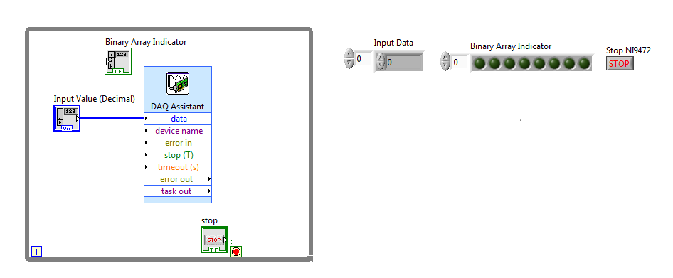
Binary indicator for digital output device
This probably simple question for most people, but there is always a first time to do a new thing/thing we have ever done.
I NI 9472, which is a digital device of the supply, I have no problem to control using LABView to produce the result (line 00000000). I would also like to have some information on the computer screen using the LED matrix. I am able to create a binary table indicator, but fail to connect the decimal point of entry to the binary table.
Please help/provide a few tips, it is appreciated.
Number of table Boolean Boolean palette.
-
Strange question, while calling the DeviceInfo.getBatteryStatus () function
I don't know when and how I can post pictures on this forum...
OK, I guess that this must be a bug in the system, because when I call getBatteryStatus function without USB connection I receive a normal status, however, when connecting to a USB device (include AC, external and computer) I received only a State, 5, an odd number value!
I need your help, so! ~
See the API:
Returns:
Combination of masks BSTAT_xxx of this class.The returned value is a binary indicator pattern. 5 would mean "4 is true, also applies to 1.
If you need more information about this mechanism, you can google binary indicator. -
How to test the weather device is roaming or not?
Hi, we have a requriement that we check the weather, that the device is roaming or don't use not rim api.
so any body can help me please in this area, which has the code to know weather device is roaming or not using not rim api?
You should check the bitmask returned by RadioInfo.getState (). For example, in this way:
boolean isRoaming = (0 != (RadioInfo.getState() & RadioInfo.NETWORK_SERVICE_ROAMING));
In addition, pay attenation that are NETWORK_SERVICE_ROAMING and NETWORK_SERVICE_ROAMING_OFF_CAMPUS. I don't know what is the difference and if one of them is what you need. All that I know is the way how to check the binary indicator.
-
Use the indicator binary enum in the public Service but allow several indicators
Hello
I have a few clusters that contain enums where the user can select a value among many others. However, sometimes these enumerations are binary indicators and I want the user to be able to select more than one indicator at the same time, which will then be DSB. What I usually do is to have a table with the data type as enum, and I simply OR all the elements in the array.
I was wondering if anyone has a better suggestion how to do that?
Thank you
M
Use a listbox control, and then leave several items to select. It returns an array containing the indexes of all selected items. You can use it to find the values of mean to you every element of another table. Or if the order of the elements in the array is just right, you can make a 2 ^ math function table and add the resulting table.

-
How the names of variables and units used in the binary output file
My colleague will give me LabView generated from the binary files (*.dat). There are more than 60 variables (columns) in the binary output file. I need to know the names of variables and units, which I think he has already configured in LabView. Is there a way for him to produce a file that contains the name of the variable and unity, so that I'll know what contains the binary file? It can create an equivalent ASCII file with a header indicating the name of the variable, but it does not list the units of each variable.
As you can tell I'm not a user of LabView, so I apologize if this question makes no sense.
Hi KE,.
an ASCII (probably the csv format) file is just text - and contains all data (intentially) written to. There is no special function to include units or whatever!
Your colleague must save the information it records the names and values in the same way...
(When writing to text files, it could use WriteTextFile, FormatIntoFile, WriteToSpreadsheetFile, WriteBinaryFile even could serve...)
-
I'm pulling my hair out here... I hope someone can help to guide me in the right direction. I'm just learning binary and hex, so please forgive me (and correct me!) if I say something wrong. I have to give credit when it is deserved, because I use info from a post on theautochannel.com to drive this development.
I try to control a small indoor RC helicopter using LabVIEW and a USB joystick. I communicate with a transmitter wireless via rs232 (TTL converted), the Protocol is 125000, 8n1. Each image is 14 bytes 2 bytes of header. I would like to transmit data PPM (pulse position modulation) which is actually just a 10bits (1024 possible measures) range that dictates the position of the servo, for each channel.
Byte 3 & 4 are channel 1, byte 5 and 6 are channels 2, 7 & 8 CH 3,... and so on until the bytes 13 & 14 which is CH 6.
Each pair of bytes begins with "00" (binary).
Byte 3 & 4 should look like "00 00 00 xx xx xx xx xx", where the first "00" is the header, then "00 00" is the identifier of the servo, and 'xx xx xx xx xx' represents the position of the servo. The identifier is actually integrated in the position of the servo, the bits serve a double purpose.
That's why it all will look like this:
CH 01:00 00 00 xx xx xx xx xx (position has a valid range from 0 - 1023)
CH 02:00 00 01 xx xx xx xx xx (range 1024-2047)
CH 03:00 00 10 xx xx xx xx xx (range 2048-3071)
etc... If you convert the binary range, you can see how the second half of the bits ID servo are provided by the range of servo.
I intend by entry VISA to send every byte to constitute the entire frame, and then I will pause ~ 10ms between frames. However, my question is how the hell should I code this? !! I think I need to write, take 1 CH for example, bytes 3 and 4 together into a string and then split them back hand to be sent as two distinct bytes. However, I do not know how to mix my header and the first two bits of my ID servo, which is binary '00 xx', with my servo position (which I know I can write in decimal form, as entry VISA will convert it in binary). Any thoughts on the best way to do so, given all this?
An empty string character likens to a binary "0"?
Has totally confused everyone? I really hope not, but I'm pretty tired so let me know if I need to simplify my question. I hope someone can enlighten me as to the best way to combine the binary constant w modification of decimals (or hex). And if anyone has thoughts about a good way to organize my vi together, I understand that too! Right now I'll just use the structures of sequence... I post my code but at the moment, there is not much to look at
Thank you very much!!
No, you do not confuse everyone, but I think you might have confused yourself.

You basically need to do is to create the array of bytes that will be sent, and then use the array of bytes to a string, so you can send it to the serial port. The creation of the byte array can be done in several ways. You deal with 6 16-bit numbers, of which the lower 10 bits are the values of the position of the servo. I don't know what you want on the front panel to look like, but if you have 6 separate (one for each servo) controls with each set having a range of 0 to 1023 (for 10-bit), then you just have to OR each value based on the number of servo. Put all this in a table, add the bytes of the header and the array of bytes to a string allows to get a string that you can send via the serial port. You can also do this in a loop. Joined a VI to show the two concepts. You have not indicated what version of LabVIEW, is 8.2 you use.
-
By the way the table of Clusters with binary strings via adapter LabVIEW
I need to go through LabVIEW adapter table clusters containing binary strings.
These data will be subsequently stored in the MySQL database.I need to force the option "Binary string" for the ValBinary element, even if my output array is empty.
Is this possible?
Used versions: TestStand 4.2.1 + LabVIEW 8.6.1
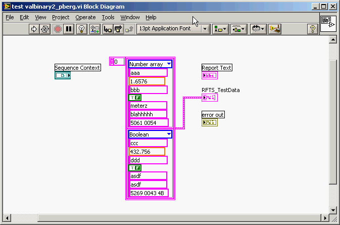
Attached file: valbinary2.vi containing the clusters of test output array.
Howdy Jean-Louis,
My apologies, I'm not quite your question. You're right that LabVIEW does not know that a string is a binary star strong; LabVIEW, chain stores in a format of Pascal, looks like all the strands in the same way. Because TestStand stores strings in the C type format, on the other hand, the null (0x00) characters can be confusing when interpreting strings in TestStand as you learned to understand. That is of course why TestStand offers the feature to interpret strings as binary strings.
As Sylvie refers to his post, to illustrate his point I created within TestSTand an array of the same type of data customized to store past out of your valbinary.vi of test data. Test patterns, I also edited the outputsome constant values to the cluster VI. (See the following screenshot). Note that the last string (named ValBinary) in the cluster contains a hexadecimal string with a null character that is inserted as the 3rd on-screen character (before the actual end of the string).
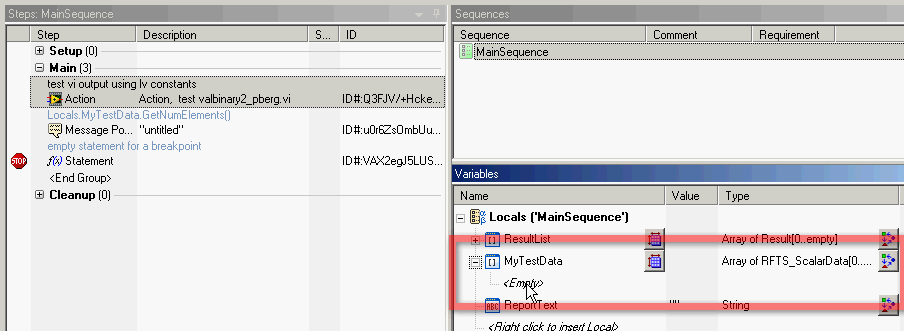
Here is a screenshot of the created sequence file that calls the VI and then displays the number of items in the table from the VI to the user. Note that the Locals.MyTestData table is empty before the execution of the sequence.
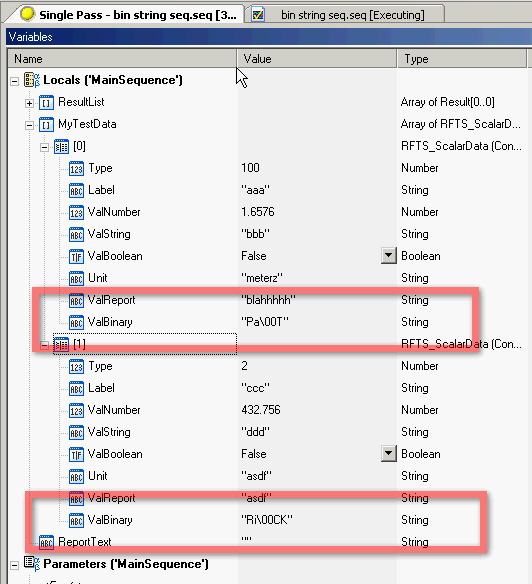
Finally, as the execution of the sequence, I opened the Variables pane to view the contents of the Locals.MyTestData table. Here, I have confirmed that the "binary" string of LV was successfully passed in and stored by TestStand.
Finally, the popup message in the second step of the sequence shows indeed a message indicating there were two elements in Locals.MyTestData.
This sequence has been able to run successfully even without manually specifying a size of Locals.MyTestData beforehand. TestStand dynamically allocated the necessary elements to store the results of test valbinary.vi.
-
Error 116 when a string of binary file reading
I try to use the 'writing on a binary' and "binary file reading" pair of VI to write a string to a binary file and read it again. The file is created successfully and a hex editor confirms that the file contains what is expected (a header + chain). However, when I try to read the string back once again, I received an error 116: "LabVIEW: Unflatten or stream of bytes read operation failed due to corrupted, unexpected or truncated data.» A quirk I found though, is that if I put "endianness" to "Big-Endian, network order", the error disappears when I use "native, welcome the order" (my original setting) or "little-endian" error occurs. Did I miss something in the documentation indicating that you can use big endian order when writing of strings, I do something wrong, or is this a bug in Labview? Because the program that it will be used for is to write large networks, in addition to channels, I would like to be able to stick to the 'native' setting for speed purposes and must not mix "endianness".
I have attached a VI of example that illustrates this problem.
I'm using Labview 8.5 on Windows XP SP2.
Thank you
Kevin
Hello
Please contact National Instruments! I checked the behavior that you have met and agree that it is a bug, it has been reported to R & D (CAR # 130314) for further investigation. As you have already understood possible workaround is to use the Big-Endian parameter. Also, I am enclosing another example that converts the string to a binary array before writing to the file, and then converts to a string according to the playback of the file. Please let me know if you have any questions after looking at this example though and I'll be happy to help you! Thank you very much for the comments!
-
Hello!!
I'm trying to store a waveform in a binary file. I use a labview 'write in the binary file' example as a guide. My waveform is a waveform that simulated the LabVIEW express menu "waveform simulation." Well, if I put a graphical indicator, I can see the waveform. But when I draw a binary file, a very bad image in the form of wave. Please, see the attachment. I use the theorem of Nyquist, who say that the sampling rate needs to be 4 times the frequency.
Please, if anyone knows, post it.
Thank you


Your problem is related to different endian format. Who will tell how the order of byte in the number are organized. To do this. In the toolbar, select Help and activate context-sensitive help. Hover your mouse over the "binary" function, and then select help in the Help window. Search for BOM
-
Hello world
I read so many lines and topics related to this BinaryRead I wonder how could I not make it work properly.
Shrtly I have a LXI instrument I used via TCPIP interface. The LXI instrument is called hollow driver an IVI - COM who use NI-VISA COM.
SCPI sending back answers without problem. The problem start when I need to read a block of IEEE of the VXI instrument. My driver is based on VISA-COM library and implemented a few interfaces formatted as IFormattedIO488, IMessage, but no ISerial that I don't need to use the interface series. The binary response from the instrument is: #41200ABCDABCDXXXXXXXXXX0AXXXXXXXXX which is made of 1200 bytes representing 300 float numbers.
To avoid getting the Stop 0x0A character which is part of the binary data stream, I turn off the character of endpoint using the IMessage interface and by setting TerminationCharacterEnabled = FALSE.
When I read the bit stream of the ReadIEEEBlock is always stop playback at character 0x0A anything.
I read al of the places in this forum that read binary stream properly by any instrument requires two parameters not only one that I have just mentioned.
The first, I'm able to control is on EnableTerminationCharacter to FALSE.
The NDDN is the VI_ATTR_ASRL_END_IN attribute that could be put in a pit ISerial interface only and I couldn't access this interface of my IVI - COM driver.
As we do not expect to use the interface series with our instruments of TCP/IP what other options I have to allow reading full of the binary stream of bytes, even when a 0x0A is inside.
Our IVI - COM drivers are written in C++ and use NI-VISA version is 4.4.1.
Last resort I tried to change the character of endpoints via interface IMessage for TerminationCharacter = 0 x 00 (NULL), but the ReadIEEEBlock always stops the character 0x0A?
Binary reading is performed inside the IVI - COM driver and if successful the full range of float data points is passed a potential customer request inside a SAFEARRAY * pData object passed as parameter to a public service of the IVI - COM. The problem is that I couldn't read to pass beyond hollow character 0x0A VISACOM interface.
Thank you
Sorin
Hi yytseng
Yes, I can confirm that the bug is from VXI-11 implementation on instrument LXI himself. Until binary reading all of the previous answers have been terminated by LF (0x0A) character who has the character to end on the device_write function. The VXI-11 specifications are very bad when talking about terminator on device_write then talk to the END indicator on device_read which is not necessarily the same for device_write and device_read. I talked to the guys implementing LXI instruments VXI-11 module and the two agreed to a lack of clarity about the nature of writing and reading processed stop. Ultimately our instrument for reading binary is only the form #41200ABCDABCDXXXXXX format the only character of termination to set TermCharEnabled = TRUE and TermChar = 0x0A, who could be the interface IMessage hollow of the VISACOM interface.
If the problem was not within the VISACOM, but inside the LXI, VXI instrument - 11 which has send the response of VISA as soon as detected a 0x0A byte value in the bit stream. Now after the BinaryRead change pass beyond 0x0A character but I find myself struggling to read in a ReadIEEEBlock appeal huge amount of float up to 100,000 points data, equivalent to 400,000 bytes for buffers used between instruments LXI and VISA are very small about 1 KB only.
In any case the solution to my original question was the poor implementation of the VXI-11 instrument on the treatment of device_read termination characters
Thanks for your help
Sorin
-
convert the binary signal in numbers
Hi all
I searched and I can't find a simular solution to this issue, so I hope that somone can help me. It's probably pretty simple, but as I'm new to Labview, it takes time to get used to the programming language.
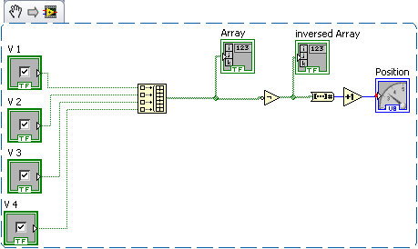
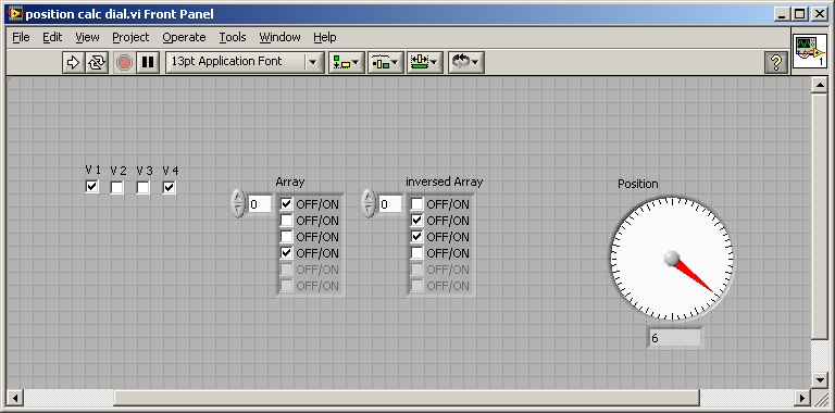
I have a rotary switch with 16 positions made-to-measure. The valve has 5 inductive sensors, mounted on a turntable of the holes drilled for the positions.
With 4 sensors, there is a binary code, created for 16 positions.
v1 v2 v3 v4
1 1 1 1 pos 1
0 1 1 1 pos 2
1 0 1 1 pos 3
0 0 1 1 4 pos
1 1 0 1 pos 5
0 1 0 1 6 pos
1 0 0 1 7 pos
0 0 0 1 8 pos
and so on...
The fifth sensor is (1) when the water is rotating and (0) when the valve is in the position.
What I build with LV is a surveillance system for this valve.
How can I use the 5 digital inputs (simulated with Boolean switch) in labview and convert a digital indicator for the position of the valve?
I hope someone can guide me in the right direction with this problem.
Thank you.
Here's a solution
put them together in a table, reverse, convert it to a number, add 1, DONE
the red dot could be avoided, but now your homework

-
How to ensure that the binary file is stored in the location specified for my DLL files?
I'm new to computers and has a Dell Inspiron 1545 laptop with a program in Windows Vista Home Premium on a 64-bit platform. I have a thread in my sidebar gadget new MSNBC and the dates for the stories are frozen in December of last year and does not update the current stories. I had no problem with this before and I haven't added or deleted programs because of this problem to the best of my knowledge. I got advice here on the checking of dll files and 4 of them come back with saying error messages and see that the binary is stored at the specified location for debug files. I searched for information help with this and I found a few tips that not saved and re-entered the files, I tried and different versions of the idea, at first it made no difference and then I redid it and it screwed up my weather gadgets so I redid it and they worked very well. I then tried on the DLLs for the MSNBC gadget, but it doesn't seem to change anything, although the gadget to power for the Dow Jones News feed is now screwed up. Is there a site I can go to what can explain the route of binary/specified path or debug file. Save/re seems to be the right path, it affects obviously the gadgets but not as I want, any help in this direction would be appreciated at. Meanwhile I'll go back and try again.
Hi dumdeedumdum
What are the files dll are facing problems with?You can perform a SFC scan and check if the problem is resolved.
To Perform a Scan SFC -
a. click Start, click programs, on Accessoriesprincipally made, right click guestand then click run as administrator. If you are prompted for an administrator password or a confirmation, type the password, or click on Allow.
b. type the following command and press ENTER:
sfc/scannow
A message appears indicating that "the system scan will start. Be patient because the scan can take some time.
c. If all files require a SFC replace will replace them. You may be asked to insert your Win7 DVD for this process to continue.
d. If everything is correct you should, after the scan, see the following message "resource protection Windows not found any breach of integrity".
e. once the scan is finished, close the command prompt window, restart the computer and check.Check the link below for further guidance on scan SFC - mentioned
http://support.Microsoft.com/kb/929833I hope this helps.
-
Lost data of binary message J2ME
I have a MIDlet that works on other devices. To do this, an HTTP POST of binary data on my server. It follows the Connector.open (normal), HttpConnection.setRequestMethod (), HttpConnection.setRequestProperty (), HttpConnection.openDataOutputStream (), DataOutputStream.write (), DataOutputStream.flush (), HttpConnection.getResponseCode (sequence). When you run the app on the JDE/MDS, publication data do not appear on the server, even if I see that writing to output stream of the HTTP connection is executed; the newspaper of MDS, it says that the connection to the HTTP request entity section is empty:
<2009-03-17 16:59:51.874="" pdt="">:[102]:
: : I tried both with the type of content set to "application/octet-stream" and jumped with no difference. Are there restrictions on the type of content in a post from BlackBerry? Is there something special about to do a HTTP POST of binary content on BlackBerry? The content-length header would be necessary? My apologies if I missed some already documented information. I saw the other posts on an empty HTTP POST content, but none seems to match my case. I was able to get HTTP GET, this is the display of binary data, with that I have problems.
I use JDE 4.0.2 to target all MIDP 2.0 devices.
I found what triggers this behavior in the simulators. I had a bug in my code that caused it unwittingly (although permitted by the standard RFC 2616) write a HTTP header with an empty string for a value. I would say only that it is triggered a bug in the device Simulator that then swallowed this header (which explains why the header was not the newspaper of MDS) and has failed on the output with the HTTP POST data stream.
Looks like an abstraction of the code triggering the bug:
// ...String locale = functionThatReturnsEmptyString();// ...HttpConnection hc = (HttpConnection)Connector.open( "http://foo.com/bar", Connector.READ_WRITE, true );hc.setRequestMethod( HttpConnection.POST );hc.setRequestProperty( "User-Agent", "BlackBerry7290" );// Content-Language header value is empty string!// and apparently never makes it from device simulator to// MDS simulatorhc.setRequestProperty( "Content-Language", locale ); // ...byte[] ba = dataToPostViaHttp(); // my binary POST dataDataOutputStream dos = hc.openDataOutputStream();dos.write( ba, 0, ba.length );// data not truly flushed due to HTTP header with empty string for valuedos.flush(); int rc = hc.getResponseCode();DataInputStream dis = hc.openDataInputStream();// ...
RFC 2616 at http://www.ietf.org/rfc/rfc2616.txt is clear enough that an empty value for a HTTP header is legal in HTTP:
2 Notational Conventions and Generic Grammar 2.1 Augmented BNF All of the mechanisms specified in this document are described in both prose and an augmented Backus-Naur Form (BNF) similar to that used by RFC 822 [9]. Implementors will need to be familiar with the notation in order to understand this specification. The augmented BNF includes the following constructs: ... *rule The character "*" preceding an element indicates repetition. The full form is "
* element" indicating at least and at most occurrences of element. Default values are 0 and infinity so that "*(element)" allows any number, including zero; "1*element" requires at least one; and "1*2element" allows one or two. [rule] Square brackets enclose optional elements; "[foo bar]" is equivalent to "*1(foo bar)". ... 4 HTTP Message 4.1 Message Types HTTP messages consist of requests from client to server and responses from server to client. HTTP-message = Request | Response ; HTTP/1.1 messages ... generic-message = start-line *(message-header CRLF) CRLF [ message-body ] start-line = Request-Line | Status-Line... 4.2 Message Headers HTTP header fields, which include general-header (section 4.5), request-header (section 5.3), response-header (section 6.2), and entity-header (section 7.1) fields, follow the same generic format as that given in Section 3.1 of RFC 822 [9]. Each header field consists of a name followed by a colon (":") and the field value. ... message-header = field-name ":" [ field-value ] field-name = token field-value = *( field-content | LWS ) field-content = [Note that the 'value' field is explicitly as an option with the hooks in the production of "message header" and that the "*" notation is used in the production of "value field", indicating that it may be explicitly zero cases of 'field-content'.]
So I have this part of my code working now, but I would say that this indicates a bug in the software of simulation and may be combined in the combined software as well (haven't tried).
-
Disable the Caps/Num Lock Indicator
So I have this REALLY annoying indicator and I cannot figure out how to turn off. He appeared just today after my keyboard locked out of the blue. I have not installed new drivers in more than a week or 2. It is also on a desktop computer assembled by hand with no preinstalled software.
I don't know what is. I use a Logitech G19 keyboard with 8.50 drivers LGS and I see no indicator in its parameters (point set is not installed or is - it a process). The control panel is out of no help as its parameters of immobilized the Num Key for 5 seconds does not work and also the neutralization of him does not.
Hi, elegant,
To the left of the keyboard above the SHIFT key, press Caps Lock. This should stop the message.
Search troubleshooting links here
- Press Start > Control Panel > access > easy access Center > make the keyboard easier to use
- Make sure turn on toggle keys is not checked
Disable the popup lock and num caps
Start, type Regedit
Navigate to the following key
HKEY_LOCAL_MACHINE\SYSTEM\CurrentControlSet\Control
Double-click on "Keyboard" to open the folder.
Open the "Edit" menu and choose "New" then "binary value".
A new file will appear to the right of your screen with the name of the file highlighted.
Type 'Scancode Map' for the new file name.
Double-click to open type in "00000000 00000000 0200000000 003A 00 00000000" in the value data box.
Press the OK"" button.
Close the editor of 'register' by selecting 'Quit' in the menu 'file '.
Restart your computer so that the change takes effect and enjoy life without the SHIFT key.
-ehow-
Maybe you are looking for
-
8200e graphic sff updated card?
Hello Can someone tell me how big a graphics card can I put in a HP 8200e SFF? Is the system locked to standard som HP graphics cards or can I put with any card I want? Thanks in advance :-) Concerning / Bass
-
BIOS update failed on the Satellite X 200-213
HelloI have a Satellite X 200-213 with vista. My main problem is that I was quietly updated the bios when suddenly cut off electricity! You can imagine my head... So, as soon as now I'm crying because my pc reboots at all! Black screen. My question:
-
When I try to attach a PDF to an email, it always shows the whole document and not an icon.
When I try to attach a file to an email, it shows the entire document. Is this a setting problem? I've tried everything.
-
What memory can I use in Satellite M40-184?
This memory module to add for laptop Toshiba Satellite M40-184?
-
I'm upgrading to a new Mac Book Pro, my 'old' goes to a friend!
Hi all, I'm going to upgrade to a new Slimline Mac Book Pro, my 3 year old outgoing Mac Book Pro goes to a good friend of mine, I tried for years to make him give up Windows, finally, he took the bait. So I ask, how is it best to prepare my old MBP b