Binary output to the digital output as 1111 1111 1111 pin
Hello
I use DAQ 6009 and I need output such as 1111 1111 1111, at the digital output (12) of data acquisition. Please give an idea or a vi to do
Thanks in advance...
Hi DK,.
Look through the viewfinder of the example for example appropriate screws...
In general: open/create one task DAQmx, select all lines, exit TRUE for all channels...
Tags: NI Software
Similar Questions
-
How the names of variables and units used in the binary output file
My colleague will give me LabView generated from the binary files (*.dat). There are more than 60 variables (columns) in the binary output file. I need to know the names of variables and units, which I think he has already configured in LabView. Is there a way for him to produce a file that contains the name of the variable and unity, so that I'll know what contains the binary file? It can create an equivalent ASCII file with a header indicating the name of the variable, but it does not list the units of each variable.
As you can tell I'm not a user of LabView, so I apologize if this question makes no sense.
Hi KE,.
an ASCII (probably the csv format) file is just text - and contains all data (intentially) written to. There is no special function to include units or whatever!
Your colleague must save the information it records the names and values in the same way...
(When writing to text files, it could use WriteTextFile, FormatIntoFile, WriteToSpreadsheetFile, WriteBinaryFile even could serve...)
-
analog sync of input with the onset of the digital output
I'm trying out an analog signal to a file with a specified frequency samples. I also need a digital output to trigger a measurement at a frequency specified on a separate system. The frequency is controlled by the loop exits and timed when the iteration number divided by the period is exactly a whole number.
Both outputs work. The problem is that they are not synchronized. The analog output amounts to about 0.5 ms faster than the digital signal. (I checked with an oscilloscope) They both start in the 1 ms each loop runs for, but I really need them to start at the same instant. What can I do to synchronize? Also, if I'm going in the wrong direction complete, please indicate.
I use a card PCI-6723, which I think someone at some point, said not having a material sample clock. That's why I try to use a timed software loop.
Hi NEA.
You must use the 6723's built-in calendar to accomplish what you want. As the digital output subsystem is only clocked by the software, an appropriate solution should be to use one of the counters to the pulse output.
The attached code should show how. You can use the counter to output a pulse all samples of the AO N task. Material requires the initial delay to have a minimum of 2 ticks, so the meter will be behind the task of the AO by 2 samples in this case. There are different ways to work around this problem if you need (for example write two samples of 0 first).
Best regards
-
vary the value of output of the digital HIGH output voltage.
Hello
Is it possible to vary the values of the NOR-DAQ HIGH output voltage. If Yes please tell me how to do the same. I want to reduce tension before moving out of my camera, digital signal as my rating of device is only 3 volts for the digital HIGH.
Kind regards
Pradeep.
The digital output voltages cannot be changed on your USB-6259 (that you mentioned that you use in a different thread). Please see the specifications for more information on the digital logic levels used on your Board.
Best regards
-
Acquire the values only when the digital output is high.
Hello
I work with test of transistor, whose door is controlled by the digital release of USB6289, related to BNC2120.
Test plan:
Door 1.transistor is enabled for 5seconds, with P0.0 for example
2. then, everything remains off for 1secondes.
3.p0.1 is used as digital output to activate the circuit passing him curent through in the opposite direction, P0.1 goes high for 3 seconds, PS: Gate is off.
4. the same cycle repeats again.
My question is to store values to the output of the transistor when P0.0 and P0.1 goes high, and these values should not change until my digital outputs respective again go high.
I can access transistor by continiously read out my power supply values.
and in the State off I want to read AI0 because at that time, my power supply is off, so that I can activate the circuit to pass the current in the opposite direction.
Again, my question is to gain the output through power value when P0.0 is high and store them until the transistor turns on.
and even for P0.1, acquire the value of output through AI0, when P0.1 is high and store it until it goes high again.
Hopefully, I'm able to explain my problem clearly.
Please help me.
Concerning
Anurag
Think about what States (object:statemachine and determine when to use sequence Structures) do you want from t0... t(n-1), IF DAQmx generates outputs and/or inputs are absorbed and what needs to happen (event timed out), before move you on to the next 'State '.
type def 'enum' with your different States:
- initialize
- wait (the user initializes times (sec) set for States, or whatever and presses button 'Start')
- T0 (generate DigOutputs, store acquired data AnalogOutput (string output number) the register shift, before moving to the next State > user 'set time' must elapse (Note: the wait function allows you to control the rate of execution of loop and allow the CPU to respond to external events and system tasks and avoid using wait functions at the same time an operation of software...))
- ...
- t(n-1) if ' end (made requirement) "> goto 'stop', ' another (not requirement not)" > goto regardless of 'State '.
- stop
- write a text file of data (string).
-
What is the current max on the digital output of a Terminal BNC - 2110
Im a using a card of data acquisition of 6221 with a block of connection BNC-2110 connected to it. For the e/s digital terminal block provides an additional 5V input. Unfortunately I don't seem to find any information as to know if this provides additional current to the TTL signal or no training. Is there an internal pilot in the terminal block, or - if I need to connect external relays to the digital output - always connect a current driver in between?
Thank you
Wolfgang
You can replay the 6221 and BN_2110 manual. The + 5V pins are outputs of the DAQ card - they are not entries.
Yes, you will need external circuits if the external relays require more current than can provide the DAQ card.
-
How to configure the digital output of the pci terjeta 6023E in LabVIEW 8.5?
Hi, I have a card PCI-6023E and LabVIEW 8.5 and I need is to configure the digital output on the card, but did not.
My idea is to get a port of digital data on the map and control by a pwm small dc motor.
I wonder what are the modules with which you can do.Hi skudero,
Probably the web page tracking and the attached example will work.
PWM in software timing using a digital output line
Concerning
Charley - NIB - SR 1368189
-
an alarm can be set to control an external device using the digital output?
My employer is considering buying a 6210 DAQ and SignalExpress (we currently use a branded DATAQ device).
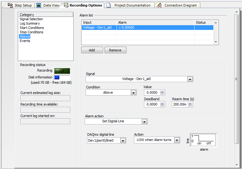
Looks like I can use the alarm function SignalExpress to define a logic high or low line, controlling a SSR to stop a pump (a non-critical application).
Can I use SignalExpress in this way?
I know LabView can do, but there is no way that the company appears for him.
Thank you.
Hi Jack, this is Paul with Applications Engineering at National Instruments.
SignalExpress supports the functionality you want.
«Once you have configured your signal to acquire you can go to "Save Options" > "Alarms" and then set the alarm conditions, and then choose your Action to alarm as «Defining the digital line»»
I've attached a screenshot of the example of this configuration.
Note here that I put it down when the alarm turned on. You there are other options, including a rocker.
Let us know if you have any other questions!
Paul
-
is that any limits the current entry for the digital I/o?
Hi all
I wonder if there is no limit on the input to the digital I/o port. I have a device about 0.2 volt voltage outputing and the manual says the maximum sink current is 25mA. I connect this signal to a DI entry in my 6711 map. I wonder if the current is too large for the entrance of DI or the PFI?
As we have already mentioned, there is no current flowing on the device in low level mode.
The current specifications mentioned see the maximum current that can be managed by the device in low level mode.
I hope not to confuse you more than necessary. On a row of data to the TTL level, nothing flowing from the device to the main circuit in level mode high current. In low mode, there is flowing in the main circuit in the current device. This current is inherently limited by the circuit.
So, if you have a file specification of 25mA max. of the peripheral device in low level mode, it will never sink too much power from the main circuit. You can connect two devices without any risk. The maximum current is just specified in case you manage more current with the device, a led or a relay for example. In this case, the charge current must be limited, so that you do not damage the device. But - as mentioned - this is NOT the case in your application.
-
Problem with the digital data to write VISA function
I have a GE's PowerPC that is running on the VxWorks operating system. I have a tornado application where I run my C code to generate a file .o & .out, then I empty image .o files & .out for PowerPC via FTP, now I need to communicate with PowerPC of LabVIEW (via serial communication using VISA vi) using the VxWorks controls. When I enter orders VxWorks in LabVIEW
That is to say for Eg: 1 > ls --> the contents of a directory list IE .o & .out files. The problem I'm facing here is, when I run the vi, I am able to read the file in the box to read the string but keep files on speeding up juice,
2 > ld <> --> load a module object in memory. I face the same problem here.
3 > then I need to type the name of funtion main c program, after which I can give input to the program.
4 > I need to enter numeric data as inputs to my program. but the write VISA function accepts the only input string and read VISA function gives only out of string... I want to give digital entries and read the digital output. Any help would be appreciated.
Hi Luke,.
You can try with this reliable hyperterminal VI.
-
simultaneous monitoring of the digital input lines when executing digital writing tasks
I'm writing a multithreaded application in C on Windows 7, using the 9.6 DAQmx API and device USB-6509. This requires that we constantly monitor several lines on the 6509 for entry, digital using the change of the device detection feature. You must also write the digital output without having to stop monitoring the input rows. It is very important that the input rows be monitored continuously for the duration of the project.
In the DAQmx manual reading, it seems that it is impossible to make a digital reading as well as a digital writing occurs, even if these tasks are performed in different threads. (The same I understand, that it is impossible to have several tasks of digital entry running simultaneously.)
It seems that it would be possible to launch the task for reading (configured with the change detection), to pause playback, start the writing task, pause the task of writing, and then re - start the task of reading. But - and this is the important part - for the duration of the writing task is running, is it possible to configure it to the task of reading will always monitor the lines, even if it's just stores the data in the buffer for these periods? The key is that the data will be lost.
Thank you
Danielle
Each channel is independent. If you can get the input data that you export a value. You need not make a break each task. The two tasks are parallel.
-
Reading binary Dump using the DMA (Direct Memory Access)
Hi all
We are trying to measure short-term frequency using the SR620 (frequency meter) via a GPIB-USB connector. We are trying to understand how to work the controls GPIB, and it seems that you normally send a query and then ask him to read what says the instrument. However, as we try to make a measure of frequency stability in the short term, we use the binary Dump command (BDMP - explained in the manual, link below). To read this data, you do not use the standard playback function, you use this process called base (DMA, Direct Memory Access). The maual speaks DMA and the example code in the maual seems to use DMA to read the data that results.
We have been able to trigger the display of "binary output" on the instrument using LabVIEW and interactive control via the NOT-MAX. The question now is: How do we implement DMA by using LabVIEW? More specifically, how we implement DMA reading of the SR620. It doesn't seem to be anything close to it in the code of LabVEIW included. There are examples that use the DMA with IVIs, but we had difficulties to change to work with the SR620 code.
Useful links:
Manual for SR620: http://www.thinksrs.com/downloads/PDFs/Manuals/SR620m.pdf
Possible example DMA? : https://decibel.ni.com/content/docs/DOC-9893
DMA explination: http://zone.ni.com/reference/en-XX/help/371599J-01/lvfpgaconcepts/fpga_dma_how_it_works/
How to make DMA: http://www.ni.com/white-paper/4534/en/
Note: When we did not step 1 passed because we have problems adding a new target of the FPBA, because there is "
". Yes, in ' 89, you probably use a DMA to store the data fast enough. In 25 years, things have become much faster. What I did to somehting similar is to save the data to a file as it is being read. If you want more performance, use a producer/consumer.

-
PCI-MIO-16-1 shows the digital inputs 1-7 on, without same cable connected
Max, my PCI-MIO-16-1 shows the digital inputs 1-7 as having entries of tension without same cable connected to the Board. No amount of spin with her (to the MAX) seems so he can act correctly in input or output mode. It's true, there are voltages on these pins. If I connect my cable (to a TBX-68 block), I see that it has on $line0 (on port0) 0v, 5v on line7 and 2, 5V on the rest. Trying to put these lines to something else in MAX seems to do nothing. (I also can't control the OD, either.)
This card has tried to get a couple of have Weiwei at high speed. Now that I'm branching out, I found a strange behaviour. Of course, I tried to restart and turn off the computer and turn it back on. Automatic test MAX Returns instantly with a message "transmitted", that gives me hope, even if I don't trust the speed at which it seems to perform the check.
I'm a complete noob at this stuff. Is there something obvious that I might be dominant? Is there a way I can test more deeply that the card works as it should?
The open connections to the TTL inputs are usually detected as logic 1. You are not testing properly. Connect an entry to two gnd or + 5V. Don't let them ever floating.
-
I have vista SP2, I connected to generic stereo speakers using the green light at the back of the computer. Vista does not recognize the speakers. The speaker symbol at the bottom right shows "digital (HDMI) 2 high definition output audio device." It shows active. I had this problem before, and VISTA should pick up 'speakers' something to that effect. I have no sound until it captures "speakers". I can't get VISTA to recognize this. It keeps starting with the digital audio device. Don't know what to do, checked all the forums. It should just pick up these simple generic markets good speakers. Before SP2, I lose sound when VISTA is in standby mode. He would then turn off the stereo speaker and replace the digital output device driver... However since SP2 I can't get VISTA to recognize that I have just connected speakers and not a digital output device.
Yes, when I uninstalled the driver, THEN shut down the computer and then restarted, he picked up the device high definition audio "speakers" good pilot is NOT the
"digital (HDMI) 2 high definition audio output device that he used to pick up."
I now have sound!
I hope that it stores the right driver now as in the past, when VISTA went into sleep mode, it will disable the speakers, and you have to restart every time.
Thanks for your help.
You can add instructions to boumediene, the fact that you must RESTART your computer to search for new drivers, once you uninstall.
-
Connect the digital field with Drop Down
I have a numeric field for the zip code and a drop for the city.
I want that when I write the postal code in the numeric field to automatically display the city drop down list.
And even when I chose to drop down the list then show in the digital field (postcode)
I have all that in Excel.
Thank you
Use dynamic properties.
Start by importing the xml from your spreadsheet (you're on your own with who) excel. Assuming that each line is a city and a postal code, your xml code will look like this:
SomeCity 12345 .
.
.
(1) in the designer, go to file > new connection of data...
(2) select the sample XML data and the file in Excel.
(3) make good properties sure dynamics are enabled, tools > Options > Data Binding > show of dynamic properties.
(4) select your fall down and open the field in the object Palette tab.
(5) you will notice that the list items is green and underlined. Select it.
(6) for items, select the line
(7) for the text of the item, select the city
(8) for the value of the item, select the zip code
You now have your menu dropdown bound to the data in your Excel worksheet.
Now, just a bit of coding (brace yourself), in the digital realm for your zip code, in the case of output put:
theDropDown.rawValue = this.rawValue;
and to theDropDown:
thePostalCode.rawValue = this.rawValue;
Now all you have to do is import xml into your form to perform.
Kyle
Maybe you are looking for
-
RoboForm does not work on version 4.o1
I updated Firefox to version 4 and RoboForm does not work anymore. When filling out the forms is clicked nothing happens. When I open the connection menu and click a site to connect nothing happens. It still works fine using IE so I doubt that there
-
I have WVC54GCA camera. I've set up motion detection, but the e-mail test fails every time. I have three e-mail addresses. I have send to two and use them as sender. I tried all three as the sender, but no combination works. Any advice?
-
How can I change the product key Windows 7 starter edition
Hi all I tried to change the product key on my netbook, because I had to replace the hard drive and I used my recovery disks of the brothers that he has the same exact model. However when I had done restoring the product key is also the same so I wan
-
BEX errors during the installation of the software/program updates
I have recently upgraded to an SSD and a new drive hard on my PC and thought, everything was going well until I started to reinstall and update my old programs, where I keep coming across mistakes BEX I can't work around with my computer DEP settings
-
Unable to connect laptop to a wireless printer
Hello: We have a laptop HP with Windows 7 Home Premium 64-bit. and a HP all-in-One Photosmart Premium C309g printer/copier/scanner. It was all together upwards and work wireless very well for a few years. Our wireless router went wrong. We replaced o