Block diagram of... block diagram
Hi, I need your help. IM the wrong person for this post, but I have to do, so I depend on your help. I need to explain how LabView (pasted below) program works, but I don't understand it myself  I would like to ask if someone can create a simplified block diagram of the pattern-block LV I paste it here. I appreciate all the help and please take considaration I am short on time
https://DL.dropbox.com/s/yd10z7yorxvbzux/LVdiagram.jpg
It is a counter. Meter of photons to be exact.
Hi, Rodolphe,.
I will try to explain briefly what is this application:
Following materials may help you understand the underlying concepts:
http://www.NI.com/PDF/manuals/371022k.PDF
It is the manual of series M - chapters 6.7 and 8 explains how digital lines, meter and what is a PFI.
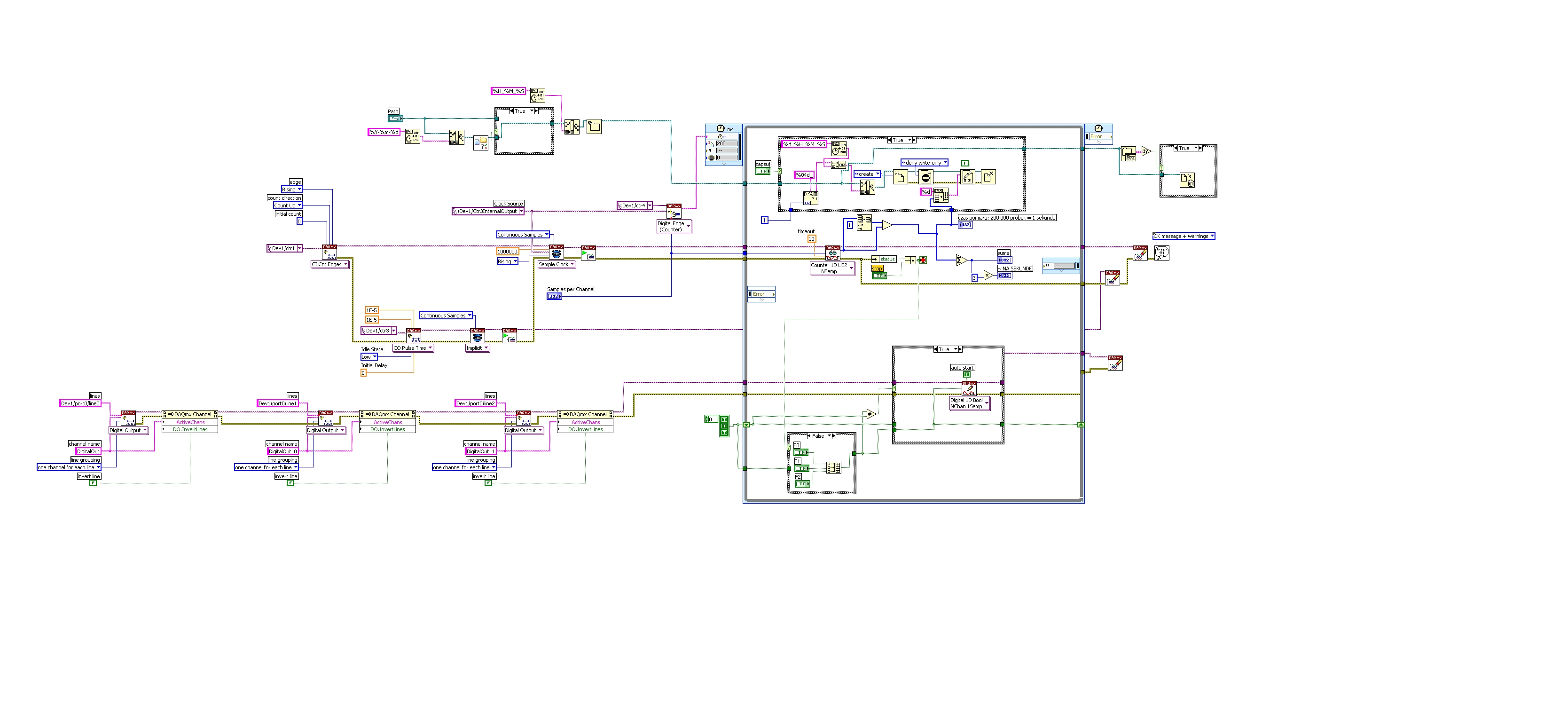
When you open the block diagram of your application, you can see several branches ranging from left to write.
The first one on the top is to create a path to a file. This path will be used to write data to a binary file. The data represent the number of impulses which can be counted as edges rising a signal connected to the meter to 1. This information CA be read if you follow the logic on the second branch from left to right, where the first VI is CI INT edges (edges of counter), and it will count up, on a rising edge of the signal connected to CTR1.
Later, there is another task created for counter 3, that generates impulses. The pulse seems to have 10uS length and 50% duty cycle. The signal generated by this counter is used as sample clock for measure and 1 meter. In addition, the same meter signal 3 will be used by 4 meter from the digital dashboard and create a clock which will clock the timed loop. Basically, the frequency of the timed loop is given by the task on 4 meter which counts pulses generated with meter 3.
The 3rd branch from left to right, creates three tasks on three outputs digital: Line 0, 1 and 2 where it is controlled by three buttons F0, F1 and F2. Basically, your timed loop will be a specific iteration, and every iteration buttons will be read and will be updated to the specified digital output above.
Whenver there is a mistake or the button is pressed, your application stops and closes the binary file and dealocate resources used.
I invite you to also look in the above manual.
Best regards
Ion R.
Tags: NI Software
Similar Questions
-
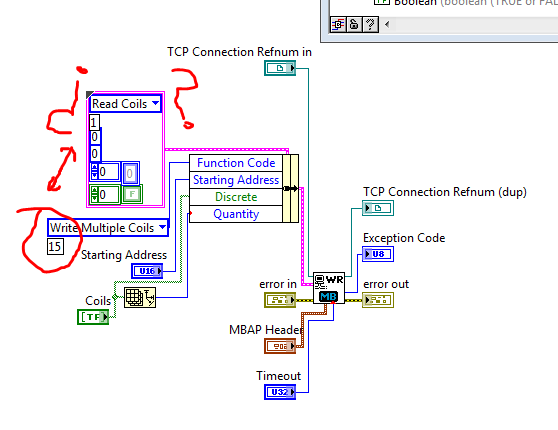
What this block diagram?
Match a VI Modbus Library. But I have because if the block is configured to write multiple coils in the coils because reading is set to 1?
All this work?
Sorry if the question is a beginner.
In this block diagram, 'Coils Read' and 'Write multiple coils' are enumerated values (or possibly ringtones of appeal, which is not serious for the purpose of this explanation). Enumerations assign names to numbers, to make them easier to read. The coils Read command is set to 1, the command to write multiple coils has a value of 15. You don't need to worry about this number, however, because the enumeration takes care of it for you.
The constant cluster containing coils of reading is there just to provide the correct data type (a cluster with the right items). Almost all the elements of the latter shall be replaced by the values of wired in the Bundle to node Name. For example, the value of reading coils is there as a placeholder for any function Code. the actual Code of the function is defined by plugging write multiple coils in Bundle by name.
-
SCB-68 Terminal Block quick reference label does not match PXI-7831R pinout diagram
I want to connect 3 analog inputs for the of IO reconfigurable NI PXI-7831R Module, use the connection series SCB-68 M block. I noticed a gap between the analog inputs, shown on the terminal block of the SCB-68 quick reference Label and the analog inputs captured in the pinout diagram 0 connector NI PXI-7831R. For example, the NI PXI-7831R connector 0 pinout diagram shows AI3 - and AIGND3 on the 29 and 30 pins, respectively. The label for quick reference of SCB-68 watch GND AI and AI 3-pin 29 and 30, respectively. There are at least six other cases where there is an incompatibility between the quick reference label and the pinout diagram. Has anyone else seen elsewhere?
Look at the label of SCB - 68 quick reference? M-series would be for the cards M Series DAQ devices where as the PXI-7831R is in the R series. You can see the difference here in this KB which has both the M series connector and connector M 7831R.
I hope this clears up things!
Greetings from Austin,
-
Clean using SubVIs block diagram
Hi guys and welcome to my first post!
I m a bit new to labview, so be a little patient, if I do not understand everything immediately
Im working on an existing program that is used to control an MCU on BabyLin on my front, although I have a visualization to see live changes to the system. The program works very well so far, but I m trying to clean up the block diagram. This should be done by subvis, right? I ve read a lot about the size of the block diagram should not increase my screen. Well, im at a length of about 3 x 2 screens (24 "!) after trying to use subvis and to shorten the distances between structures. The only things remaining are huge amounts of local variables and references (they existed already before I got to know the program), mainly for viewing. If I create a Subvi part containing the people of the country, it will change the references that does not make the program more readable (and small), and I guess I can't put a new Subvi on references + Subvi.
You have any ideas what to do? I hope that I forgot something, otherwise, do not hesitate to ask.
Kind regards
Leo
Bob_Schor wrote:
To get a handle on the structure of your high-level code, write down (as if you were telling your boss or tell your wife - who knows, they might be the same person!) that you are trying to do. Keep it pretty General. You specified a number of steps? So maybe the top level should be a State Machine, or a message in queue manager. Describe you something that works at a constant speed, generating data that you have to manage "on the fly"? Maybe it's a design of producer/consumer.
You have a lot of initialization? Put in a Subvi, bring the 20 son out in a bundle (it's "Boss-word" for a Cluster). Your main program must have a few loops, with values that persist (possibly changing) during the program running in Shift Registers near the top of the loop, with tables and Clusters used to keep related items "consolidated".
Not too bothered by the size of your routine - I recently downloaded a monster 50-monitor the Forums (I did not even try to understand), up to 6 monitors is nothing!
Let "encapsulate the function" and "hide details" to be your guide in the reflection on the creation of the screws.
Bob Schor
To develop on the analogy of Bob, each talking point can be a Subvi. In other words, code group associate subVIs. The advantage of this is that it is much easier to solve problems because all errors will be localized to a Subvi. Errors no longer Chase around the block diagram. I guess you can use your current VI as an example of what NOT to do on the block diagram.

-
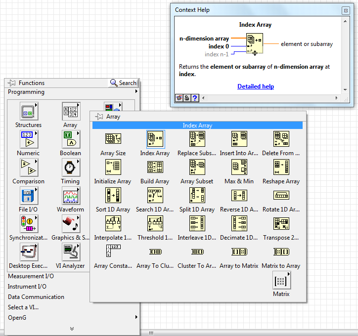
Index Array icons: Palette and divergence of block diagram
Hi all
Why are the Index Array icons discrepants?
There is a small difference between the two of them...
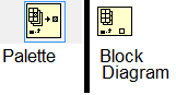
... That's how you see when you look at the table Palette...
... But this is how it appears when it is placed in the block diagram.
Compare yourself:
Is there a reason for this? I don't really know. I also looked for a thread about this, but I have found no.
Have you ever noticed this?
BTW, I'm using LabVIEW 2012 SP1.
Best regards

Hi João,.
so to summarize:
-l' icon changes when wiring to a 2D array entry rather than a 1 d of entry table
-l' icon changes too much wiring when a 2D array input and, in addition, all the wiring index entries
-l' also
showscontext help leaves how to index more than one element of an array-the range (maybe) shows an old version of the icon
There is more than a simple icon fixed to IndexArray function, but that only one version is displayed. You will notice this behavior for many more functions...
-
block diagram window becomes higher in win7 64-bit using LV2011 32-bit sp1
I have a strange problem and I wonder if anyone has ever seen this behavior. Often, when I go to the block diagram window, it will become the top window that is it is located at the top of all other windows including LabVIEW non-windows! I have to close the VI and really open to fix the problem. I see this on 3 machines, all the dell of m6600 laptops so I think it's maybe a graphics driver issue. Any ideas?
Thank you
Michael.Tori,
I confirm that this problem can be solved by removing the Dell Premier color utility that installs with the driver dell put on hardware compatible color first. The question of the window occurs when LabVIEW works so there is some kind of conflict. Anyway, problem solved for me. -
Reduce clutter in the control on my block diagram reference...
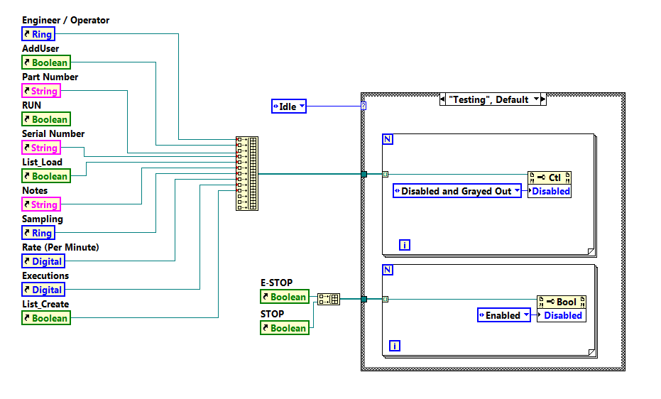
Is it possible to reduce the amount of clutter on my block diagram when needing to enable and disable controls so that the tests are running? I know that I can place the instruction box in a Subvi, but I'm looking for the best method recommended to reduce clutter when listing references. Using LabVIEW 2015.
Here is a small example of what I speak, there will be only for references to be added as the devlops of VI.
Thank you
Kellen
rkmadse wrote:
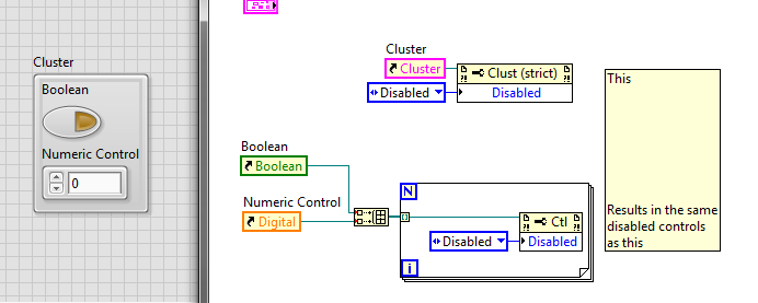
When you say I can clustor FP, say things that I did, and I have a group of controls such as those below in a clustor. I still have to generate reference constants, which are then placed in clustors. If I want to disable I would have then to consolidate each reference in the clustor, then ungroup and disable each control individually. I bet I'm really missing the point here and I'd love more explanation.
Thank you
Kellen
My main problem is not being able to place real dangerous in a Clustor.
You think about transportation, when I talk about the horse. Your façade elements can be in a cluster, and then you can use the reference to the pole to disable all. See:
You will get a façade looking slightly different between the two options if you use disabled and Grayed out because when you grey on the whole cluster, the gray edges. When you gray unique items in the cluster, the cluster edges remain normal.
-
In LabVIEW 2010, I have a Def Type control i.e. a Cluster with several other controls within the Cluster. Apparently, the references to the controls in the block diagram are based on the order that the controls have been added to the Type definition command. The side effect of this is that if a control is removed from the command of Type definition, many of the done Variable reference in the block diagram or now either broken, or worse still, refer to wrong control in the Type definition. These problems are quite difficult to find and fix.
Comment: If you create a control of Type definition and make a Cluster. Now add any controls to the Cluster in an order, let's say A, B, C, D. Their types does not matter. Now use the Type definition in one or more controls on the front panel. In the block mark references to controls inside the Type Def would control on FP. Now return to the Type definition and remove the command B of the definition of Type. Now, lots of errors appear. Broken links. But worse still, you see old references to B that now refer to C and old references to C are now referring to the old references to D and D are removed altogether, etc.. This side effect is much more errors, broken links and misreferences than expected otherwise.
How add and remove controls anywhere in a Cluster in a Type definition, at will, without creating a whole bunch of errors in program, broken links and misreferences for controls in the Type definition that have not changed?
-
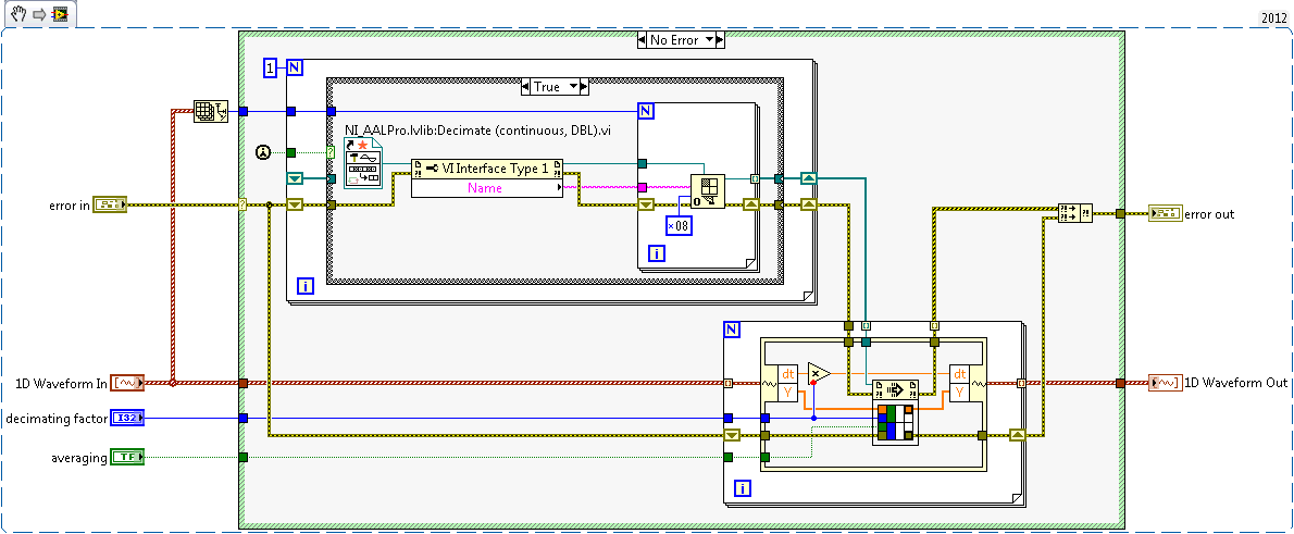
I have a double 2D chart I want to decimate continuously using the ".vi (continuous) Decimate" located in the range of Signal Processing. This VI is set on reentrant preallouee clone because it uses a FGV to save the State of the call to. What I could do, but do not want to, is having a huge index table and wire 20 + 1 table of DBL to 20 + unique VI instances decimate to ensure that each have their own data space and no 'cross-talk' doesn't happen, then 'picture of generation' all back after the fact.
I'm almost certain, there is a much cleaner way to do it with only one instance of unique block diagram of the VI decimate using techniques of the call by reference. I found my way to this link: Preallocated-Reentrant-VI-within-Parallelized-For-Loop that talks about something similar. After reading pages of four and the detailed help about the function 'Open VI référence' my head is spinning again on what option I want to spend (0x08 or 0x40 + 0x100) to ensure that whenever a slna 2D table come in, each of them is decimated by using the same clone that was used the last time it was called.
Although the DBL entry 2D array always has the same number of lines, now, it is not always in the future this number and ideal would not force me to create several references strictly typed in VI decimate that will have to change as grows the number of rows in the table 2D static DBL.
Anyone ready to set up an example VI that takes an array 2D arbitrary of DBL as input, decimating each line using the same clone independent of the "Decimate (continuous) .vi" and outputs the newly decimated 2D Array of LDM? Assume that each line uses the same factor of decimation and 'Sprawl' set to False.
Necessity is the mother of all invention and since it upsets me when I read a post that has a similar problem with no resolution, I felt compelled to post mine here. I'm sure it's better I can do within the current state of LabVIEW. The only question I have is what happens if I put the call by reference for loop be parallelizable? That trash completely the nature of 1 to 1 of what I intended?
-
Why the block diagram is disabled?
What do I do now? Please, look at the attached picture. A VI that I use as a Subvi in various different programs suddenly started looking like I had used the application builder to create an exe out of it (but I don't have!). The only options are Start and run continuously, and the block diagram is disabled. What I did to get into this mess? How to cancel everything that I did, so I can edit the schema-block again? For any help or suggestion would be greatly appreciated.
Thank you!
You have somehow managed to record without a block.
Go back to the last working back up and start from there. You have backups, right?
Lynn
-
I'm working on a LabVIEW project for a probe station. The person who built the program already gone, and I'm learning about the structure of his project. In each of the category under VI folder, I found a few void as XX_Properties.vi VI. However, it is related to some variables. Also, if I choose the hierarchy view, I am unable to find that the vi without any block diagram is actually associated with a few other subVIs. I'm confused. How a VI without a diagram can associate another VI? Please notify. Thank you very much!
Best,
Betty
This isn't a VI, but a global variable.
-
Remote debugging active but no access to the block diagram
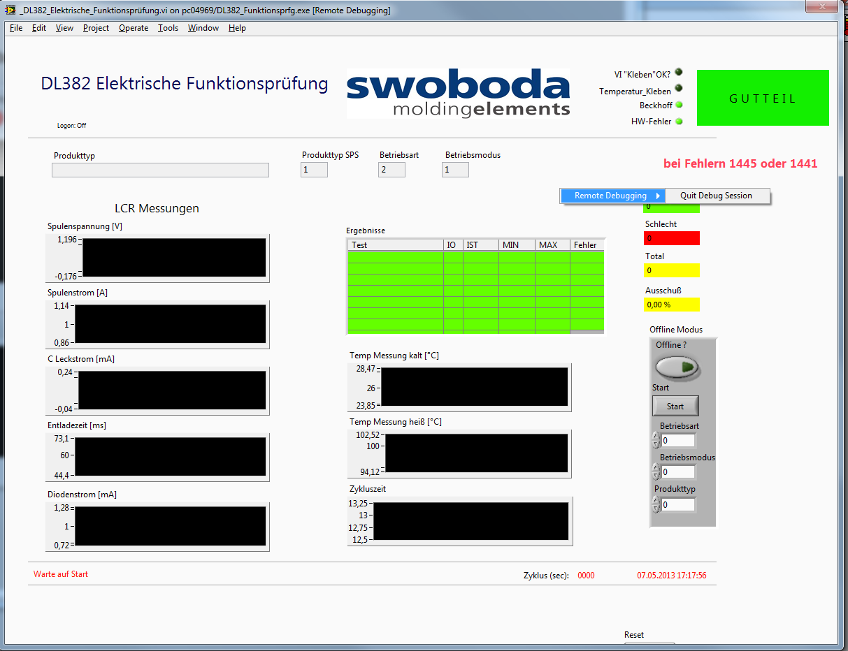
I have an executable running on a target that I want to debug. I enabled debugging in the build properties, I enabled debugging in vi properties. I can connect from the development computer to the exe.
But the option to switch to the block diagram is simply not there (see photo). I know I am a first not who has this problem but I couldn't find an answer.
Without being able to see the block diagram, a 'debug function' is totally useless!
If anyone has an idea it would be greatly appreciated. Thank you
Hi peter,.
It is a known problem and a request for Corrective Action (130070 CARS) was created and reported to the Department R & D. looking at through the notes in the CAR, he must fix it in LabVIEW 2012.
Workaround solution: Debugging applications with menus on bar
-
LabVIEW 2015 scrollbar bug on block diagram
Hello!
I'm using Labview 2015 SP1 Professional. I use windows 10. Whenever I have do an action on the block diagram I get annoying move right on my scroll bar. Does anyone else have this annoying "feature"? I tried on three different computers and evertime same also on windows 7.
There was a bug with nested structures that had enabled ' automatic'. Try disabling the automatic extension on all of your structures.
-
What is the best way to keep the block diagram / cleaning of façade?
Hello
I'm relatively new to Labview so I'm not able to say if I'm overloading my programs or make my too crowded block diagram. I was wondering if there was some ways to tell if I can simplify my programming just by looking (perhaps only experience contributes to these things)?
I enclose my VI here. Currently, she is able to monitor the voltage and current of two engines. On the screen, you can see an indicator with the voltage and current values and there are cards that can display signals of different engines with a menu drop-down.
The façade is pretty clean, in my opinion of novice, but the block schema seems messy to me, just at the first glance. I foresee a problem occurring in the future however. In the future, I will have the VI to monitor 50 engines globally. All of the programming will be the same as the one I have now, but it will have 50 indicators and unfortunately 50 times just about everything. I would like to avoid this, but I don't know how I did.
I use a USB-6009. I use its four differential inputs to monitor the voltage and current of the two engines. In the future, I will get more units DAQ (25 in total because 2 motors can be monitored for each data acquisition). The new Renault will help will help with more resource space, but I think things complicate with the added option of 24 more Assistants of data acquisition (as used in my code).
Thanks for any help you might be able to provide!
Usually, it is above all the experience that will teach you the best methods for making your code to do pretty. I don't know anyone who is proud of his first application of claws. There are some resources out there to help with best practices, as that group on ni.com, but you will learn most of your own development.
Your façade is superb. FPs in general really are to you. You can do it as ugly or pretty as you want. When you have a few controls in duplicate and the Group of indicators, you should use clusters and berries to simplify. You can use a bit of cleanup in this regard, but not much. In addition, I personally hate read red text unless it is a warning any.
Your block diagram could use a little cleaning in a sense of modularity. You have a lot of repeated code, which you might consolidate in to a Subvi, which is used in multiple locations, or in a loop For. A general rule is to keep your block diagram within a single monitor. You should not scroll. Your application is quite simple, so it is difficult to BUMBLE

Here are a few details on your block diagram:
- Click with the right button on your devices on the block diagram and uncheck the "display as icon". You are welcome.
- Operations on each waveform "(x*2-4)" / 16 in double ": create a Subvi and/or run the waveforms through a loop."
- You do a lot of 2-element arrays and then indexing. Just replace the ones that have a Select node based on digital.
- All your code runs every time, including the knots of your property at the bottom, which is not necessary. As you learn LabVIEW architectures, you will learn how to get around this with the initialization and the output of code, but for now, you should put a case around those structure for only when the engine numbers change.
- I don't know how you're timing your main loop, but you should put a delay in there because you don't need the DAQmx node shoot as fast as your CPU will allow.
There are videos of intro free that you can watch to learn what OR think in terms of coding and teach you some of the basic features and such. Here's a three-hour course, and here's a six-hour course.
-
Impossible to select and place the Instrument Driver VI icons on the block diagram
I am trying to automate some of the RF measurements using a Rohde and Schwarz Spectrum Analyzer. I downloaded the Rohde and Schwarz spectrum analyzer pilot named 'rsspecan' version 2.6.1 for Labview on Rohde and Schwarz site to use in my version of the software labview 7.1.
I copied the files in the appropriate folders in the Labview software on the C drive files. I am able to access those files through the functions---> Instrument I / O---> range of Driver of instruments in the Labview diagram, but when I select the VI icon that I want to put, I am unable to place it on the block diagram. Instead of hovering under the cursor by clicking on the VI icon, by clicking on the icon of the VI has no answer whatsoever.
Any help would be greatly appreciated.
Thank you
Thank you very much for the help.
So, is there a way to get the above mentioned pilot online Spectrum Analyzer, which will be also compatible with LabVIEW 7.1, so that I don't have to go through the conversion of version Board?
Thanks again,
Vivek
-
Can not see block diagram of an auto run VI
Hello
I have an old and dirty VI which runs automatically when opened. I don't see the block diagram because when I stop it, LabVIEW stops. There is probably this function of 'evil' LabVIEW to stop at the end.
Is there a way to avoid this behavior?
The VI wrote some time in LabVIEW 7.0.
Thanks for the help!
Vincent
Drag in a BD to another VI and double click on it from here or...
Find one of the SCREWS he calls and break first or
There may be other ways...
Ben
Maybe you are looking for
-
Firefox version 23.0 on MAC OS 10.7.5, question, Fedex track page does not completed - can't keep
can't use firefox to track the package on the web page of fedex, just start happening (mac os) André byczkowski [Personal information deleted by the moderator. Please read the guidelines and rules of the Forum, thank you.]
-
MacBook Pro hangs (black screen). How can I fix it?
Hello! I have a MacBook Pro 15', with the 10.6.8 System. About 1 year and a half, the screen started to turn black from time to time - quite often in fact - and I need to restart the computer. He stopped for a while when I spent of Chrome for Firefox
-
What happened to repair permissions w/El Cap?
I liked repair permissions & miss it! Why it was decided to remove it from El Cap? Now, in my opinion, the new disk utility is really heavy and not intuitive. Thank you Kate
-
How can I see what images are associated with my albums?
I create albums for various subsets of my photos and I would like to see what those who are associated with what albums. And those who may be associated with several albums. And who is not associated with albums.
-
Cosmetic glitch of Boolean properties window
When you select 'Properties' from the context menu of a Boolean control, the following window opens: Note the location of the checkbox "show the Boolean text." It can be expected, but I doubt so.