block of EEG using labview diagram
Tags: NI Hardware
Similar Questions
-
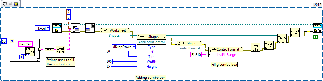
How to display the drop-down list box in MS excel by using labview report generation toolkit? Please post the block diagram of the code so that I can able to generate from the drop-down list box in excel with the menu drop-down...
Like this. (edition, use the reference forms instead of the reference to the worksheet)
Ben64
-
How to put two diagrams using Labview 8.5?
How to put two panels before programming of a front panel diagrams using labview, so that I can make acquisition of multi front panel only once running?
veceeeee wrote:
How to put two panels before programming of a front panel diagrams using labview, so that I can make acquisition of multi front panel only once running?Select all the code in the block diagram of the second VI and stick it on a blank area of the diagram, the first VI.
Now go to the face before of the first VI and fix things as you want. Throw the second VI.
According to the code, you may need to make some changes in the code (e.g. make sure two code segments to stop when you are finished). I assime you speak toplevel about two screws that are not called other screws
-
[Labview FPGA]: block of memory use Xilinx HDL integration node
Hello
In my project, I would be developed my own VHDL module and integrated in my project of LV FPGA with a knot of integration.
But for an evolution of my code, I wonder if it is possible to use in my own code VHDL, Xilinx library (as a block of memory).
Thank you.
You can use any Xilinx IP (or IP and others) in your external code. For example, if you generate a block of memory using block memory generator you can instantiate this IP in your own VHDL.
-
Register the event on the target in real time using LabVIEW 2012
Hi all,
It seems that LabVIEW 2012 RT does not support user events. Screws are not in the range of function and the help of LabVIEW says that it is not supported. In LabVIEW 2010, everything seems fine.
That's happened? We need this feature.
Thanks in advance.
Hello
Thank you very much. We will use this workaround, which is not a lot of work if you know what to do. Develop a VI on workstation and the execution of switching left target to the low edge also implements the correct block as well as feature diagram objects.
This can be fixed in the next patch-Patch because a lot of users could by irritated by this behavior?
Thank you
Tyler
-
Good Aftrnoon.
My thesis is based on software developed by using Labview. Can anyone suggest the best way to write the main sections?
For example, how to describe the experimental flow? My ideas have been use explanatory, take the labview code print screens describing what each of the subVIs. Does anyone have experience in this field? Or if you can share a thesis based on LabView program written, it would be ideal for reference. Thanks in advance
Kiryl
If your project markers are not familiar with LabVIEW, then frankly they should not be monitored a LabVIEW project.
In the same way that you would not be supposed to literally print code of entire base of a project in a written language, you don't need to go into the same level of detail with a LabVIEW project.
You can document your code with system diagrams, annotate them extracts of interesting pieces of code, writing pseudocode to illustrate the feature.
-
Complete equipment of simulation using LabView, Multisim, and MAX (easy answer accepted!)
Hello, all!
Sorry, I'm new, but I checked around for a definitive answer on this, but I'm not 100% sure. I learn LabView for a physics of upper-division course. We use hardware (DAQ - MX) and a mixture of laboratory equipment - mainly stuff such as voltmeters, oscilloscopes and test setup with simple components. I also work with NIM instrumentation, but that's secondary to my needs here. So, when I'm away from the school, is it possible to make a complete simulation of my classroom work using LabView, Multisim (for my model) and the measurement and Automation Explorer (for the acquisition of data-MX)? I know I can create a circuit and drop it in Labview, but I'm not sure on the acquisition of data. I hope for what is a "seamless" reconstruction of what I do in class. I can't take a simple 'yes' or ""; as long as I know it's possible, I can find the solution.
Thanks for the help!
I wrote 'sim' screws in many situations where I need to work away from the hardware store. I think that MAX has a few features, but you may be limited in the types of signals, you can simulate.
For my sim screw, I make a copy of the original VI with ".sim" added file name. I also change the icon in a characteristic way to identify the version of the sim card on the BD. In this way the two VI have the same connector pane and are interchangeable on the BD structure. disable the diagram can be your friend here. Inside of the VI of sim, I generate the signal in any form I want. You can also add additional if necessary controls.
Lynn
-
Control CMD (command line interface) using Labview 2011.
Hello
I'm trying to control software that has an interface to command line using LabView 2011 but I have problems when reading the information.
Is attached the VI I created so far, but it is not working properly.
Problems so far:
1 - if I use ReadLine(), it blocks showing no error and nothing else.
2 - ReadToEnd () same problem as the previous line, the software hangs just at this stage.
3 - if I compare the response of the "peek" in waiting for the - 1 indicating there is not more character, the hook of software as the previous steps.
You have some clues as to what might be wrong or another way to 'control' the CMD to send messages, read and send messages, etc...
Thank you very much for your help.
I've done it before - I posted about this on the forum here: https://forums.ni.com/t5/LabVIEW/How-to-open-close-and-monitor-a-application-xyz-exe-using/m-p/32511...
I did also wrap in a library at a given time and post it on the forums, but I couldn't find this particular post.
-
Screenshot of Tektronix MSO4104B using LabVIEW
I am trying to acquire a screenshot of an oscilloscope Tektronix MSO4104B using LabVIEW. I am currently able to collect data from the device and have a waveform displayed on my front of VI. However, for various reasons, our preference is to capture the actual screen shot of the scope.
I have reviewed the reference for programmers for this camera and have done countless searches on Google for an answer, but have not been able to find a solution. It seems that a few people were able to reach on OTHER Tek scopes by sending a hard copy through the port of communication (GPIB, USB, Ethernet, etc.), but according to the reference of programmers for this particular device, it seems that he will send a paper copy of an installed printer, rather than simply as a stream of data to the port which can be read using VISA controls.
The other solution I've seen is to record the screen turned to a flash drive, and then copy the file via the port to the PC. However, none of these solutions seems to be available on this device... it's one of the more advanced scopes makes Tek... I can't believe it's so hard! Help, please!
-
waveform, with an average of results using labview to O-scope
Hello fellow engineers! I'm a first-yeargraduatestudent in CHEE at the University of Houston. Basically, I know nothing about labview. I am trying to program an application that looks like this - I collect a waveform of the signal of O-scope. This waveform does not change its characteristic shape. I need to find the wave form average of waveforms of N (100 for example). Thus, the slight changes (or noise) in the feature of form during the period mustbeaveraged out and I need to have a resultant waveform that represents the average waveform over a period. So, basically, I'm collecting the wave several times (for example 100) on a single period. The O-scope that I use now is Tektronix TDS 2024 B. It communicates with the computer via USB. The version of labview is 8.5. For now, I am able to communicate with the computer using our o-scope through labview. I already downloaded the driver of instruments of your Web site. It turns out that the program can give me only the average result I can get directly from o-scope manually. I need to have more say on average (100) using labview. I wrote a program that relies on the instrument driver that is downloaded on your website (for loop part is average, the waveform). The program that I modified and an instrument driver are attached. The program cannot be fully open, if the driver is not put in the right place in the labview (under lib inst.) When I run the program, the average waveform does not appear on the front panal and signal waveform file is not saved correctly. Is there someone can find where I did wrong and it develop for me? Because I barely know Labview, it will be even better if you can add an image or program that you have changed. I'm waiting for your creative ideas.
With the best regards,.
--
Weiye
-
I want to send data using labVIEW to arduino using write visa and the process and to take action using arduino. After that, I want to arduino to send out necessary via a serial port to labVIEW which should be read using visa read and store in a chain. While I am able to write or read both individually, I can't do it consecutively. I used advanced read and write vi for checking my code, but nothing is helping. The wrong bed 'time delay before execution. " Please let me know where I can go wrong. Also is it possible to write code for hx711 using labVIEW
1. you need not "\n" on your orders println(). This command adds an end of line character already in the message.
2. you get the error because you have a loop around your reading. After the first reading (well technically, the second because of you add an extra line end character), there is nothing left in the port. As a result, you will get the timeout.
3. you should really consider using a Structure of the event. This way you just don't write and read when you press the Write button and you can also use the structure of the event to make the loop to stop. I also go up to close the port inside the stop-> value Change event.

-
question about labview diagram
Hi all
I'm working on labview with fieldpoint modules. Why can't connect me FieldPoint i/o Point constant directly to reading of the (polymorphic) FP? He said "I have connected 2 terminals of different types. But in some way, I found some manuals on NOR who said these 2 elements might in fact be connected. I use Labview 7.1.
Kind regards
Nicky
Thanks to you all. I solved this problem.
-
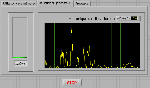
How to check the CPU usage and paging using LabVIEW
Hi guys,.
I build an application that is used to check the CPU usage and paging using LabVIEW. How can I do?
any help, suggestions or advice will be greatly appreciated...
Kind regards
Prashant
Hello
If you plan to build your app for Windows, you can use .NET classes. (System.PerformanceCounter), there is a simple example with LabVIEW:
C:\Program NIUninstaller Instruments\LabVIEW 2010\examples\comm\dotnet\SimpleTaskMonitor.llb
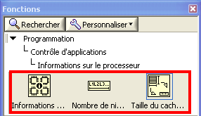
Also, you have several screws that you can use to verify information about the processor.
Kind regards
-
Programmatically insert step of ActiveX/COM using LabVIEW
Hello
I would like to be able to create sequences like the one set using LabVIEW.
This sequence has only 2 steps, a LabVIEW VI call and an adapter of ActiveX/COM call.
I was able to do using an adaptation of the code here: https://decibel.ni.com/content/docs/DOC-36337
However, I am struggling to add the step of the ActiveX/COM.
Any help would be welcome.
Thank you
Of course, there is a way, if you look for it

Since you have an existing 'Step' class object, you can also get a 'Module' object for her. Subsequently, you will need to specify that it is an ActiveX module. If you do not know which - probably you need to get the object 'map' somehow... Our case is simpler, so just cast to the ActiveX module and... to set certain properties like ServerId, ActiveXReferenceExpr and so on.
I've attached an example for you. Interesting thing is the ServerId - I just read this chain of the TS for similar action and reused it here so do not ask me how to get automatically
You will need to complete your 'properties' as 'file' - but I'll gracefully leave this work for you =.
Best regards
-
Time real ADC/DAC for SMPS by using Labview and USB
Hi all
I asked the Sales Department of this same question, so here's a two-pronged approach:
I am reserching a control algorithm for power switching, and so far, its performance simulations seem to be good. Now, the goal is to implement the circuit from the experimental data.
I've seen several NI USB DAQ boxes that seem to have the performance, I'm looking for (for example, the box USB-6211 a sampling rate and resolution I need).
The control algorithm uses the following mathematical functions: add/sub/mult/div/exhibitor and derivative/integral.
My question is this: is "strong enough" Labview take four-channel data 250Ksps, crunches the numbers in an equation and spits out the answer to an analogue on the channel, while time REAL? I'm looking for a rate of analog output of ~ 100 kHz.
Thank you for any suggestions you have!
-Rick
Hey,.
So if you were trying just to perform an input or output, then the box USB-6211 would certainly be able to treat it as the machine clock could manage the inputs/outputs, no software. However, what you are wanting to do, basically a feedback system, he will have to avoid (at least to a USB device) because you need to be able to specify Active which is the output. So, for this reason alone and the fact that you want out of 100 kHz, this device and the USB devices in general will be not an option any what software you use, LabVIEW or otherwise. On another note, you want to make sounds more like live update, not in real time, which is more on the jitter. Bottom line, for these kinds of requirements, you might need to move to an FPGA card, something like the NI PCIe-7841R would work. It's more expensive, but for your needs, FPGA will be the only option and it comes down to the latency of the bus, but also the response time of software. With FPGA, as shown in the first scheme of the following document, you basically close your software through hardware loop.
Basics of FPGA
http://www.NI.com/white-paper/6983/en
-Ryan S.
Maybe you are looking for
-
I created my iCloud years ago and would appoint as a more basic e-mail address but I get a lot of important emails on this account. I don't want to lose all my iCloud things related. Any information would be appreciated, thanks in advance!
-
L850 satellite are not compatible with windows 8!
I checked Windows 8 Upgrade - models supported on this site:[http://gulf.computers.toshiba-europe.com/innovation/ar/generic/windows8-matrix] I have not found my model L850 Satellite compatible with windows 8but I found my compatible part PSKDLV numbe
-
HP pavilion g7-2247us: hp pavilion g7-2247us Win 10 updated Wireless drivers
Hi I can not capture 5G signal of Time warner cable. I get the normal signal fine. Time W says I need a driver of upgreded to have superior internet modem. Someone knows how can I update this windows 10 w problem Thank you Carl
-
How can I recover pictures photo file numbers?
I seem to have lost my iPhoto file numbers when I upgraded to the Photos. Is there something that I forgot to do so, and if yes, what can I do to get these numbers? Thank you!
-
HP C7280 All in One printer: HP Scan of the error using HP C7280 all-in-one printer
I was scanning documents successfully until recently. I use a Mac with OS X 10.7.5 and receive the following error message when you use HP Scan. Cannot perform the analysis because another program has control of the HP imaging device. Try the follow