BNC-2120 thermocouple CCM with M6289
I try to use my of Ic CJC of BNC-2120 thermocouple sensor to measure temperature, but I'm not in a position to acquire it with mass M6289 endpoint device.
Whenever I do the labview program using the DAQ assistant, using ai1 as (by default in the appliance) physical channel and ai0 under the Ref. temp for CCM, it gives error daq this task is not specified.
I don't know what the program if 6289 can control the temperature directly probe or not.
Please help me in this regard.
Concerning
Anurag
Tags: NI Hardware
Similar Questions
-
Outputs analog BNC-2120 to stop working randomly
I have a BNC-2120 Module. I have the analog outputs implemented with an Assist DAQ. I'm running a square wave, or triangle wave at a very slow pace (.35 Hertz). I'm tracking signals with a waveform graph just before going to the modules DAQ help. The system works well anywhere from a few minutes to 25 minutes. The results seem to just stop working, but I still see the signal on the graphic display of waveform. I think that the BNC-2120 module has some questions. Someone had a problem where the output just stop working? I look in my program of VI?
Hi gwing,.
There could be a few possibilities that could go wrong. Could you upload your code? DAQ hardware do you use with the BNC-2120?
Best regards
Jonathan
-
Analog triggering on PCIe-6251 using BNC-2120 on Mac Pro?
Hello all-
There, does anyone know how an analog trigger using a PCIe-6251 card connected to a box of BNC-2120 interface? I am running LabVIEW 8.6 on a Mac Pro OS 10.5.6 and my VI of analog data acquisition seems to work but hangs up waiting for a trigger. The trigger analog signal must be applied to the terminal APFI0 and the BNC-2120 contains no connector with this name. On the M-series cards, APFI0 corresponds to pin 20 on the map itself, but I was not to locate any information that shows how the pins of the connector BNC-2120 connect internally to different spring on its façade and BNC connectors. Sales people NOR recommended the BNC-2120 as the correct one to use with the PCIe-6251, interface box so I think that probably one of the many connectors on the front panel of the box is wired to pin 20. Am I wrong? I spent hours to connect signals to the box in the hope of getting a trigger, and nothing has worked yet. To make matters worse, reviewing the VI to trigger a data acquisition using a TTL signal connected to all of the PFI 0... 9 connectors on the BNC-2120 just causes of VI to give undefined error message ' specific 89136 route cannot be met because the hardware does not support it.» The specifications for the PCIe-6251 indicate that a digital trigger should be possible through the PFI connectors, so it's a puzzle. I have an interface BNC-2110 box in the case which turns out be a solution, nothing about it is named APFI0 either. Any suggestion would be of interest. Thank you.
-Ken1
Hi Ken,
Unfortunately, the BNC-2120 doesn't have a connection available on the APFI your M series line. The BNC-2110 has this connection available.
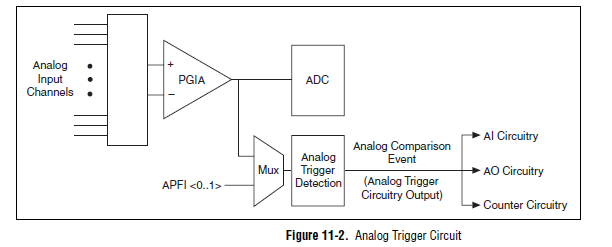
A possible workaround is that you can trigger off channels of analog inputs as well. Here is a screenshot of the M Series User Manual that shows the analog switch-off circuits:
There are a few caveats to trigger off AI channels (mentioned in Chapter 11 of the manual)
If you use a trigger to start, the analog channel that will be triggered off the coast of must be the first string in your scan list.
If you use an analog input as a reference or a relaxing break, it must be the only channel in the scan list.
I hope this helps!
Best regards
John
-
Angular velocity using the entrance of counter BNC-2120
Hello
I'm trying to measure the angular speed of the motor shaft with an angular encoder connected to counter input BNC-2120.
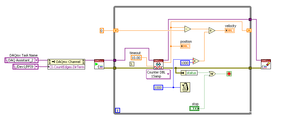
I found this file vi in the forum in a discussion by Macdonald and duy.
I'm doing the same... and I'm in the form of data values. but please can someone help me because I do not understand what degree or radians data of position and speed too if it is in rad/sec or deg / s etc...
the iam encoder using 3600 gives impulses /revolution. Is it possible to graphically display the position / data speed while the vi are running.
Kind regards
ruser.
Hello Fesmi,
No change is required for the counter 0/connections to your encoder. You will use 1 meter unit NOR as the sample clock Source i.e./DeviceName/Ctr1InternalOutput. Version of LabVIEW 8.5 of the example has been attached.
Kind regards
M Ali
Technical sales engineer
National Instruments
-
I have two units of Kistler and gives the same result, I use some old amplifiers Type 5001 also tested 2 different amps and still the same problem.
So that's why my temp senitive signals both and seems to be hook on one of the channels of strength?
Thank you very much!
very weak signals tend to do. Part of the load of the amplifier is always present.
So to read weak signals before the biggest or adding a zero volt signal inbetween will help.
Good luck
-
Compatibility of the Thermocouple K with USB NI 6008
Hello
I have trouble choosing what to buy to make temperature measurements with my already purchased NI USB 6008.
I intend to use LabView to work with these measures of temperature and link them to other measurements with other sensors using the same NI USB 6008.
After some research, I think I'm going to need a K Thermocouple as this one: http://fr.rs-online.com/web/p/sondes-de-temperature/3428899/
But my question is: I'll be able to use it, simply cut off the connector and connecting the cables to my NI USB 6008, or do I have to use a special system like this: http://sine.ni.com/nips/cds/view/p/lang/fr/nid/208177
And if I need such a system, I'll be able to use measurements with other sensors on the same LabView?
My hesitation comes from this document: http://www.ni.com/pdf/manuals/371303n.pdf
Page 13, seems, I have to use 2 resistors to bind my Thermocouple K to my NI USB 6008, but the use of such a system will make it difficult to obtain certification (this system will be part of a machine).
Hoping you can help me,
Patatelover, Polytech' Clermont-Ferrand, FRANCE
PS: Sorry for my English, I am not native...
The 6008 is not appropriate for the measures by thermocouple - see this article for details, but in short, you would be able to measure at a minimum resolution of 8-9 degrees with a precision of 30 degrees.
You must use either a USB as the connected USB-TC01 thermocouple module, superior performance DAQ (with a range of smaller / more high resolution) or use a C-Series Thermocouple module.
-
Several Clusters of CCM with one box of 3.1 (5) unit
I currently have a single handler calls 3.2 (2 c) cluster that connects to a single unit box 3.1 (5). I need to create an another CCM cluster but want to use the same box of the unit. Is this possible? Are there aspects license I need to consider? I know that I can add configure additional CCM in the FST of unity, but don't know if that's all I have to do. For MWI, have I not need to specify which subscribers will use which CCM cluster? If so, how?
Thank you, Glenn
Yes - Here is a white paper on this operation with CM 3.1 and later versions:
http://www.Cisco.com/en/us/products/SW/voicesw/ps2237/products_white_paper09186a00800872c8.shtml
-
Several analog inputs seem to change any of the other (details DAQ: 2120 BNC and 6062E)
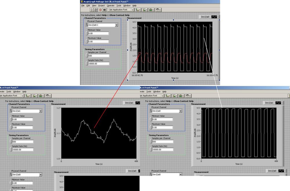
I use the BNC 2120 DAQ board connected to the data acquisition card 6062E to record two analog inputs. An entry is connected to ai0 and the other at ai1. Example vi: "Acq & graph int clk tension" has been used to measure the two entries with the value read NChan NSamp vi (channels being dev2 / ai0:1). The output is the top graph in the image. However, this seemed a bit strange to me that one of them should be modulating with a different frequency. When I record both entered individually (two in low pictures) they are indeed different since the entries shown in the top graph.

Why this would be the case, and how can I overcome this to measure the real signals?
Thank you!
The E series card takes the samples as soon as possible. Thus, for example,.
If you have 16 analog input channels but you only read of
channel 0 and 1, the map will show the channels 0 and 1 right
After and then wait 14 'ticks '. What's that little run-in
the origin of the afterglow.
I think you can get the card to wait a certain
number of ticks with a property node. I have attached a screenshot. You
can find the property node in the palette of functions >
Measurement of e/s > NOR-DAQmx > node Timing. Expand it
Property node so there's two entrances. The properties are in
Left click on the node and going more > converted >
Its properties delay units and sampling clock delay and delay that
you want.If the phase is important so the above is not the best
the option because it causes a delay in phase. So, if you need true simultaneous
sampling, then you will need different hardware. The S series is everything
simultaneous sampling.Or, rather than the Delay property and delay units, try the Rate property
find more > converted > rate.If this is not
work either, you can move the second signal source to, say, AI8 and
Connect everyone to the ground. Readings for these, but just do not take into account
the data. In this way the ADC will sag to the ground at the time where that can happen
the second string in the way so that you should not see this frequency
ghosting on the other channel. -
Noise thermocouple with PCI-6230
What level of noise should be expected for a K type thermocouple used with an acquisition of data PCI-6230 and a map derivation CB-37F-HVD? I read the data with LabVIEW and Daq Assist module on the setting of the thermocouple and the noise see of +/-1 ° C. For a type thermocouple K 41uV / ° C is 3 times the 6230 noise expected (13 uVrms) runs around 0.2 full scale. I think it should be more stable measures or is this a normal behavior?
http://sine.NI.com/DS/app/doc/p/ID/DS-31/lang/en
Thank you
Dan
This level of noise is expected. To improve, you can use a card with a noise filter. A dedicated thermocouple module would also work, but this includes a noise filter as well.
-
How to make your own Board BNC connector for 37 pins PCI-6010?
This is first time I am doing data acquisition and the BNC-2110 present can be connected to PCI-6010. How to make a Board for it?
I'm not sure what you mean by "some"; The BNC-2120 exposes all channels HAVE and AO on connector 0 of a standard feature of E, M or X series.
- Eight BNC connectors are for eight differential channels of I. For example, for the BNC connector labeled 'I 0', the Center connects to the 'I 0' pine and the outside connects to pin 'HAVE 8'. (The BNC-2120 probably would not be a good choice for someone who wanted to use the channels in unbalanced mode).
- Other two is for the analog output; the centres are ' AO 0' and 'AO 1' and transmissions are related to "AO GND".
- There is another connector BNC for PFI 0; all other PFI (with the exception of the 10, 11 and 15) are broken down as screw terminals.
- Other BNC connectors connect what either directly (the unit is powered by the + 5V line but otherwise works autonomously, and the "user defined signals' are connected to terminals to adjacent screws).
It seems like it wouldn't be difficult to have a cable that was going on a PCI-6010 the 37 pins on the connector 68 pins on the BNC-2120. I'm a little curious as to why we do not have one. Possible reasons off the top of my head which may explain why not:
- cards PFI/description would be a mistake (for example, on a series of E/M/X ' CTR 0 SRC "PFI 8; on the 6010 is PFI 0.)
- No digital lines (E/M/x series P0.0 P0.7 via are independent; on the P0.0 6010 P0.5 and P1.0 by P1.3 are shared with PFI lines)
- Confusion about being able to connect to other devices that we sell with connector d - SUB 37 pin, but who do not use a compatible pinout (for example, the PCI-6239, PCI-6510 or the NI 9237). Here again, a PCI-6703 also uses a 68 connector pins, but has a completely incompatible pinout as well.
But it seems that those who would be pretty easy to deal with, because it is useful to be able to connect to the BNC-2010. Maybe it's an idea for the Exchange of ideas information Acquisition?
Anyway, if you want to have pushed BNC for everything on your Board of homebrew will need you:
- 8 or 16 BNC connectors to HAVE, depending on whether you want single-ended or differential. For differential, the centres are GOT by AI 7 0, and transmissions are AI by AI 15 8. For asymmetric, the centres are HAVE 0 through 15 AI and transmissions should all connect to GND AI.
- HAVE a sense (I think that you only need this if you use channels Nonreferenced Single - Ended (NRSE). See also: noise considerations for analog signals and field wiring.)
- Two for AO (centers are AO 0 and 1 AO, outers times connect to AO GND).
- Ten for PFI/digital lines. Outers will connect to GND D.
Up to a maximum of 29. You want maybe less, depending on your application.
-
Output TTL triggers analog input with PCI-6251
Hello, I'm new to LabVIEW and have a question that I hope I can get a response on this forum. I am currently using a PCI-6251 DAQ card with a block of connection BNC-2120. I would like raise an event on an input, for example a sine wave, which is connected to AI0 analog. Then I would send a TTL pulse train via the digital output. What I'm describing can be better understood by the images of this link:
http://zone.NI.com/DevZone/CDA/tut/p/ID/3017
In the tutorial page linked above, they do mention the card PCI-6251, but when I read the specs and compared, 6251 also has analog and digital Board, trigger functions, as well as digital I / Os... so I think he should be able to do what I want it to do. Can anyone confirm this? If anyone could help me by providing a VI that could do what I ask, just to help me get started, would be greatly appreciated. Thank you!
Hello!
Please post on the Forums OR! My suggestion would be to use build it digital Pulse - Retriggerable.vi found in the Finder for example of OR. Open LabVIEW, go to help > find examples > input/output equipment > DAmx > generating digital pulses > generate digital Pulse-redeclenchables. Change the type of trigger for this departure vi > Analog edge and make the source one line APFI (pin 20 of your card is APFI0). This will generate a pulse based on an edge similar to a level that you specify.
I hope this helps!
-
Triggers of analog input output meter with delay
Hello!
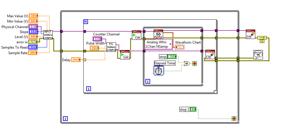
I am currently using a PCI-6251 DAQ card with a block of connection BNC-2120. I have a VI (one that is attached to this topic) that will essentially be an analog input signal and produce digital impulses from the output of the meter to each instant trigger. I am also able to define a series of delay values such that the delay will update automatically each at intervals specified by the user or when you press the stop button. I wonder if there is anyway to change this program as the time-out value will change every instant release. So, for example, in the first trigger a pulse is produced 0 second delay, then immediately when the next instant relaxation is reached, a push will occur with a 0.1 second delay, etc... And I want that the series of the time-out values to keep looping. I tried to use my current VI, with time to stop at each iteration to be less than half of the period, so theoretically it should go to the next delay value in the next instant trigger. Then I tried to put a certain time-loop around it to keep the job going, but it doesn't seem to work. I've attached a screenshot of my attempt, please let me know if this is possible, thank you! To see what each part of the VI in the screenshot, please see the screws attached, thank you!
P.S. for the VI that is attached, the analog input signal is 281Hz, the pulse width is 2.5% of the period and the delay is in the stages of T/20.
No worries,
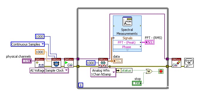
Please see the attached block diagram image. It is important to wire terminal on the Read.VI DAQmx acquire in a constant to the number ofsamples. This will force this function to wait until many samples are available in the buffer. In my example, you will get 1000 samples per second (because my rate is 1 kHz). and these 1000 were submitted directly to the FFT. What happened for example of you, it is only because you have not specified the number of samples to read, it is by default (-1), which means that the DAQmx Read.vi will pull all the data that is available in the buffer at the time. So if you had only 2 samples in the buffer that your FFT will have only two samples on average and as a result it will fail. Try this and it should help!
-
Can not see my RS232 ports on my PSC-2120
Hi all
I have a job 2120 PSC well with a number of modules. However, now I want to use the serial port on the cFP-2120 ability to control a syringe pushes. I checked the Max software installation, and I have no Visa & NOR-Serial installed. When I look at the PSC-2120 Max, I see the LEDS, some selection of starters, DIP, but not one of the 4 ports series.
Any suggestions?
Thank you
Scott
Scott,
Because the CFP cannot run the NI-VISA server, serial ports will not appear to the MAX. It also means that the COM ports is not directly accessible via ethernet to a remote host program. For remote access, you must embed a vi who can talk to the port. You can use the network shared Variables to get data in and out of this vi.
If your final application will be all shipped, just write that your vi using the functions of NI-VISA and select the port you want to use.
-
Only $line0 of digital output NI PCI-6014 accessible, other lines do not react in Labview
Hello
I have a NI PCI-6014 card with a card BNC 2120 DAQ and Labview 8.6. I'm trying to transmit digital signals, but only the digital IO port $line0 responds to my orders, while lines 1 to 7 don't work at all in Labview. With the measurement and Automation Explorer, I can access all the lines and change their State. I also tested another card (NI PCI-6154) with another card (CB-37F-LP) and had the same problem there (only $line0 of the digital port0 reacted, others don't). I have attached the VI very simple, I used to test digital ports. If the problem is known and what can I do about it?
Thank you!
Good never mind digital ports do not not Boolean signals, except $line0, which strangely accepts integers...
-
Rotary decoder in real-time and 'pulse shifter '.
Hello world
I'm putting in place a rotating decoder for use as a shifter of pulsation by labview real-time.
Basically, this means I have two input channels (ttl-legumes, ~ high 20us) rotary engine. A channel contains a pulse at each CA (angle cranc) ° up to 12 kHz (increment). The other channel contains a pulse every 720 ° CA (the charge cycle, BDC_cc low break-even point). With this information a pulse to be generated on an output also channel ttl (high), which triggers my setup of measurement. This impulse must be moved in a programmable relationship to the entrance of BDC_cc, which aims at a table of regular measure.
I got it running by streaming the channel of BDC_cc until a rising edge is detected, then count the edges of increment to the designated trigger point and then generate a pulse on the output channel. The problem is that the late 70-120us exit trigger. In short it's too; a maximum error of ~ 20 is acceptable. Digital channels appear to work faster, so I put discarded Counter-based acquisition.
I'm quite new to LabView, so I'm sorry if the answer is obvious...
My purchase setup consists of:
PCI-MIO-16-1
BNC-2120
LabView 12.0
Max 5.3.1f0Widows XP
This configuration seems to exclude some options Labview offer, such as the external digital acquisition sampled or externally triggered by the acquisition in the base. A manual interpretation of analog inputs is way to slow.
I have attached my working version.
Any input appreciated woud...
John,
I only have a minute right now, but think I can play with a device simulated tonight or tomorrow.
I'm quite sure that there would be a clean solution clocked by material if you use a series M or X-series
Council MIO, but the older generation counters timers on the set of the E series do support everything which
You need. It's been a while since I had to rely on this generation of hardware.
I think the basic approach is to use the lunatics of angle as the clock pulse train that defines the
delay time of the pulse you want to generate. You could be "Timer" the pulse based on the real
angular position, helping you synchronize to a specific angle of crank. The question is whether and how E-series
counters of takes to support the generation of pulses triggered (or redeclenchables). If they are not, I would say that you consider
get new hardware DAQ which support this kind of trigger and you give a very precise pulse
implementation.
-Kevin P
Maybe you are looking for
-
iMessage actication fails in Iran
Hello Why on my iPhone 6s iMessage will not be activated with my phone number? My carrier is MCI and I know how this works, but why Apple have not found a way to solve this problem... cause it was OK before in Iran but its been a while now, this feat
-
DSC: IO custom Server: on the change of entry
I wrote a custom server IO VI using the DSC Module. Using NI DSM, I see the server status is 'Active '. Once again using DSM, I change the value of the control which is supposed to trigger the VI to run, but it does not run. What Miss me? I managed
-
I can't get this username entered with success because I'm limited to only users on the computer, I'm trying. I have Windows XP off file sharing simple. Both computers running XP Pro and I can share the folder, but it is open to ALL. Is there a wa
-
XOOM: Why SD card does not work on my Verizon Xoom?
does anyone know why my xoom is not reconizing micro sd, thanks
-
Port on which I plug my speaker in they is such a small side speaker plug - I have 6 ports
I have 6 ports row on the top is low pink blue yellow orange line black white that one I connect speaker in? I tried everything and still no sound yesterday very well worked unplugged today and not sons has not look to see where it was plugged in fir