Bouba plots by evil of FFT?
I built a VI to build MAG/PHASE plots using FFT of the range of signal processing. This is a small VI & seems a bit simple. However, to check if everything is working correctly I built a 2nd & 5th order pole fictional system that I know that the transfer functions: 10/s+10(1/(s+0.5)+1/(s+0.5)+1/(s+0.5))+1/(s+0.5))
2nd order system:10/s+10(1/(s+0.5) Note that these 2 systems are in exponential decay in the time domain.
It seems that I solved my problem. I have been using the FFT properly throughout. I had my incorrect analytical model. The FFT told me this throughout, but I doubted that I was with them properly instead of questioning my analytical model.
Tags: NI Software
Similar Questions
-
Hello, I have a problem. I need to draw on 1 2 plots to compare their FFT. I want to have 2 plots with the same styles that you can see the locations named FFT2 and FFT3, but if I compare to the FFT plot one of them have line different style. Anyone can take a look at it?
This is the vi, but believe me it is easier to do it yourself...
Marco
-
Difference between FFT LabVIEW and Matlab FFT
Anyone know why there is a lag in the absolute levels of the results of the function in LabVIEW and Matlab FFT?
See the VI attached for an example of my code to LV.
Also attached is the plot generated in Matlab, which seems to be compensated by ~ 37dB.
This was generated by using the command "plot (10 * log10 (abs (fft (x))))", where x is the same as in the VI input array.
Thank you very much
Dan
I see you are using the VI of spectrum FFT which returns a unique range of face. To convert a transformation both sides (IE FFT) in one spectrum sided with RMS units there is a standardization of sqrt (2) / n, where N is the number of points in x (t). You can prémultiplier your x (t) by N/sqrt (2) and get the same results as Matlab. Or, you can use the FFT.vi so you compare transform to transform instead of spectrum to transform.
-
Hello
I'm tracing a FFT of find a different frequency of the signals non-periodic signal.
kindly help to plot the frequency and Amplitude.
attachment have given amplitude time Vs
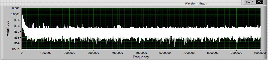
Is that what you see?
The image I posted previously is the same graph and the same data, only the maximum of the scale of the x-axis has been changed to 100000 of 100000000. Just select the maximum value with the type tool and enter the new value. This does not change the data in some way. It changes only the portion of the data that is displayed on the screen.
Lynn
-
Why Express PSD gives a different result of amplitude as FFT PSD?
Hello
When I use the express VI of spectral measures to trace the power spectral density, I get a different result than when using the FFT PSD VI. The data are the same but the amplitudes are different in the PSD plot. Everyone comes through this?
Thank you
Donners,
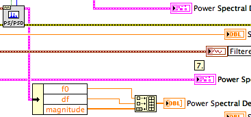
The PSD2 and graphic PSD2 are different because you are breastfeeding two extra points in the tables (t0, df). When graphic entry of data in the tables, they interpret not automatically information of t0 and df. Actually they do not yet receive this information. You must program the scales with nodes of property. If you simply draw the order of magnitude, the spectra are very similar.
^ ^ ^ This confuses only the chart!
The spectral forms differ slightly as the power spectrum of FFT and PSD.vi uses a default Hanning window.
Lynn
-
Hello
Before all sorry for my English, I'll try to do my best.
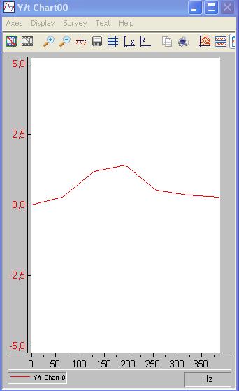
I'm analyzing a data acquired with a FFT, but I want to refine or reduce the frequency of each 'window' (I only want to analyze the 0-350 Hz region)
in order to see better where my maximum in the frequency domain is.
If you have an idea where I can edit this wide frequency in order to refine the plot, please tell me!
Thank you very much!
The sample rate determines the scope of the FFT calculation.
Using the Nyquist theorem, if you sample a 1000 samples per second, the FFT will calculate the range 1000/2 = 500 samples per second.
You NEED to taste at least twice the highest expected frequency in order to use the FFT module to find this frequency.
The resolution of the FFT module is determined by the size of the block. For the spectrum of amplitude by default, TFF will display a block which is also 1/2 on the incoming block. Size of block = 512, FFT block size is 256.
You can increase the resolution by increasing the size of the block and also by changing the size of the block to a number which can divide the sampling frequency. For example, if the
sampling frequency is 1000 and the block size is 500, the FFT output will have a resolution of 250 on a beach of 500.
You can use the data window module to change the block size - increase it to use more data and to increase the resolution of the calculation of TFF. Decrease that it resembles an interval of time smaller and lower resolution of FFT.
I hope this helps.
-
Hi all
I used a signal for a FFT analysis using DIAdem. I have used the following options available in DIAdem:
FFT (hourly)
Windows type: Rectangle
The FFT functions: Amplitude
Amplitude type: power spectrum
Third / Octave = No
Average of the amplitudes: none on average.
I have attached the raw data in an Excel file. In addition, I have attached an image indicating the amplitude versus time plotted in tiara on top. On the left side the data plotted using another software, while on the right side, the data is plotted to TIARA. The frequency on the x-axis is ok, but the amplitude on the y axis is not the same. I would like to ask if there is a way I can get the raw signal of amplitude with tiara, I think it's the normalization?
Thank you
Pepis21
Hello boutique,
Looking at your signal, the amplitude you want to achieve is not possible (unless you change units or you it multiply).
Imagine, if you had a perfect sine wave of amplitude of 1 you should have an amplitude of 1 when you perform the FFT.
Your maximum amplitude signal, you could get would be less than 100 (far 3.5E7)
Best regards
Andrés
-
I have already tasted the data of an input in the time domain signal. the signals are sampled by ADC and stored in excel file (about 16 K samples). I need to feed to the FFT VI for the plot of the FFT. I tried several bolts of FFT, but nobody does not accept data samples directly which is stored in the table 1 d. Any ideas? Thank you.
Hi ABM26,
Your input signal looks like a pure sine wave. You perform the FFT and get the amplitude. So you get two peaks in the result. I think it is the correct result. Why do you think the result of the FFT is false?
And I realize that you want to calculate what the power spectrum. You can use the Signal Processing > spectrum analysis > Power Spectrum.vi directly.
-
I'm figuring the FFT of several signals, I have used sine waves in the attached vi to highlight my problem.
I created 3 sinusoidal signals using signal generated express vi.
Sinusoidal signal 1: Fs = 20 Hz
Sine wave 2: Fs = 250 Hz
Sine wave 3: Fs = 500 Hz
I combined these signals in a table and fed in FFT Soectrum (Mag Phase) VI and see the results on a graph in the form of wave. I changed the property of multiplier of charts to the sampling frequency of the singal handset (1 sine wave Sine Wave 2 + Sine Wave 3) which is equal to 770Hz.
The plot of the FFT spectrum is throw up quite unexpected results. I expected peaks at 20 Hz, 250 Hz and 500 Hz, but I get crazy values.
I'm doing something wrong... ? Take a look at the vi attached please.
Stroke
Hi the shots.
You seem to be missing a few basics about LabVIEW data types as well as their manipulation...
You cannot add waveforms by adding berries to Y in a larger painting, you must Add the.
Play with the filter command in the attachment (to perform a control of it can make it easier...)
-
Hello
Im trying to understand our noise of a laser. My setup is Laser - detector-Oscilloscope. I read the signal using a GPIB and Labview program. I think that I must take the FFT of the signal produced but it gives me nothing. I plugged the output signal to the FFT.vi and the result is a peak at 0 (zero). I should al least see peak around 60 Hz (light), but I can't. My sampling rate is 100Ksamples per second. Also, how can I see frequency on the x-axis of the curve of the FFT and what is Y Chart FFT plot?
Thank you
Yes. Without information from dt, spectral analysis function will assume a sample rate of 1.
-
I'm new to Labview. I need to plot the data (2 passes, one's time, x table, the other is the intensity of the signal, y table) provided by my instructor in the time domain, which I already did. Then I need to convert the data in the frequency domain. What should I do? I tried the FFT function for my table of y. But how do I know the frequency of informaiton? Of table x, I know it's sampling rate is of 2500 Hz. T = 40, N = 100, 000. the effective maxmium frequency should be 1250Hz, right?
And I also need to isolate the signal of 1000 Hz... I'm totally confused.
Hope you can help me. Thanks in advance.
John
Norbert made some good points - you must have a game and maybe get a good book on the signal processing (not specific to LabVIEW).
You're talking about the 'effective' frequency is I guess that the Nyquist frequency = sample rate/2. If that's what you hear, you don't have what about TI-just be aware that the maximum frequency that will show your power spectrum is sample rate/2.
You can isolate a specific time, the field in the way you mention, FFT signal-> zero spectral bins, you're not interested by-> inverse FFT, (not use FFT power spectrum for this). A standard FFT will put on a spectrum double sided, which is symmetrical to the time series that contain no complex numbers, so you will need to virgins at a given location on both sides of the spectrum - which is perhaps what you were talking about RE: effective frequency. Use everything (not only + ve half) to restore the original signal.
The method "virgins a bin and inverse FFT ' is not a 'good' way to get time series in a band for the treatment of the real signal for reasons I won't explain here. You use usually just a filter on time series, including LabVIEW provides several.
-

Hello
I have an image of size M X N (pixel).
Fisrt first saw the image of the location of path. Then I used Unflatten Pixmap VI to convert the image to a table. Now I need to find the D 2 FFT. I do the FFT by fisting the transformations of lines in parallel, then the transformations of the columns in the result of computing. For this, I have extracted the value on the resolution and gave him for your loop for (since there are N lines of the image.) Next, I calculated the FFT for these lines. The resulting table is transposed to the FFT for columns. Is the VI I did correct? Please see the attchement for the image.
How can I get the 2D - FFT plot?
Thankss
you had the right idea. See the vi attached for an illustration of a graph of the intensity of the fft and inverse 2D fft and photo poster.
-root


-
I am trying to trace the FFT of a certain number of waveforms, but I find that for some outputs simply return an array of "NaN" instead of the scale, with no indicated error. Looking at the data I see no significant difference that could cause this. anyone can shed light on the problem?
I watched the formula apparently used by the FFT vi in aid detailed and created my own version, and he experiences the same problem with the same sets of data. Fathom what happens, it seems to descend to labview randomly taking one of my input data values and its reading like "NaN" - a bad size and TFF any fate of NaN. Why is reading that entry as NaN but is a mystery, and yet he does it regularly because the same plots always failed.
I have attached the relevant vi to look, any help would be appreciated.
You were asked to see if the data included NaN and you do not. The last element of the third data series is NaN. I haven't checked the other tables because it is something you need to do.
-
Get the minimum frequency of three signals FFT
Hello
I put in work of a closed online using LABVIEW loop controller. There are three entrances of signal, the FFT of each signal must be calculated online and frequency spectra is the lowest to be detected.
The plot of the Spectra is attached...
Please advice on how to achieve...
Thank you
ruser.
-
FFT waveform (file converted from Matt file lvm) - how to overcome the error dt < = 0?
Hello
I use a lvm file after conversion of Matt file. I wanted to get the fft spectrum. I get this error message this dt waveform<>
How he overcome?
I have attached the matte file and the vi that I used.
Best regards
FESMI
The Forum is a bit special files that can be attached. Creating a zip file often works. Sometimes, you can change the .txt extension. If you change the extension, please indicate in your message which was the extension of the moose.
It seems that data in the file has a time column and a column of amplitude. The LabVIEW waveform data type is a cluster of a table of amplitudes (Y), sampling interval (dt), from the time (t0) and optional attributes. That's what the power spectrum VI requires as input. The t0 values is not used if the default is fine. the value of dt can be calculated by the difference of the two adjacent values in the time column. Given that the first value is equal to zero, the second value is equal to dt. Use the primitive to build a waveform of the palette of waveform. Expand it to view the dt element.
In the VI attached all lines is an indicator that contains your saved default file data. Graph XY plots that data. After subtracting the way to get rid of a continuous component, the data is converted to a waveform. The power spectrum is calculated and displayed using the same VI as in your program. It also uses extract several Information.vi tone for the frequency and amplitude of the main peaks in the data.
Interestingly, the lower frequency of the spectrum a harmonic of 60 Hz while the tops are almost sharp space 4 kHz ~ 100 Hz apart. The broad peak near 2.1 kHz does not seem to have noticeable components to 60 or 100 Hz.
How to avoid the Type of dynamic data (DDT)? Stop using screw Express! For reasons known only to EITHER screw Express a deliver their outputs via the DDT. Except when you open the block diagram of the express VI, there is no way of knowing what the underlying data structure on a thread of DDT.
Lynn
Maybe you are looking for
-
Noticed that there is a bulge on the screen of my iPhone the day before. I visited the Apple store in Waterloo today to help, but I got is the recommendation to pay for a new iPhone because I bought my phone more than 3 years ago. Apple "suggests" pa
-
HP 550 wireless and Bluetooth problem on win 7
Hello I had a problem with the wireless and bluetooth connection, since I upgraded to windows 7 x 64 The problem with the wireless, it's that I can't find not all devices wireless in range (even if I have a wireless router at 2 meters far from provid
-
Fatal error... System stopped. CODE: CNU02915FZ
I have my hp mini is asking me a bios password."Password check failedFatal error... System stopped.CNU02915FZ ". How can I solve this?
-
How can I solve the problems with the installation of directx on windows xp pro error
dooooooooooooooo
-
When I try to use the bing search engine I get an error 400 bad request and below (nginx)
direct ssearch does not work