Butterworth filter
I want to build a Butterworth filter with the node of the formula. What should I do?
We will do it step by step, and if you can correct me.
I have seen that the formula for the Butterworth is:
H (JW) = 1/sqrt ([1 + (f/CF) ^ 2N])
now, I know that the cutoff frequency is CF = 1 /(2*pi*R*C) where R & C are variables and selected by the user (that's what the professor asked).
So, if I write in the node formula this statement:
Tau = R * C;
CF = 1 /(2*pi*Tau);
FdT = abs (1/sqrt ([1 + (f/CF) * 2 * n]));
I got error. Why?
You were close. But your small loop inside the formula should look like this. Notice the perithesis around the 2 * n. You were just squaring. You should raise to a power of 2 * n. I've added an entry for the number of poles.
for ( f=0; f<1000;f++)
{
  H[f]=1/sqrt(1+(f/Fc)**(2*n));
}
Also, is there an absolute value in the digital palette. Use instead of the square and the square root.

Tags: NI Software
Similar Questions
-
With the help of a Butterworth filter without phase shift
Hello
I found this reference to the use of a Butterworth filter without phase shift http://zone.ni.com/devzone/cda/epd/p/id/2775 but I can't open the sample with LabView 2011. Can anyone help? The referenced file is attached.
Is there another or the best way to do this?
Thank you
Attached is a version saved in LV2009.
In such cases, you can validate the vi to the discussion of queries VI Upconvert.
Ben64
-
the power of the spectrum graph and butterworth filter
Hello
I am beginner in labview, I want to see the power spectrum of the sound samples, I want to see if there is any reason in these samples.
I use spectral measure, and then I filtered with butterworth filter samples. For output I using waveform graphs.
Before filtering the signal, I'm in the x axis of the graph between 0-22500 and the data mostly in 0-2500.
I've tried to filter using these values (fs = 1000 Hz, 0.125 hz = fl and fh = 500 hz) and the graphics almost the same thing but the axis of the graph is between 0-0, 5.
issues related to the:
What is the x axis properties? Why is different, but the graphics are the same?
Make the mistake with the program?
Hi Limavolt,
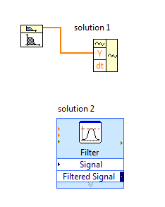
You have a problem with the bandpass filter VI, this VI generates only the signal of value i.e. table DBL. The signal is a cluster.
solution 1: you need to calculate 'dt' using the sampling frequency and use VI waveform construction to generate a signal's own scaling.
Normally, dt = sampling frequency/No. samples
Solution 2: replace the VI butterworth filter with filter VI express, this will produce signal without scaling.
-
How can I get the Coefficients of scaling for the Butterworth filter FPGA version
I am trying to program a FPGA application where I need to be able to change the cutoff frequency of the filter. I see that I can do a terminal for the coefficients of the filter on the VI express Butterworth filter, but how to generate the coefficients of different cut-off frequencies of filter? When I use the VI of Coefficients of Butterworth host-side small floating-point values rather than the large fixed point values I see on the side turns FPGAS.
Thank you
David R. Asher
Hi David,
8.5 or 8.6, there is an example of navigation that contains the Subvi design filter you need:
examples\R Series\FPGA Fundamentals\Analysis and Control\Filter and filter Butterworth Reconfigurable DC-RMS\Using-R - series.lvproj
In LabVIEW 2009, there is a new palette in my computer: Interface FPGA > scaling, with a new VI of Coefficients of Butterworth on this subject. Who will produce the coefficients quantified, you need in the format expected by the FPGA Butterworth filter.
Kind regards
Jim
-
FPGA Butterworth filter - why conversions to decimal fixed?
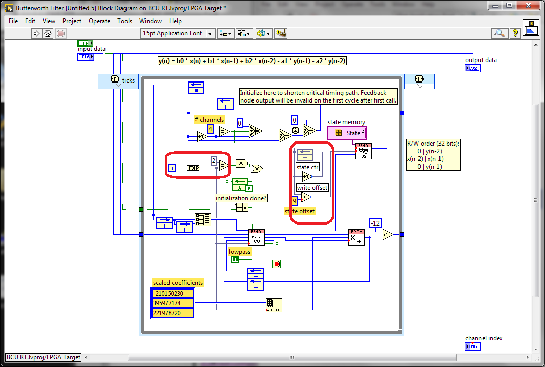
I was looking through the screw FPGA Butterworth filter Express and stumbled on this code (after conversion the Express VI into a Subvi and then by opening the front panel):
What is happening with the conversion to decimal fixed values that look like they must be integers (in the red boxes)? Why these conversions would be useful?
Here is the micro-optimisations to help the synthesis tools to minimize the number of bits used in these code paths. The iteration Terminal is 32 bits wide and also involves a logic to do in the face of what is happening when the maximum value is reached. We have seen some benefits from the reduction of this path to the minimum width required both that which is written. I think it is probably still the case since the compiler usually does not know how many times a given line will run with a dynamic stop like this condition.
The optimization of the meter width is similar, taking advantage of the fact that we know that we have limited storage space to use circular buffers power-of-2 size. Using the exact number of bits of the address allows us to implement a counter of reversal with no additional logic. otherwise, we would need to check the value, and add a mux (Select) to reset the counter when it reaches the maximum value.
Synthesis tools usually do a good job of optimizing the unused bits, but here are two cases where we can help them by being more explicit about what we really need.
-
How can I determine the best order to execute my butterworth filter at?
I'm low-pass filtering of a signal that has been sampled at 200 Hz through a butterworth of 40 Hz. I need determine the optimal filter order. How can I create a quantitative comparison of the effects of filter butterworth on frequencies above 40 Hz according to various order?
I tried using the FFT to create a graph in the space of the frequencies, but do not know how to proceed. Any help would be greatly appreciated. I want to compare what the path immediately before and immediately after the butterworth filter.
Also there is another way to read in a column of numbers from a text file without using reading the measurement file Express VI?
Ok
Standard of comparison filters for roll-off slope is to consider the report of the frequencies to two different attenuations. In general, this is done to-3dB and something else by example-60 dB. You have your data plotted in a linear way. Maybe just by looking at the f(@0.75)/f(@0.25 report) would be sufficient for your needs. Looking at your images: order 2 f(@0.75) ~ = 38. f(@0.25) ~ = 60. Ratio = 1.58. Ratio of the order of 10 is 39/42 = 0.93. If you want more big numbers for best performance use inverses.
Lynn
-
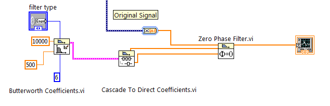
Butterworth filter without phase shift
Hello
I would like to design a 6 without a phase shift of order butterworth filter on my signal. A cutoff frequency of 500 Hz was chosen with a sampling rate of 10K Hz
Solved! Thank you ADE77
-
If the butterworth filter available in LabVIEW FPGA is cascade, can I get a higher order filter?
I need a 10th order filter lowpass butterworth with cut-off frequency 5 kHz. Can I build by 4th cascading of 2 order butterworth filters and 1 2nd order available in LabVIEW FPGA each filter in butterworth with cut-off frequency 5 kHz?
This will increase the amount that your data will be filtered but will not increase the order in the Manor that you think. If you cascade two 2 4th order filters and compare that results to a filter of order 8, the resulting field filter cascading bode would look more like a 6,5e order filter.
Logan H
-
. VI filtering IIR and response: response of Butterworth filter size depends on sampling rate - why?
Hi people,
I'm not an expert in the design of the filter, only a person in applying them, so please can someone help me with an explanation?
I need to filter signals very infrequent using a buttherwoth filter 2. or 3. order of the bandpass 0.1 to 10 Hz.
Very relevant amplitudes are BELOW 1 Hz, often less than 0.5 Hz, but there is as well the amplitudes beyond 5 Hz to observe.
It's fixed and prescribed for the application.
However, the sampling rate of the measuring system is not prescribed. It may be between say between 30 and 2000 Hz. Depends on the question of whether the same set of data is used for analysis of the higher up to 1000 Hz frequencies on the same measure or this is not done by the user and he chooses a lower sampling rate to reduce the size of files, especially when measuring for longer periods of several weeks.
To compare the response amplitude of 2nd and 3rd order filter, I used the example of IIR filtering .vi and response:
I was very surprised when I found that the response of greatness is considerably influenced by the SAMPLING RATE I say the signal generator in this example vi.
Can you please tell me why - and especially why the filter of order 3 will be worse for the parts of low frequency below 1 Hz signal. Told me of people experienced with filters that the 3rd oder will less distort the amplitudes which does nothing for my the frequencies below 1 Hz.
In the attached png you see 4 screenshots for 2 or 3 command and sampling rate of 300 or 1000 Hz to show you the answers of variable magnitude without opening labview.
THANK YOU very much for your ANSWERS!
Chris
Hello Cameron and thanks for my lenses of compensation.
I can now proudly present the solution of my problem.
It seems to be purely a problem of the visualistion information filters through the cluster of the scale.
After looking in the front panel of the IIR, I suddenly noticed that the "df" of the pole size is changing with the Fs of the input signal.
For a Fs to 30 Hz, the "df" is 0.03 Hz so you see the curve of the filter with more points, see png.
For a Fs 300 Hz "df" is 0.3 Hz, so the curve is larger with only 3 points between 0 and 1 Hz.
For a 1 kHz Fs the df is 0,976 Hz, so there is no point in the graph between 0 and 1 Hz.
It's strange that for constant Fs, df of this cluster NOT reduced with the increase in the number of samples, as it does in an FFT.
However, I hope now the filter used now for the curves obtained with the proposed Lynn way and the response of greatness from the filter information fit together.
Thank you for your support.
Merry Christmas and a happy new year to all.
Chris
-
Filter the data to WAV butterworth - problem
Hello!!
I have LabVIEW 2013
I m new in matlab and I have the following problem:
I want to filter voice and data to WAV file with block Butterworth Filter.vi. I don't know how to load the signal with his reading file Simple.vi, I know how to get the info on file with the Info.vi file, and I know that I can display data of waveform with waveform chart/graph. But I do not know how to properly set up butterworth filter in my diet, or better said how to properly bring data on this subject. When I m try to display data filtered with waveform graph I get only flat line.
I already checked OR examples (IIR Filter Design, IIR filter using option Specs, IIF assigned and response, IIR filter design). But after that, I felt even more stupid and lost.
In fact, depends on number of channels (mono/stereo) - should I separate?
Do I have to use a loop?
Second question - how many changes I have to do when I want to have a filtering in real time with filter.vi to butterworth (for example - to obtain data from the microphone)
Thank you very much!
Hi TOM 5 times.
you set a low pass of the 1st order, so he dampens high frequencies with only 20 dB/decade. It will NOT erase anything greater than 10 Hz, it will be just wet it!
You must use an order higher for your low-pass filter to effectively cancel higher frequencies!
-
Butterworth on Labview 8.6 FPGA filter problem
Hello
I was testing the filters of reconfigurable low-pass butterworth on FPGA found from the Finder of example (using Reconfigurable Butterworth filter - R - series.lvproj). This VI generates a sinusoidal signal and passes through a filter of Butterworth. When I put the filter low pass frequency to a low value (~ 2 Hz) and generate a sinusoidal signal of 0.5 Hz filttered out is not so much more (see figure). The filter is 2nd order, so this is a characteristic of the filter? And what do I do if I want a taste of high-frequency and use a low cutoff value?
v: * {behavior:url(#default#VML) ;}
O'Bryan: * {behavior:url(#default#VML) ;}
w\: * {behavior:url(#default#VML) ;}
. Shape {behavior:url(#default#VML) ;}Normal
0fake
fake
fakeMicrosoftInternetExplorer4
/ * Style definitions * /.
p.MsoNormal, li. MsoNormal, div. MsoNormal
{"mso-style-parent:" ";"}
margin: 0 cm;
margin-bottom: .0001pt;
MSO-pagination: widow-orphan;
font-size: 12.0pt;
do-family: "Times New Roman";
mso-fareast-font-family: 'Times New Roman' ;}
@page Section1
{size: 612.0pt 792.0pt;}
margin: 72.0pt 89.85pt 72.0pt 89.85pt.
MSO-header-margin: 35.45pt.
MSO-footer-margin: 35.45pt.
MSO-paper-source: 0 ;}
div. 1
{page: Section1 ;}}
--> I'm using Labview FPGA Module version 8.6 and PCI-7833R-map. LabVIEW 8.5, I remember that Butterworth filters, for above and below 2 kHz cutoff frequencies are actually different screws but on LV 8.6 they seem the same./ * Style definitions * /.
table. MsoNormalTable
{mso-style-name: "Table Normal";}
MSO-knew-rowband-size: 0;
MSO-knew-colband-size: 0;
MSO-style - noshow:yes;
"mso-style-parent:" ";" "
MSO-padding-alt: 0 cm 0 cm 5.4pt 5.4pt;
MSO-para-margin: 0 cm;
MSO-para-margin-bottom: .0001pt;
MSO-pagination: widow-orphan;
do-size: 10.0pt;
do-family: "Times New Roman";
MSO-ansi-language: #0400;
mso-fareast-language: #0400;
mso-bidi-language: #0400 ;}-Heikki
Hi Heikki,
The reconfigurable version (IE, with 'See the terminal configuration' checked) does not support the implementation of low-frequency modified. This is because we cannot change the filter architectures running. The nonreconfigurable version, however, must use the same implementation updated him you saw in LabVIEW 8.5 for the low cutoff frequencies, defined here as the frequencies less de.01 * sampling frequency.
Your example of 100 kech sampling rate. / s and 2 Hz cut-off is pretty extreme, even for the implementation changed. The usual technique for situations like this must be a smoothing downsampling at a rate that is better suited to the break you need. Rational resampling of the FPGA Math palette & analysis is designed for this purpose.
Kind regards
Jim
-
CAN´t set up a low-pass filter properly
Hello everyone,
First of all, sorry for my bad English!
Before asking this question, I ve tried to seek answers in the forum and couldn t find a useful for my case.
I m new to LabView and I m test for the analysis of the signals. I m using an Agilent signal generator and a NI USB 4431 to acquire the signal.
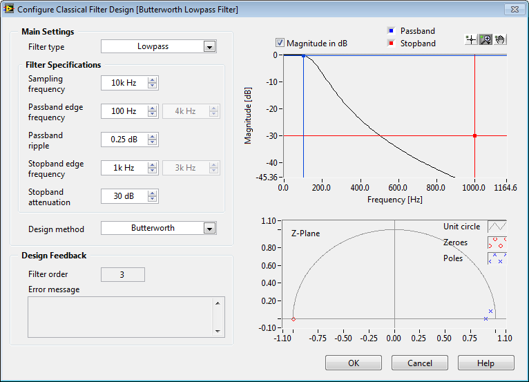
OK, here´s my problem. I can´t use of a Butterworth or a Chebyshev filter (or any type) to create a low-pass filter filter. I Don t know if I didn t understand it s parameters correctly or if I m set something wrong. When I use the ExpressVI filter, I get the result I want to, but when I use the function of Butterworth, it doesn´t work.
Can someone help me please?
I m sending the project I ve designed, so that you guys can see what I ve done.
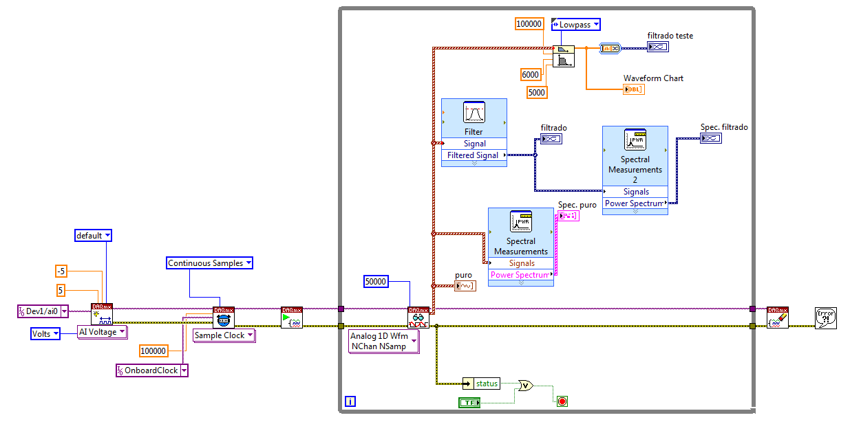
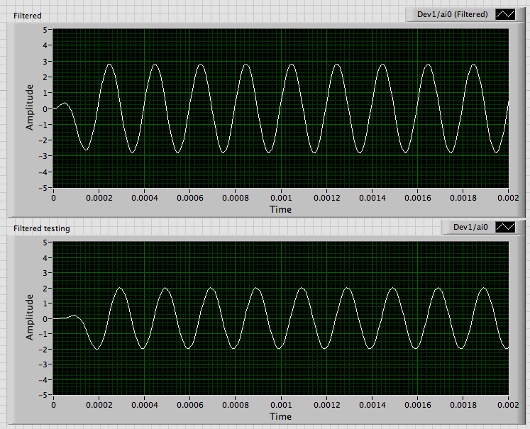
Here some explanations: the "puro" labeled graph is the pure I m signal generation.
The labeled graph "Spec. PURO"is the power spectrum of the signal current
The graph "filtrado" is the signal after going through a low pass filter in the express VI (which works fine) and the graphic "filtrado Spec" is the power of it s spectrum.
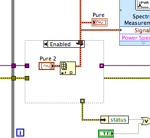
In the upper part of the loop is the function of Butterworth filter. I ve wired the pure data to its input signal and expect one out everything as the express VI creates, but he's not even conspire anything in the chart.
The windowed FIR filter VI generates the error-20023, which constitutes a violation of Nyquist. Because this VI returns only an error code and not the cluster of standard error, you must connect explicitly an indicator or manipulation to the error output.
The cause is that you have the frequency to zero. OR use a somewhat confusing nomenclature for the inputs of the filter frequency screw these detailed help says:
high cut-off frequency: fh is the high frequency in Hz. The default value is 0.45 Hz. The VI ignores this parameter when the type of filter (low pass) 0 or 1 (high-pass). When the filter type is 2 (bandpass) or 3 (Bandstop), high cut-off frequency: fh must be superior to low cut-off frequency: fl and respect theNyquist criterion.
Thus, for the high pass filters and both low-pass cut-off frequency is the value wired to low cut-off frequency: fl. I regularly get this error. When I get strange results, I read the help and fix it. As soon as I wired 5000 to fl, the output looks like this:
The differences in amplitude and transitory initial are likely due to different specifications of filter.
The way I start it is to convert the flag to a Pure control, do default to the current value, and then put all the DAQmx screws in schema structures disable. I have disable placing the pure control (or a copy of it) in a case to permit the schema structure which has the DAQmx Read. Since you have only one data channel I added the Index table to get a unique waveform of the table. Then all the code signal analysis works.
Lynn
-
Hi all
I was hoping that someone can point me in the right direction, because I've been searching the net and banging my head against the wall.
I want to filter the data, but eliminate the phase. Data are data from the simple will be stored in a table for post-processing. Is NOT in real time (making zero phase in real time is not possible, because we need to look to the future). I'm looking to use this:
http://zone.NI.com/reference/en-XX/help/372636F-01/mstudiowebhelp/HTML/92d15f99/
and also if we look at the IirFilterBase class, there is the above method of zerophaseFiltering that we can use:
http://zone.NI.com/reference/en-XX/help/372636F-01/mstudiowebhelp/HTML/bbfa383/
When I have trouble, is to know how to write the code to call the class and method in c#. I followed the example of code to tell a more traditional filter (such as butterworth etc.), and I am successfully using those... so nothing new to c# or programming to all...
Any who have an example or point me in the right direction on how I can use these features?
Is "IirFilterBase" common to all other filters, and we just need to pass the correct parameters for filtering done with zero Phase? In MATLAB, there is a function of simple 'filtfilt' to have done that, but for the life of me, I can't figure out how to have my filtered data, but eliminate angles of phase in with measurement of the Studio. I use MS 2012.
Thanks in advance for any help! Trully appreciate it!
Thank you for your answer!
I guess that I won't be able to use then. I'll try to take a more traditional approach as described here:
http://www.dspguide.com/CH19/4.htm
Filter toward the front, then on the other hand and then combine the result. I can easily implement what an IIR butterworth filter, and given that my data is stored (non-real time), should be simple to implement.
Will have to test this...
Thanks again for your time... enjoy it!
-
How to design a digital filter dump given in dB/Octave
I am designing a filter to DFD based on the attached image 'filter criteria. I think it's the prescription given by this image, the filter should be somewhere between two possible filters "border". I have convinced myself that the attached filter does not fit this criterion.
My thought is now that this criterion could be completed by a butterworth filter, as shown, but with the frequency of edge stopband at 250 Hz instead of 100 Hz, or an elliptic filter with a frequency of 100 Hz and the frequency of edge stopband at 1066 Hz edge of bandwidth, or any filter that is between the two.
I'm looking for details on how to enter the DFD toolkit directly given design criteria, so to know if there is a way to capture the attenuation in dB/Octave, or if my alternative interpretation of this roll-off can be used to design a filter as shown.
Any help is, of course, appreciated.
Thank you
Justin
Hello
It seems that you were using the stopband point as your fN instead of turning it off at the corner of the - 30 dB line and - line 9 dB/Octave.
If you do this, as well as use the 100 Hz points like the edge of your bandwidth, you should find that you can get a nice butterworth filter that is inside your notebook loads. For reference, here's something needs I came what looks like, it adapts to your needs:
-
Hello
I want to apply butterworth filter of 3rd order in FPGA. It must be possible to change the type (HP, LP, BP, BS) and run (cuttof freq) settings in FPGA. I found it's butterwort VI in FPGA Palette, but it is not possible to change the type of my host during the race.
I would like to ask what are the other options to implement the 3rd order butterworth in FPGA?
Now, my idea is to use the Digital filter design toolkit in reception get coef. Depending on settings and implement the polynom filters multiply and add the block in the FPGA. But I'm not sure about this...
Hello
You must modify the constant "low pass" level lowest control. See attached picture - I selected the constant in question.
Hope this helps
Maybe you are looking for
-
HelloMy %APPDATA%\microsoft\windows\sendto file specifies the id of the accident report is:Crash ID: bp-33827730-989e-4aeb-99c5-79b652151003 Basically, my Firefox and Internet Explorer crash at startup. I know that it is certainly linked to a virus I
-
Do not write satellite A60-672 DVD-R/RW
Hello can someone help me I just receive a satellite A60-672 when I try to write a dvd that he will not write one that I tried an audio drive, he writes very well on that told me that he will write on DVDs, the writer is a pioneer dvd - rw hard-k13a
-
Satellite A200-19 decies is strong enough - cooler runs constantly
Hello Last week, I have a Toshiba Satellite A200-19 decies. The laptop is very strong in my opinion. A chiller is running constantly and the other runs it sometimes. Or this noisy thing isn't a cooler? Please help me and sorry for my bad English. I'm
-
Revealing of objects in front of the Panel
Hey, I was in the middle of my program in labview to coding when I realized that I know nothing on the front panel. I am trying to show two graphs when I record a new audio file and then have those who disappear and show two different. I work with pr
-
How to disable the pop-up blocker?
I am trying to disable the blocker, adding a new site to the safe place, but I have no results. He tells me that the pop up blocker is on, but I want to help button and off, its tells me the same thing.