Calculation of derivative of clock for the NI 9234 module
Hello! I am relatively new to the use of material OR (and DAQ hardware in general), so this is probably going to be a really basic question.
We plan to use two 9181 chassis cDAQ with two modules NI 9234 sample data on 8 physical channels simultaneously at a rate of 25600Hz. As we use the 9181 chassis we cannot material synchronization as described in this topic:
«CDAQ-9181 will be out of the question because, as you said, it does not accessible PFI lines from the outside and you can not use a digital module for synchronization in a carrier case, because who was going to occupy the only available unit.»
We need the synchronization between the channels to be accurate to ±100ms. According to the http://www.ni.com/pdf/manuals/374238c.pdfspecifications, the time base internal master (fM) has a frequency of 13,1072 MHz and an accuracy of ± 50 ppm. I'm trying to calculate the maximum amount of the derivative of the clock, more than 1 hour. The selected sampling rate influence the result?
I think what meant Henrik was to connect the same signal to a channel on each of the two modules. This way, you have two digital versions of the same signal with each being scanned by a different clock. As long as it has the signal which can be identified in the worst case timing difference, you can determine that the sample [e] in a set of data has occurred at the same time (period a sample) as sample [k] with the other set of data. Then, you apply this synchronization relationship to all other channels in the two modules.
Strictly speaking, it is the difference in frequency between the two clocks, no drift. Data sheet specifies the precision of freqeuncy as +/-50 ppm, but specifies no drift at all. Drift has usually two components - temperature and duration. Drift in temperature is specified as ppm/degree, while the drift of time (also known as aging) can be specified as ppm per year. The two drift coefficients are usually smaller than the specification of the accuacy. It is not unlikely that the precision specification can include effects of drift.
If clocks drift significantly for the duration of your run, you may need to correct calendar several places in the data set. If the two chassis are physically close, any change in temperature will probably be very similar for both devices and aging is generally not relevant for periods of one hour. I suspect that the initial frequency differences are the only things that will be of interest to you. If a few ppm drift issues, let the two devices to heat for an hour before starting the test. This should be enough to stabilize temperatures.
Lynn
Tags: NI Hardware
Similar Questions
-
How to set the clock for the hours, minutes, and seconds with Windows XP
How to set the clock for the hours, minutes, and seconds with Windows XP
I don't know of your question. If you ask how to show the clock in the tray system with hours, minutes and seconds, then download & run "Tclock Light". Windows will not natively display the seconds.
TClock Light: <> http://homepage1.nifty.com/kazubon/tclocklight/index.html >
HTH,
JW -
Possible to use the main clock FPGA as a basic Source of time for the NI 9234?
Hello
I am running a NI 9234, and NI 9222 module on a cRIO-9114 chassis with a real-time 9022 controller, data acquisition on the 8 channels on the full sample rate, using the FPGA.
My problem is the synchronization of the data, where the NI9234 is usually a late acquisition, compared to the NI9222. I tried manually delay the NI9222 to take the first samples, but so far without success.
To solve this problem and also to ensure a rate of data more comparable on both cards, I was wondering is it possible to create a Source of time Base master for the NI9234 WITH THE FPGA (opposite to import from another NI9234 or similar module)? The NI9222 I already provide with sampling of the impulses from the FPGA (as expected with this module).
Another issue would be the characteristics of the exact chronology of the two modules, including in terms of synchronization between the beginning of the acquisition and the first samples of data. I couldn't find any information about it...
Thank you in advance,
O Hoppe
Hello!
I've never heard of a possibility to use a time base FPGA with a module of Delta-Sigma.
But I think that the question should be what has not worked to delay the signal and how you did it. Have you read this article?
How can I compensate for delays of different group with the C Series Modules in LabVIEW FPGA?
http://digital.NI.com/public.nsf/allkb/74EB238E1BCADD528625735300681A7DCan you give a more detailed description of your trial to delay acquisitions? Can you provide a code example?
Best regards
Christoph
-
Serial numbers for the cRIO-9081 Module
Is there a way for the FPGA in the cRIO-9081 to read the serial number, date of calibration of the NOR-9201 module installed in the cRIO?
I want to get this information and send it to my Host.vi, because we have a duty to provide information instrument document during a series of tests.
Thank you
Paul
Use a property node of the module to read the number of series/VendorId... but the calibration date is not stored. (FPGA code example shows NI9205 data)
Here a Fifo of DMA target host is used to send the data to the controller of the CR...
-
How to add a dependency to the library for the java service modules?
Hello
I try to add Google gson jar as a dependency of the sample of chassis (/ chassisRackVSphere-service) and I'm facing some problems with the installation of osgi.
////////////////////////////////////////////////////////////////////////////////////////
Report of resolver:
A Package Import could not be resolved. Resolver error data < Import-Package: com.google.gson; version = "0.0.0" >. Caused by the constraint missing bundled < com.vmware.samples.chassisrackvsphereservice_1.0.0 >
constraint: Import-Package: com.google.gson; version = "0.0.0" >
at org.eclipse.virgo.kernel.install.pipeline.stage.resolve.internal.QuasiResolveStage.process(QuasiResolveStage.java:46)
at org.eclipse.virgo.kernel.install.pipeline.internal.StandardPipeline.doProcessGraph(StandardPipeline.java:62)
at org.eclipse.virgo.kernel.install.pipeline.internal.CompensatingPipeline.doProcessGraph(CompensatingPipeline.java:73)
at org.eclipse.virgo.kernel.install.pipeline.stage.AbstractPipelineStage.process(AbstractPipelineStage.java:41)
at org.eclipse.virgo.kernel.install.pipeline.internal.StandardPipeline.doProcessGraph(StandardPipeline.java:62)
at org.eclipse.virgo.kernel.install.pipeline.stage.AbstractPipelineStage.process(AbstractPipelineStage.java:41)
at org.eclipse.virgo.kernel.deployer.core.internal.PipelinedApplicationDeployer.driveInstallPipeline(PipelinedApplicationDeployer.java:359)
////////////////////////////////////////////////////////////////////////////////////////
Here are the things I did based on the addition of the gson - 2.2.4.jar to the list of libraries (which I'll use my service module).
1 added gson - 2.2.4.jar to chassisRackVSphere-service\lib
2. added gson - 2.2.4.jar to the list of libraries referenced in STS.
3. fixed the ANT build file to add this jar to the classpath
< target name = "java-compilation" depends = "clean" description = "do not select objective in-house." >
< javac includeantruntime = 'false' destdir = fork "${CLASSES}" = "true" debug = "on" >
< path src = "${basedir} / src/main/java" / >
<!-< path src = "${basedir} / src/test/java" / > for future test-> files
< classpath >
<! - remove this if you are not using the SDK with java - >
< pathelement path="${VSPHERE_SDK_HOME}/libs/vsphere-client-lib.jar"/ >
< pathelement path="lib/commons-logging-1.1.1.jar"/ >
< pathelement path="lib/gson-2.2.4.jar"/ >
< / classpath >
< / javac >
< / target >
4. fixed the manifest file to include the package gson
/////////////////////////////////////////////////////////////////////////////////////////
Import-Package: org.apache.commons.logging,.
com.google.Gson,
com VMware.vise.Data,
com VMware.vise.Data.Query,
com VMware.vise.Data.Uri,
com VMware.vise.vim.Data
/////////////////////////////////////////////////////////////////////////////////////////
I don't know what I'm missing. How can I add third-party libraries for the service module (in this case chassisRackVSphere-service)? Any help is appreciated.
Thank you
Shankar
You forgot a step described in the FAQ ""How to use 3rd party java libraries?', that is to make your available on the server gson library. " An excerpt from the FAQ:
Formatted as OSGI bundles libraries should be in a known location on the server:
- In development mode you can copy in Server/repository/usr, one of the default directories for the loading of libraries (you must restart the server).
- If the server is already running you can copy also in Server/Pick-up because the beams will be deployed hot (i.e. without having to restart, but this requires you to deploy your plugin after the library, see Note 2 below).
- Finally, you can keep in their current location and add a path in server/configuration/com.springsource.repository.properties.
- In production mode , that your plugin is installed as a plugin package, it is neither practical nor recommended to add libraries to server/Pick-up or Server/repository/usr on your production server. Instead you must include them in the directory plugins of your package and your .war and .jar packages. You will also need to list Bundle-SymbolicName of plugin libraries - package.xml.
-
Configuration of the basic Source of time to master for the 9234
I have several cDAQ modules I use to collect data. I use vi to Write can Express to save data to a file of PDM.
When you examine the recorded data files, the measured data from NI 9215 provide pleasant timestamps to match how the DAQmx task has been set up--delaying the sampling frequency of 1000 with a 1 ms in the While loop. However, although in the same vi - different tasks, but the same while loop - horodateurs of the NI 9234 do not correspond to the task of DAQmx implemented - sampling frequency of 1000 with a 1ms delay. After reading the material provided with the NI 9234, I found that maybe the machine clean master Timebase Source. There were documents that says he can be configured to be originally of Timebase of Master for the other modules:
Configuration of the basic Source of time of the master for the NI 9234 (Interface FPGA)
It is desirable to have the timestamps for data measured across all modules to match. We do not have the FPGA Module for LabVIEW. Is there a method in LabVIEW for all modules use the same master time base Source? I assumed that because all the data collection has place in the same while loop by using the time delay of 1 ms it was forced through the code. This hypothesis seems incorrect from my review of the PDM data files.
The NI 9204 provides a trigger only.
Software:
Windows 7
LabVIEW 2010 SP1
Material:
CDAQ-9174 chassis
Slot 1: NEITHER 9204
Slot 2: NEITHER 9215
Slot 3: NEITHER 9234
Slot 4; Vacuum
Hi MgDAQ,
An important concept to note is that the 9234 uses a delta-sigma converter and a clock of oversampling to read analog data. There is an inherent delay of entry due to analog and digital filtering built-in. Since the 9215 has a lower resolution there will be a lag the 9234 and 9215 finished. I've included some resources below:
What are the for the NI 9233, NI 9234, and NI 9237 valid sampling rates? : http://digital.ni.com/public.nsf/allkb/593CC07F76B1405A862570DE005F6836?OpenDocument
Synchronization of DSA, S and X series devices with a NEITHER-DAQmx single task series: http://digital.ni.com/public.nsf/websearch/78E44565FD87E7D686257108007F94F8?OpenDocument
Synchronization with NOR-DAQmx of acquiring dynamic signals (DSA) products:http://digital.ni.com/public.nsf/allkb/A133ED27DF9BCC5986256F2E004BA342?OpenDocument
Have you tried to put two modules in the same spot? Alternatively, you can export the sample clock 9234 and tasks installation separately.
Best,
CARISA
-
I recently bought a 7811R. I have a need to synchronize the external clocks (requires 3 in fact). How to set up external clocks for the 7811R in Labview FPGA modules.
Emax,
Unfortunately, not all FPGA target supports this feature. Currently, the R-series cards are not able to do. However, FlexRIO target supports using resources DIO as an external clock, including the following models: 7951R 7952R, 7953R and 7954R.
What components you try to synchronize in your application and how fast your clock do you have to go?
-
best practices for the evaluation of prerequisite logic GOLD
Greetings,
I think TS is not the basic features for the decision-making process (imp) for execution. All recommendations are welcomed and appreciated. Please find below the script.
I would like to perform some configuration steps (custom step types) to a signal generator based on the selected user 'Test '.
To make it simple for the signal generator Let's say, we have the following steps:
The Freq value | Define PWR lvl | Set the Modulation Type. Set the Modulation ON / OFF. Setting the output RF ON / OFF
For the selected user Tests say that we have Test (0) | B test (1) | C (2) to test (Test A & C requires Modulation, B does not work)
Here's my question:
I can't get the Freq VALUE | The VALUE PWR lvl | Value RF Power on / off to run installation of prerequisite for the evaluation of logic GOLD. (i.e. residents.) TestSelected == 0 | 1. 2)
Ditto for the Type of Modulation Set | The value of Modulation on / off (ie the inhabitants. TestSelected == 0 | 2)
Thanks in advance for any help provided.
Chazzzmd78
people of the country. TestSelected == 0 | 1. 2 would be at the local level. TestSelected is 3. You're doing a bitwise operation GOLD on numeric values, then the comparison.
You need
(the inhabitants. TestSelected == 0) | (the inhabitants. TestSelected == 1) | (the inhabitants. TestSelected is 3)
-
What are the data for the PXI-6552-invalid range
Hello
Let say, I put the voltage custom for the PXI-6552 module
2.4V - high level
0.6V - low level
Then, on canal0, I provide a signal of
sample
3V 0
1 3V
2 VOL. 2
3-0V
Thus, the sample 0.1 is high. Example 3 is Low.How sample 2? Please notify. Thanks in advance.
Hi Engwei,
Programmed tensions are the levels that you would have to exceed or down before a change of digital status is saved. This means that in your example, coming from a high level of 3V goes to 2V, the Analyzer signals would still record a strong logic. The deadband is actually a way to filter digital noise, common to the majority of the architecture of digital input.
Best regards
The Ilana Joshua
Applications Engineer OR -
Impossible to read 4 channels with the or 9234
Hey, I'm tasting 4 simultaneous channels to 51.2 kech / s rate for each channel with the NI 9234 module.
I use a callback function to read from the buffer.
I am accept to get to playback 4 channels of 51.2 k * 4 = 204.8 k s/s.
and I still recive data 51.2 kech / s.Need help, I don't know what's wrong with my code.
I enclose my hope of code it will help...
Thank you!

My installation information:
Material: NEITHER 9234
Version of Windows: XP
Language: Qt (C++)Hey simon27,
When you have installed DAQmx, did you also install text code support? There are several examples that should have installed with DAQmx which is very helpful in getting you started. "" "" "They can be found by going to your Start menu, then all programs" National Instruments "NOR-DAQ" NOR-DAQ "support textual Code ' ANSI C examples.
In case you do not installed the supported text based code, I have attached two examples which I think would be more useful to you. Try to run these examples and see if you get the same errors.
-Nathan H
-
Synchronize the FPGA clock for clock RT?
Hello
I use a sbRIO-9612. Data are acquired for several weeks, and the problem is that the clock of RT of derivatives. I found a technical document to synchronize the clock of RT with SNTP server:
http://digital.NI.com/public.nsf/allkb/F2B057C72B537EA2862572D100646D43?OpenDocument
But I do not find anything on the FPGA clock. My data are acquired by the FPGA, my question is: How can I synchronize my FPGA clock with my RT clock or the SNTP server? (this is probably a stupid question, but she clearly explains my problem) SbRIO is suitable for my needs? Should I waive any 'acquisition of FPGA based' and use a different hardware architecture to perform data acquisition synchronization?
Thanks in advance for any help.
Julien
Hi Julien,
Take a look at "RT masters FPGA synchronization Example.vi" on the FPGA Timekeeperpage. There's a Subvi, which uses a timed writing periodically present to the FPGA so that the FPGA can have a domain time synchronized with respect to RT if you have questions about this example, try to publish to category of Discussion of the project.
-Steve K
-
Is it possible to use the internal clock for meter tasks in the buffer?
Hello
Hardware: USB term mass 6251
Software: LabView 2011 SP1
I need to measure the angular lever position and speed of a carpet. For that I use two quadrature encoders. To accurately calculate the speed I use buffered from the measures of position using one of the available onboard counters. I understand that for this technique, I provide a sample for the meter clock. I wonder if it is possible to use the internal time base. Note that both of my counters are used so I can't generate a signal to clock with them.
I found two conflicting pages related to my problem:
1) http://digital.ni.com/public.nsf/allkb/EA7FFFEAFC3E1D85862572F700699530
2) http://digital.ni.com/public.nsf/allkb/775290A3121D1FFC862577140074D3B3
The first says that I can use the internal clock of 100 kHz, and the other says that I have an external clock.
Comments/solutions?
Javad
Hi Javad,
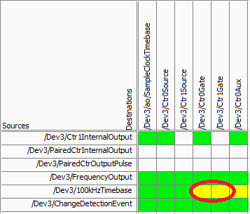
On your specific device, there is not a direct route from the time base of 100 kHz for the meter (according to the routing table of MAX):
Yellow cell indicates that a route is possible but there is not direct (the "gate" terminal is used as sample clock for counters of the M series). Mouse on the cell reveals yellow that make this route really requires the use of a counter (so it is not suitable for your application).
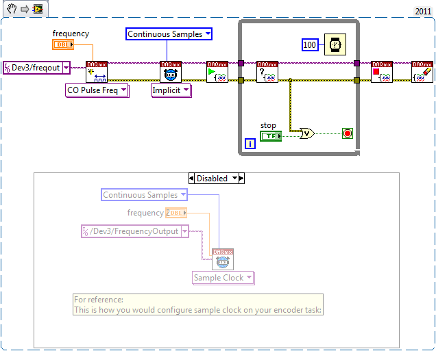
On the line above "100kHzTimebase" you will notice it is called 'FrequencyOutput', which does not have a direct route to the door. This would be the way to go if you want to route 100 kHz (or some other frequency) as your sample counter clock - you can set it up the same way to a standard meter output task:
The output frequency doesn't have that many features like a meter output, but it is able to generate a continuous stable frequency. There are only 32 different frequencies that can be generated using Freq Out on the 6251:
{10 MHz, 100 kHz} / {01:16}
Do not forget that the resolution of your measure of frequency by using this method will be equal to how many times you update the measure (hopefully, that makes sense). In other words, if at the end of all the 1 second, you take the total number of charges since the last second, you would have a 1 per second equal resolution change in the number. If you take the difference twice per second, you would end up with half the resolution. You will be sampling the account register fairly quickly, but you will need only to do the calculation of the frequency after that all N samples in order to obtain a significant number.
Another method that will certainly give a higher resolution in less time at typical speeds of coders is to set up a measurement of the frequency (the counter will count the internal 80 MHz base time period your external signal and the pilot calculates the frequency based on the result). This method uses only a single entry - so you can just feed the 'A' your encoder quadrature signal (the method will not work if you are interested in absolute position or direction). Without using signals A and B together, you will be susceptible to noise (which is common to have a quadrature encoder) that you want to delete (perhaps by setting up a digital filter). Finally, you want to set a reasonable timeout on your reader calls (which will be blocked until a period of your external signal occurs), and the error-200284 handle simply report "0Hz" to make sure that your program is still sensitive even without an external signal present.
Best regards
-
I want to integrate the ANSI C sample program ReadDigPort - ExtClk.c in my own big package.
I want to use the internal clock of the BNC NI USB-6259 (.. 80 kHz 120 kHz).
In the document:
High speed M: Series Multifunction DAQ for USB - 16-bit, up to 1.25 MECH built-in BNC connectivity. / s,.
is written:
Or sample DI source clock: Any PFI, RTSI, HAVE sample or convert clock, AO, Ctr n out internal and many other signals sample clock
The digital subsystem doesn't have its own dedicated internal synchronization engine. Therefore, a sample clock must be provided another subsystem on the device or from an external source.How can I use internal clock case OR USB - 6259 BNC for the acquisition of digital data in my own big software?
With what other subsystem on the device can generate a source of the clock? How?It is possible to set a clock on an internal counter (for example ' Dev1/ctr0"):
Creates channels to generate digital impulses that define the freq and dutyCycle and adds the channel of the task that you specify with taskHandle.
DAQmxCreateCOPulseChanFreq (taskHandle, "Dev1/ctr0" units, clockName, idleState,
initialDelay, freq, the duty cycle); worksBut it is not possible to drive this internal clock to a terminal (for example "/ PFI0/Dev1"):
DAQmxErrChk (DAQmxCreateCOPulseChanFreq (taskHandle, "/ PFI0/Dev1", clockName, units, idleState, '))
initialDelay, freq, the duty cycle); does not work: error DAQmx: measurements: type I/O of the physical channel does not match the type of I/O required for the virtual channel you create. Name of the physical channel: PFI0. Name of the virtual channel: clockThe sample clock source can be derived from an external terminal (for example "/ PFI0/Dev1"):
Sets the source of the sample clock, the sample clock rate and the number of samples to acquire or generate.
DAQmxCfgSampClkTiming (taskHandle, "/ PFI0/Dev1", maximumExpectedSamplingRate, DAQmx_Val_Rising, ")
DAQmx_Val_ContSamps, bufferSize); works. Acquire or generate samples until you stop the taskBut it is not possible to derive the internal counter of the clock (for example ' Dev1/ctr0"):
DAQmxCfgSampClkTiming (taskHandle, "Dev1/ctr0", maximumExpectedSamplingRate, DAQmx_Val_Rising,
DAQmx_Val_ContSamps, bufferSize); does not work. Error: Acquire or generate samples until you stop the task: make sure that the name of the terminal is valid for the specified device. See Measurement & Automation explore valid names of terminals. Property: Property of DAQmx_SampClk_Src: DAQmx_SampClk_ActiveEdgeSource device: Terminal Source Dev1: Dev1/ctr0Hi datafriend,
using what it says is correct:
Or sample DI source clock: Any PFI, RTSI, HAVE sample or convert clock, AO, Ctr n out internal and many other signals sample clock
The digital subsystem doesn't have its own dedicated internal synchronization engine. Therefore, a sample clock must be provided another subsystem on the device or from an external source.This means that if you do not use an external signal as clock you can use the sample clock to HAVE it on board or at the output of the internal counter.
There are also 2 ANSI C examples in this regard:
http://zone.NI.com/DevZone/CDA/EPD/p/ID/4485
http://zone.NI.com/DevZone/CDA/EPD/p/ID/4488
So in both cases you have to use a fictitious task you need only for the generation of the internal clock (HAVE or CTR)
-
HP 40GS stuck on the hourglass for the calculation of certain integrals
So I used my calculator HP40GS for awhile, and I've never had problems with it.
Recently, when reviewing for the examination of calculation AP, I noticed that the calculator could not do some integrals. Because I already went through the lesson using the graphing calculator calculators and integrals without problem using my computer, I don't think that there is nothing special about this one.
One of the integrals in question is 3 * e ^(-x/2) * sin (2 x) on the interval [0,2].
I tried to make the home screen capture (in the mode of operation):
∫ (0,2,ABS (3rd ^(-x/2) * sin (2 x)), x)
The calculator has been blocked at least five minutes on the same screen with the little hourglass until I pressed on 'on' to force her to leave.
Also, I tried to do this in CASE mode, using the manual view. This also does not work.
Other calculators in the classroom (TI-83) did the integral almost immediately.
My memory is not yet close to being complete.
Is there something I could do or check to solve the problem? Other integrals seem to be more or less fine.
Thank you!
When you do digital integrals, some of them may take some time. On the 40gs and many other units of HP, the accuracy of the correction is what distinguishes the accuracy of assessment. Try to set the precision of DIFFICULTY 4 in the homescreen of modes and re-evaluate. I suspect that he will return very quickly. That should mean "exact to 4 decimal places.
You can also try to do exactly in the CASE and then to assess the result. In many cases, it may be faster.
-
App for the time and payroll sheet calculations
My daughter in hospitality makes work so much split and travel on a Saturday and Sunday. I am looking for an application that we can punch in his hours for the week and be able to do the calculation of salary based on the appropriate hourly rate so that we can keep control of when it is paid as it's done correctly. Essentially, I'm lookin for an app connects timesheet information to the payroll data. Such an application exists and if so can anyone recommend one? Happy to pay for an if need be.
Hello alissah6,
Numbers from Apple is what I would recommend as far as doing calculations with a simple formula. You can learn more about this here.
The application costs $14.99, however it is packed and has more than 30 models - not to mention, you can also create your own if necessary.
I would check it out certainly if I'm looking for a few terms related to pay calculation in the App Store.
Thank you
James.
Maybe you are looking for
-
Numbers, what happened to the "get info" command to the document properties?
I was frustrated by this month. Where the order read to find the document? Or if Apple has changed the Download the script for information where is the command? This frustration is usually when you use a portable office/computer version, but I gues
-
Why the logos of the site Web also have names?
In the toolbar, I was happy with a few logos. Recently, the names of the sites Web appeared and I can't figure how to get rid of them. I want fair logos on the toolbar.
-
Web site looks different without "www" is entered in the address bar.
Hello, I just created a web site, www.danwoodard.com. When I type in "www.danwoodard.com" everything seems as it should. However, if I omit the "www" and enter only "danwoodard.com" the site is much larger than it should be. This does not happen with
-
Satellite C660-1LD: how to recover and return to the factory settings
Hi guys,. I suffer with any problem on any website a few linked words and when I click on it, an ad. opening of site Web which is a little virus I think and the laptop runs very slowly I decided to restart the laptop of the t and return to the factor
-
everyone put updated for Java update 8 73
Someone has updated updated Java 8 73. It wants to install a "helper" on the computer and I'm not comfortable with that. I still have a pop-up that gets in the way of a Java update earlier that I can't get rid of so I just not sure if the "helper" i