Calibration of NOR-9234
Hi all
We received one of these hardware DAQ (NOR-9234) and cDAQ-9174 chassis and the waters so to speak check if we want to expand our capabilities.
I'm running Measurement & Automation Explorer 5.1, and by the NI 9234 installed manual calibration DAQmx 9.5.1.
I did the magority of exploring how to calibrate it and everything communicates well, but am stuck with a couple or two clarifying questions.
1. the manual shouts using the chassis NOR cDAQ-9178 with 9234 in slot 8 and all the other empty. The cDAQ-9174 usable instead, so far, all the prelim-tests I did not show any problems?
2. that reference manual calibration page 7 step 9 according to the criterion of Phase-matching, he shouts using the extract «only your Infomration.VI» Is a VI that is available if you have installed a version of LabView, or is this something (I was not able to know how to do) that can be run in the MAX/DAQmx software? Currently, we don't have labView, but will be willing to make the purchase for this and others if I can get the basic understanding of what we need to do.
3. If the verification procedures run in the specifications, the 9234 needs uploaded/updated info to update, as the most recent calibration due date or something?
Thanks for any help in advance.
Stan
Hi StanL,
Well using slot 8 a OR cDAQ-9178 would be ideal, you should be fine using the 4 slot of the NOR cDAQ-9174. From what I can tell, the manual recommends using the last location because it is farthest from the controller, giving you the best all electric isolation or thermal noise.
Best,
Tags: NI Hardware
Similar Questions
-
Sync module NI 9205 with NOR-9234
Hello
I have a cDAQ-9178 chassis with 4 x accelerometers IEPE PCB 16 absorbent of NOR-9234 (DSA). I have a NOR-9205 I intend to use to acquire the power of 4 problems. The NI - 9234 s are synchronized through their extensions in a single task. I would add the NOR-9205 to the chassis and synchronize it with the NOR - 9234 s. I have the following questions:
1. Calendar synchronization
How to properly START and the NOR-9205 CLOCK synchronization with the NOR - 9234 s? PXI I export the master St DSA. WHICH device (OR-9234 or NOR-9205) should export WHICH signals to WHOM?
2. even or parallel task
Since I produce a TDMS file in its task of NOR - 9234, it would be nice if I could simply to ADD the OR-9205 to this task to develop this unique TDMS with extra 4 channels of the NOR-9205 file. Is this possible?
Thanks in advance,
Hi golubovski,
> Are you saying my task of canal expansion can fire them OR - s and NEITHER-9205 9234 with its 32 channels of multuplexed HAVE? How to recognize which modules can be combined in this way convinient?
Yes. With the cDAQ-9178, any set of AI modules can be included in the same task and in most cases that apply to the AO and DIO as well, but you cannot mix a, AO and DIO in the same spot. The NOR cDAQ-917 x manual goes into more details on what combinations of modules, the types of channels and the tasks are possible.
> I am aware since I worked so far with the PXI - 4472 DSAS. How well can correlate between the NI 9234 - and the NI9205?
Well, I wanted to make sure that you did not know that it is something that you'll probably need to take into account. On the top of my head, I don't know the answer to this question.
> As far as I know, in which case I use dummy DAQ with the NOR - 9234 to offset 40 clock cycles I guess I'll need to separate the tasks - how to integrate viewers into a single stream of TDMS?
If you use two separate tasks and you are using the built-in support of DAQmx for TDMS logging, then you will get flow TDMS separated for each task. Note that a dummy read will still record to the PDM file, then maybe it will not work in your case.
If you use the TDMS API to write to the PDM file, you can do the preliminary processing of data before it is written in a single stream, but there is some trade-off between ease of use and efficiency: either you write data point floating in the file (easier but less effective), or you have to deal with scaling (most effective raw data (, but harder to do).
Another approach is to put all the modules in the same task and compensate for the delay of the filter after reading the data from the PDM file.
> Also, for fixed 3.2 µs I have to calculate how many cycles given the actual sampling frequency or is there another method?
If you filter delay compensation by removing a whole number of data samples, then Yes. However, there are other methods of data processing that can compensate for a number that is not part of the sample clock periods. I don't have a recommendation, but maybe someone else does?
Brad
-
VST: entered password for calibration of VI
Where do we get the password, which is a string input required for the screw for the VST calbration?
The default password of calibration is 'NOR '.
-
Acquisition of vibration with the NI USB-9234 using the NIDaqMxBase library
I have a NI USB-9162 linked to a NOR-9234 properly configured and installed under OpenSUSE 11.3. It's the output of ldaq:
>lsdaq
--------------------------------
Detecting National Instruments DAQ Devices
Found the following DAQ Devices:
NI USB-9234: "Dev1"    (USB0::0x3923::0x72B5::0164852A::RAW)
--------------------------------
I'm developing a simple application to acquire the values of vibration of a project connected with an accelerometer.
We start from the example of acquireNScans - AnlgStart.c of NIDaqMxBase 3.4.5 documentation.Unfortunately, the program fails and generates the following error:
"DAQmxBase Error -200428: Value passed to the Task/Channels In control is invalid."
Then I realize that the NI9234 doesn't support analog and digital triggers so I have decided to try with the acquire1Scan.c (a scan without triggering):
int main(int argc, char *argv[])
{
    // Task parameters
    int32       error = 0;
    TaskHandle  taskHandle = 0;
    char        errBuff[2048]={'\0'};

    // Channel parameters
    char        chan[] = "Dev1/ai0";
    float64     min = -10.0;
    float64     max = 10.0;

    // Timing parameters
    uInt64      samplesPerChan = 1;

    // Data read parameters
    float64     data;
    int32       pointsToRead = 1;
    int32       pointsRead;
    float64     timeout = 10.0;

    DAQmxErrChk (DAQmxBaseCreateTask("",&taskHandle));
    DAQmxErrChk (DAQmxBaseCreateAIVoltageChan(taskHandle,chan,"",DAQmx_Val_Cfg_Default,min,max,DAQmx_Val_Volts,NULL));
    DAQmxErrChk (DAQmxBaseStartTask(taskHandle));
    DAQmxErrChk (DAQmxBaseReadAnalogF64(taskHandle,pointsToRead,timeout,DAQmx_Val_GroupByChannel,&data,samplesPerChan,&pointsRead,NULL));

printf ("Acquired reading: %f\n", data);
Also this program fails and gives this error:
DAQmxBase Error -200077:
Requested value is not a supported value for this property. (Timing Mode) How can I get at least a single data value of the accelerometer of the device using the NIDaqMxBase API?
Hi giaulo,
The examples that you have tried to run are not compatible with your device.
The 9234 does not support analog triggering, so examples of "acquireNScans" - AnlgStart.c do not work.
He is also unable to make an acquisition of single point because is based on the architecture of delta-sigma ADC. Here is a knowledge base article explaining the limitation:
KB 4SU94SH7: DSA Hardware Support a Point Acquisition?
This is the reason why the "acquire1Scan.c" does not work.
You will need run one example making an acquisition in the buffer. "acquireNScans.c" would be a good to watch. Be aware of all these examples, the default is +/-10V input range. The 9234 can only input +/-5V, so it will take a few changes. Also as you try to read an accelerometer, IEPE excitement is probably necessary. I've attached an example which is based on the example of "contAcquireNChan.c" that defines the range and allows the excitement for the device correctly.
-
Hello
I have a compact rio, which has a 4 way frame this chassis is the three modules of ni9234, they are related using FPGAs for application in real time, then using shared variables in the low-speed loop associated with a slave modbus to communicate with the domain controllers, the nor 9234 accelerometers linked to them with option ac coupled iepe on c modules , my problem is the real-time application seems to work well even when power loss occurs it restarts without problem and the fpga written hard disk portable bin files very well, but without an accelerometer connected I get readings of low noise as soon as I connect an accelerometer to one of the outputs 10 it just goes to a fixed number (0.03125) as soon as you unplug it again He returned to readout noise, I ran a scan on the modules and get only a spike when I connect or disconnect the accelerometer, I tested voltage at the pins on the module and I get 22 volts CC which makes it more likely that the material is not the problem, but software is perhaps the cause to hang up, I join the project and files for your perusal. I also realized a new project which, in mode directly linked scan has the module entry in the shared variable and the scenerio even once again. Help would be appretiated.
Thank you very much
Jason
Whren using waveform with the 9234 acquisition, we recommend the following FPGA and RT model.
http://sine.NI.com/NIPs/CDs/view/p/lang/en/NID/209114
It can be extended as a datalogger with:
http://zone.NI.com/DevZone/CDA/EPD/p/ID/6388
or using shared variables combined with the analytical engine
http://zone.NI.com/DevZone/CDA/tut/p/ID/9851
The FPGA in all this, as well as the framework of RT have used successfully by 1000s of users. I recommend giving these a try.
-
To input analog shutdown when the analog output is completed and synchronization
Hello
I'm trying to get my LabVIEW program to send analog output to a computer and read acceleration using the cDAQ-9184. Chassis output that I use is the NI 9263 and the chassis of entry is the NI 9234. I generate a signal of white noise using LabVIEW Express signal generator.
The first problem I have is the synchronization. I had an old VI that has begun to measure the acceleration just about a second after the entry has been given to the machine. I used the LabVIEW tutorial on how to sync the analog input and output, only to discover that it does not work with two different hunts. Then I found another tutorial that shows how to synchronize different frames between them.
The second problem is the cessation of the LabVIEW program. What I want to do is to generate the signal and then simultaneously send and read the input and output analog, respectively. It is because I don't want a phase difference or any shorter signal for a direct comparison. But as soon as the signal is sent to the machine, I want the entry to stop analog playback and then then the LabVIEW program must stop. I want to be able to choose any length of signal to be generated and stop as soon as the entire duration of the signal has been sent to the machine.
I tried 'DAQmx stop', "DAQmx Timer" and 'DAQmx's task made?' and none of them have worked for me. It is also my first time on a forum posting, so I hope I gave enough information. I enclose my VI as well. The VI shows I read an entry for the analog input voltage, but I am only using this to try to get to the work programme.
I'd appreciate any help I could get.
Thanks in advance
Peter
Hi Peter,.
I have some recommendations for you that I think you will get closer to your solution. First of all, I assumed you meant that you had 1 chassis (cDAQ-9184) who had two modules in it (NOR-9263 and NOR-9234). My next steps are based on this assumption, so if it's wrong, please let me know.
For your first question about the synchronization, the code you provided is very close to what you need. You need to do, however, implement architecture master/slave for startup tasks DAQmx functions. To do this, you can add another frame to the flat sequence structure and put the master start task (input voltage) after the start slave (output voltage) task.
To manage your second question and that the program ends at the point where you, the first step is to get rid of all the logic that you use with the local variable of length of time. Rather than use this logic, just wire the node "task performed?" of "is task performed?" operate to stop the loop. This will cause your loop to stop as soon as the signal is sent to the machine.
I have some other recommendations for you that will increase the performance of your program:
(1) rather than writing on file inside the last loop, you can use the DAQmx Configure Logging (PDM) .vi. You will place this VI between DAQmx Timing.vi and DAQmx Start Task.vi to the task of the analog input voltage.
(2) after the last while loop, you want to stop the task and analog outputs as well with another DAQmx stop Task.vi.
(3) rather than using a local variable for the entrance of displacement and wiring it in the DAQmx Write.vi, you can wire directly from the output waveform of the wave to build function node.
That should help you get started in the synchronization of these tasks.
-Alex C.
Technical sales engineer
National Instruments
-
Is it possible to display my measurements on my iPad 3?
is it possible to display my measurements on my iPad3?
I'm having cDAQ 9191 and NOR-9234, I'd like to see my measurements on my iPad3.
Q1: do I need to have a MacBook Pro to make that request?
Q2: I have to buy a license extral to my suite of Labview developer?
Q3: is there a step by step guide to display the measure on iPad3?
https://iTunes.Apple.com/us/app/data-dashboard-for-LabVIEW/id481303987?Mt=8
I've seen elsewhere, but never used (still!)
-
Why MATLAB cannot read wav files OR? Mind wav compression errors.
I write, 1-n-channel, 24-bit wav files using the standard vi OR its file Open/Close/Write (DBL) found in LabVIEW 8.6\vi.lib\sound2\lvsound2.llb. This application data are acquired from a NOR-9234 via USB-9162 or NOR-cDAQ-9172. My wav files are readable by many readers of wav, including media player file (channels 1-2), SoundForge, and my own readers of LabVIEW wav file. However, MathLab is unable to read these files, saying they cannot deal with compressed wav format. As we read in the documentation of NOR, these files are decompressed. I found a player wav to header via the discussion forums and read my wav file. The compression code that was printed was-2 instead of 1 for uncompressed. Anyone had similar problems reading in MATLAB? Someone knows something about the importance of a - 2 for compression? My guess is that there is a word size problem here that MATLAB cannot process or NOR is not properly function.
Well, I learned a little more since last we spoke. The standard MatLab wav player is wavread.m. This script must be able to read multi channels 24 bit files; but he does not read files from LabVIEW. We find a change to this script, called wavexread.m, which was developed to read wav files that use WAVE_FORMAT_EXTENSIBLE. This format was developed by MS as an extended format to write multi channel + 24 bit files with more information included. LabVIEW wav files are readable by MatLab via the use of this script. Basically the script ignores formatting as if the compression for the PCM format setting was set to 1 (instead of-2 or, as we know it, "FEFF"). I tried rewriting the file binary wav and replaced the "FEFF" with "0100". This file is readable by the wavread.m of stock but not the wavexread.m extended; hiliting besides the fact that MatLab do not really care.
However, I'll throw this back order to ask whether it is really necessary to use the extended format to write these files when the standard format would be sufficient. It sure would have made life much easier if my client did not need to worry about this.
Thanks for your help.
-
cRIO vibrations project: impossible to compile maps RT
Hello.
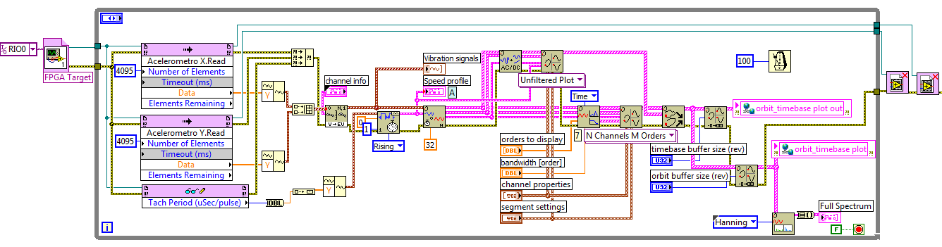
I am developing a project to measure and analyze vibrations of an electric motor with three phases with a cRIO and a vibration module NOR-9234, working the first simulations to verify the proper functioning of the code with a 'NOISE AND VIBRATION SIGNAL SIMULATOR"OR.I use this code for the RT, but run this code. But when I run the code, an error in compiling associated with a delivery that I don't own.
* I use two FIFO in the FPGA for accelerometers ' X and Y ' defined as follows:
-type: target Host - DMA
-Asked the number of elements: 3000
-Data Type: SGL
-Arbitration for writing: arbitrate multiple applicants only.I tried to remove and reinstall he grew and all its pilots, but the remains of the error, include the code I use the RT and FPGA.
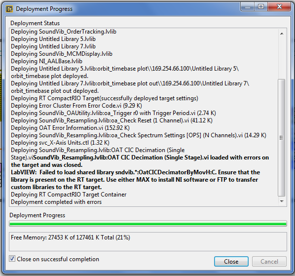
Thanks for your help and any other necessary data asked me.Looks like the sound and Vibration library is not present on the target of RT. In order to install a library on a remote target of MAX, I think that the components of the library must be present on the host PC (as it is the source of the software being installed on the target). Can you open MAX, click on the target distance and expand the software tab? Is there a noise and Vibration library is listed as installed?
Bob Schor
-
Hello
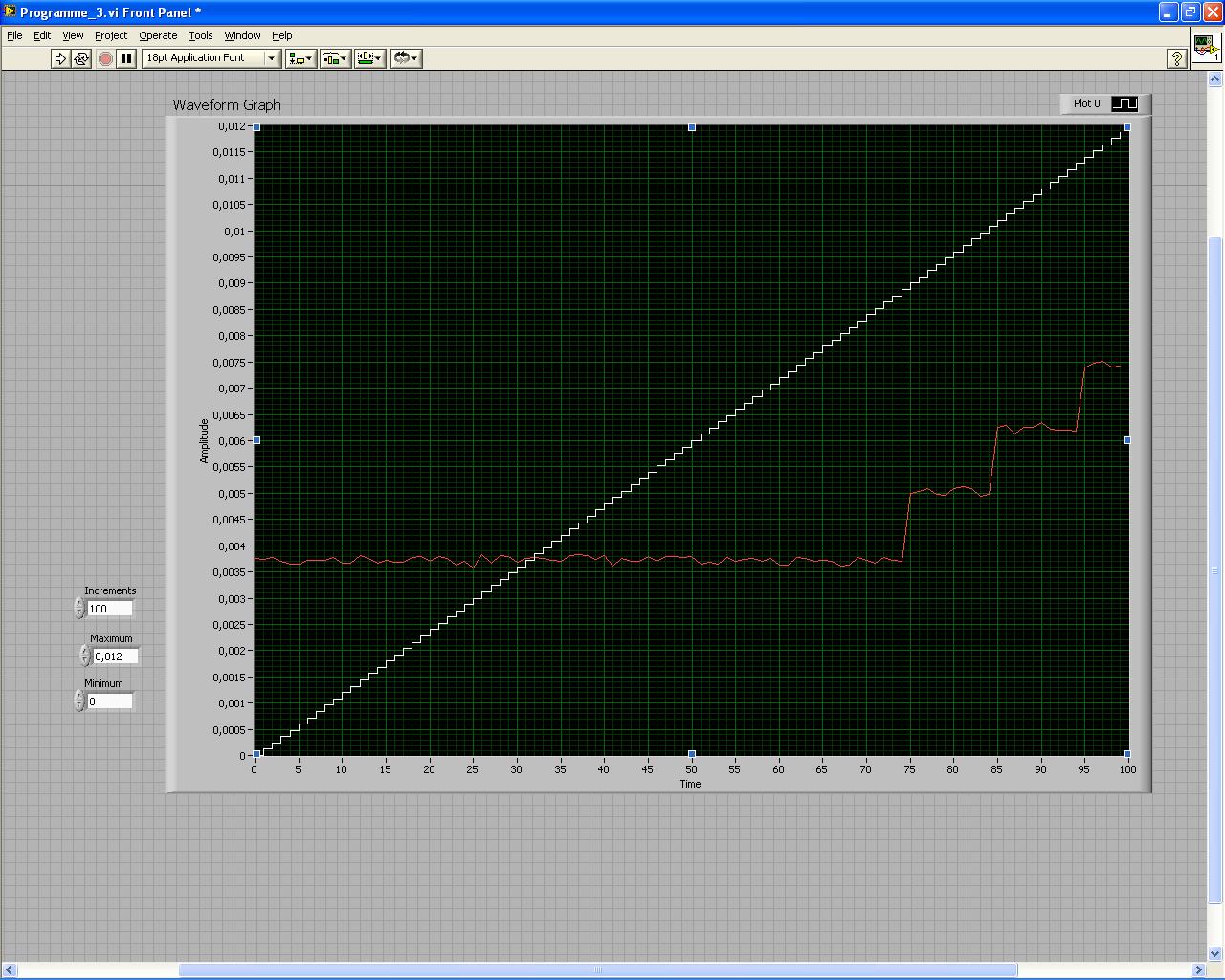
I have been asked to draw the output voltage of the USB-6008 vs the entrance of the NOR-9234. The cards are interconnected, so that the NOR-9234 should read exactly what the USB-6008 case sends to.
But there is a strange phenomenon that happens, the NOR-9234 is unable to read the signal under 3.5mV. I don't know where it comes from, you have some ideas?
This could be the USB-6008, or the NI 9234?
On my graph, the white line is the signal I'm sending to the usb-6008 (ideal signal) and the Red corresponds to the entrance of the NOR-9234.
Thank you
Hi Dibbs,
We look at a few things here - the accuracy of the AO of the 6008, the accuracy of the 9234 AI and the use case of the 9234. The 9234 is a DSA device, so is it is optimized for measurements of acceleration and vibration - not measures of low frequency/DC. The offset of the 9234 error is 7.1 mV and the absolute accuracy of the OD 6008 is 7 mV, up to 34 mV full scale. One thing to do, you can try using the AI of the 6008 to characterize the AO 6008 or use a device optimized for DC, as a DMM measures.
-
Error-200022 occurred at DAQmx start Task.vi
Hello
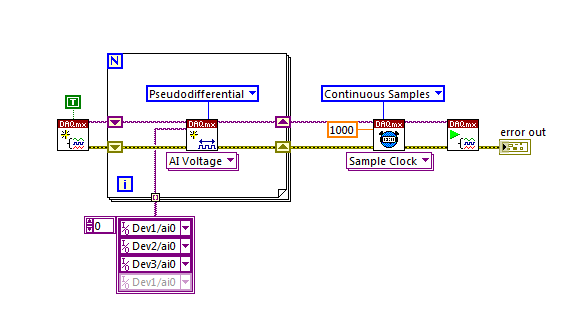
I have peripheral cDAQ and 3 modules that nor-9234 connected.
My program (see attachment) works correctly with only 2 modules, but does not work with 3 modules.
With 3 modules I have this error: "error-200022 occurred at Task.vi DAQmx Start.» "Possible reasons: resource requested by this task has already been reserved by another task."
To solve this problem, please help me
Thank you
Now I understant the error. This is correct (see below)
-
The NOR 9234 keeps it all data in its buffers acquired once it is turned off?
Thank you
Mark
Laughing out loud
Why do yo think it would? The pads would be the RAM.
-
Why my corrected image has non-uniform scaling (mm/pixel)?
I use Vision tools of OR to calibrate nonlinear distortions by imaging a calibration of the spoaced points unfirmly image. I have spread this information of calibration to calibrate a series of images taken under the same conditions as my calibration grid. Then, I need to correct these images before I can make dimensional measurements. (Due to the nature of the processing routine measurement I need that these images corrected first). I also need to enter the actual conversion to the images corrected to this measure of processing routine. I get this by using the Pixel convert to real World.vi for each pixel in the image in order to see any variability within the image. I suppose this conversion value is consistent thoughout the picture but it isn't and ranges from 10%.
Can anyone help explain what might happen?
Secondly, in the correction of my images I only have the interpolation methods: zero order and bilinear. Quadratic and cubic splines are grayed out. Not sure why this is?
Thank you
Dan
Another detail - calibration results NOR are valid within the calibration grid. The numbers get anywhere outside the grid. They get also a little wacky on the borders between the boxes.
Loop through each pixel is a way to do it, but it is slow. The only other possible approach I can think of is to map the image to a corrected image. You can see distortions in this way, but you wouldn't have measurements for them. I might consider to check every pixel on the other, given that the scale factors are not changing too quickly.
Bruce
-
Hello
I run a very basic test on the cRIO:
Signal generator > I (NI 9234)
AO (NOR 9263) > Oscilloscope
The entrance is 1 kHz and I sent the sampling frequency of the AI to 2.5 k, which should be enough to produce a signal smooth on the scope. It does not work like that (I tried the 51.2 k s/s max and that does not work either)

I have dc coupling, I export the NI 9234 clock.
I have attached the code please can anyone help?
* Just to note that I send a sinusoidal signal of +/-4 volts *.
Hey,.
I had a quick look at the VI. Have you tried to move the setting of the rate data outside the while loop? So that define you the flow of data once at the beginning and then to not constantly each iteration?
Alternatively, you can set a flag that signals the entrance to the MOD3 node to determine if the data looks the same before get out you?
-
Power calibration error - Mat * a UJ - 830 s drive Satellite M45
Hello!
I have a problem writing files on my carpet * a writer uj-830 s. My laptop is Satellite M45. When I try to burn a CD or DVD in nore or dla, it gives the power calibration error.
I'm sick and tired of this!
Can someone help me please?Hello
Power calibration error is known to me and revealer of truth he s just doesn't sound right.
For the most part, this message appears if the lens of the player is unable to calibrate in the right position.The goal must always be calibrated before you start read or write the middle.
If this procedure fails, the drive is not able to manage the CD or DVD and get the power calibration error.Frankly, in most cases, the drive needs to be replaced, because AFAIK this dysfunction is not repairable.
Maybe you are looking for
-
I am interested to be a moderator to tell me if I can remove a restricted position. If it can be removed because you do not want the post upwards it then I have no problem with the deletion. I have not found anything wrong with the post when I put
-
Satego X 200 - 21U: question of driver nVidia graphics
A new xp for satego x 200 player is online. It work?He is a driver from ati? My laptop has an nVidia 8700 m gtDownload bad? Do you have anyone tested this driver?
-
custom control represent switch
I'm trying to represent a switch in LabVIEW using a dial. However, I can't understand how to customize my control to watch as I want. I would like him to have options as below / _ \ So I inverted the numbers on my dial so the needle goes counterclock
-
We had WIN XP pro on a computer, but then uninstalled and installed Win 7. We can now use the uninstalled version of Win xp Pro on another computer? Key # [redacted]
-
Using NetConfig to push a new login banner.
LMS 3.2 - RME 4.3.1 I have problems using NetConfig to push a new login banner. I think the question is given that the router or a switch returns a line after the command banner login ^-the router or switch returns a line that says "Enter TEXT messag