Clock counters frequency generator
I recently bought a PCI-6221 card with 2 32-bit counters. I want to read and save two encoders (where the 6221) and analog several entries at the same time... My research has revealed that it is not possible without an external clock (which can be created using one of the counters) leaving only a single counter for my encoders. I noticed that the 6221 has a frequency generator. This generator can be used as a source of clock for counters and HAVE it?
The f
Really? Can I use the sample clock TO the CI as well? I read the opposite on this forum. That's great.
Thank you
The f
Tags: NI Software
Similar Questions
-
Digital output frequency seems to be twice the frequency generated by the basic function generator
Hi Labview forum,
I wrote a program (attached) Labview to generate 3 PWM, square wave, signals that has the same frequency and phase delay right (so that when a signal is off, the other signal is lit. Then the next signal). Everything seems to work fine except that the frequency of the PWM signals generated seems twice as the frequency given to the basic function generator. Anyone have any idea why this is happening? Anyhelp would be greatly appreciated.
Thank you!
Totally agree with the advice of all GerdW than the hardware timing of your hardware DAQ will be much more reliable. That said, part of what you are probably hitting is a little quirk of the primitive delay msec. Requests for 1 msec have long been particularly little reliable (although they * seem * to have improved in recent years, probably due to the better OS support in Win 7 or something).
I did minimal mods to your code with comments from you switch to a timed loop. My quick test showed he is good enough to hit the 1 length of loop of target msec.
-Kevin P
-
How to play a frequency generated through my sound card?
Hi, I'm using Labview Student Edition 7.0 on Windows 7.
I'm generating a signal at a set frequency (in this case about 1200Hz - well within the audible range) and trying to feed this output for my sound card to play through my speakers. However, I don't get any what exit when I tried to use the SIE SO.
Please see the attached VI. I would be very grateful for any help on this matter. It's a few years since I've used Labview and I accordingly this approach as near-novice.
Thank you
Rob
Hi Rob,
I found an example that should help you along the 7.1 version. If you go to the finder example help > find examples, then search for 'sound' it should be a continuous sound output here called VI. See if you can find it and let me know if she does what it takes.
Kind regards
-
Results of increasing frequency generated unexpected behavior of the signal
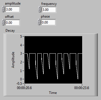
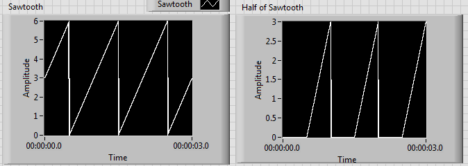
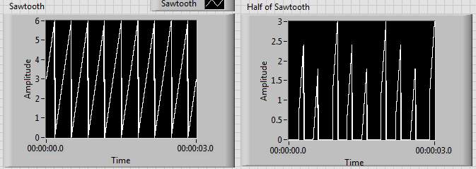
I'm generating a composite using a sawtooth wave, square, signal that produces the desired signal as shown on the left. Unfortunately, when the increase of the frequency beyond 1 Hz, I get undesirable results as shown on the right.
I tried to edit the news of sampling with no luck. I have also tried different methods to produce the desired signal. I noticed that before one of partial components of the final signal enters a relay, the increase of the frequency doesn't create unexpected results. Although, after its passage through a relay, the error starts happening. It seems that the relay is not suitable for higher frequencies, but I can't fix this unexpected behavior.
Frequency of 1 Hz:
Frequency of 3 Hz:
Another method that I tried was to use the "simulate arbitrary signals," even if I was unable to find a way to increase the frequency of the signal that results.
In addition, the signal has this grainy nature that I would like to make it smooth and continuous. Is this possible? I would like finally to reach a frequency of a few kiloHertz.
I have attached the VI.
Any help would be greatly appreciated. Thank you.
The problem has to do with the size of the block and when the relay actually sees the saw tooth cross the threshold.
Solve it, to perform a point-by-point check and build our waveform personalized to each iteration.
-
Best way to generate the software clock for USB-6501 of Measurement Studio for c# VS2008
Hi all
I wonder if there is a better way to generate a clock software for USB-6501 of Measurement Studio for VS2008 in C Sharp?
I have developed a clock using C Sharp "Thread.Sleep (msecPauseTime)"; and statements to switch digital output high and low. There are a few things I noticed in creating a software clock in this way:
- The smallest delay by the Thread.Sleep command time is 1 millisecond (which means higher clock period is 2 msec-500 Hz, not holding not ball account no. 2 below).
- Sometimes the delay I see on an oscilloscope is considerably longer than the delay that I specified in the sleep command.
In my application, I create signals (a clock, a latch enable and data series) to control what an attenuator step through the USB-6501 RF connected to a USB 2.0 on my computer. This particular step RF attenuator can accept clocks with frequencies up to 10 MHz, so I would like to generate a software clock (without having to connect to an external clock to a line of input on the USB-6501) which is closest to this maximum frequency, and I think that the USB2.0 line could handle clock speeds over 500 Hz. Also, I would like to know why the delays that I see on the scope are sometimes longer than the time specified by the Thread.Sleep command. Is it caused by the suspension of the execution of my program processor for something else, as I suspect? Of course, this isn't a big deal, because it does not affect the time as my serial data and pieces change compared to my clock. However, I would like to know why it does this.
I appreciate your help.
Thank you
Jonathan Becker
Doctoral research engineer
Carnegie Mellon Silicon Valley
Jonathan,
Since the USB-6501 DIO is software programmed, you are at the mercy of the planning of the operating system and won't be able to work reliably with an external clock in the software.
You can try to set the priority of your thread 'generation of clock' to improve performance, however, because Windows is not a deterministic operating system, there are still no guarantees. Operating systems are not required to honor the priority of threads. You can find examples and information on the definition of the priorities of the threads in c# here:
http://msdn.Microsoft.com/en-us/library/system.Threading.thread.priority.aspx
Kind regards
-
Jitter in response to signal generator of digital dashboard by using trigger nor tclk with digitizer
I've written a VI that uses NEITHER tclk to synchronize a generator (PXI-5422 named FGEN1) and a digitizer (PXI-5122 named DIGITIZER1). There is also a clock card TIMING3 generating a digital camera.
It seems that can probably be explained by the way TCLK to synchronize, but I don't understand all the details. Could someone help explain this to me?
You are right. NOR-TClk ensures that all synchronized devices start at almost at the same time, to the same sample clock, with timing very tight. Sometimes, the level of synchronization with the devices OR TClk-synchronized beats at the level of the synchronization of the instruments of some competitor channels in the same device. But this is not free, there are compromises and added additional jitter for trigger response time is one of them. Here is an attempt to explain why:
When you use NEITHER-TClk and send a trigger, the devices will respond to relax on the next cycle of the clock once made the trigger signal to the device. Let's say you have several devices all of them even configured with the same clock frequency. You block the signal of PXI_Clk10 using their PLL, so they drift out. But each unit's clock edge will be off, clock +-0.5 cycles. If you send a trigger to each of them, they will respond on the next clock cycle whenever it is, after the arrival of the relaxation to each device with different propagation times, whatever they may be. You get a single clock cycle of jitter on reaction of device to set it off.
When you use NEITHER-TClk, several things happen: all devices are locked on the PXI_Clk10 signal to eliminate drift. The device clocks are then adjusted to a period level secondary clock. Very very tight. Then a clock signal common, slower called TClk is produced inside the devices. All the generation of trigger are delayed to be sent to the next rising edge TClk, and all consumption trigger is delayed to be received at the next front descending TClk. This way you make sure that propagation delays don't mean one of the devices does not react to the trigger until the next clock cycle.
That's why you see jitter above the reaction time of relaxation. When you add devices with different clock settings, so the frequency of the TClk can be slower for a divisible frequency in the device clock frequencies everything is possible. This causes the trigger jitter of reaction time be even slower!
I hope this helps you understand what you see.
-
How to get a regular clock (100 MHz, 10 MHz to 20 MHz) of the NI 4462 PCI?
Is it possible to extract a regular clock, high frequency of the 4462 OR?
I need to synchronize with another card (a PulseBlaster), which requires a 100 MHz clock: every card can be the main source, but they must stay perfectly synchronized.
(Both cards have on-board crystal oscillator modules of 100 MHz; one of the PulseBlaster is nested, would be so easy to connect a source external intead)
I use the PCI version, so the star PXI 10 MHz clock is not available. The 10 MHz or 20 MHz clocks that DAQmx usually exports seem not to be available for routing on this device.
I can't use the Sampleclock, because it is variable (~ 25.6 MHz, changing with sample-freq) and because it is not active when the 4462 is actually measurements.
In addition, this clock must be either 100 MHz, or a whole simple fraction of it (e.g. 10 MHz, so that a PLL can re - generate the 100 MHz).
At the present time, the best option seems to be to solder on the 4462 output pin quartz oscillator - but it's a really ugly way do... has anyone had an experience to make relevant changes?
Is there a better place to connect to? I would prefer to use the RTSI bus connector, but despite tempting advice in the documentation, it seems not possible to get out of the 10/20 MHz master time base: there is
an axis called RTSI7/RTSI_OSC, but it is a permanent decline.
Thanks for your help.
Nick Dear,
Thanks a lot for your help. As you say, this confirms what I already knew.
But we really need keep everything in harmony. So, here is what I did, which should hopefully help someone else in the same position.
The circuit is very simple, using a FIN1001 LVDS line driver. It is a SOT-23 package. Connections are the following:
* Din connects to the output of oscillator 100 MHz (TC0-2104, pin 4).
* Gnd connects to the Earth (C210, lower)
* + 3v3 connects to the more accessible place, that TCO-2104, PIN 6. [The 3V3 regulator is on the back of the map]
* FIN1001 food is decoupled with a 0.1uF adjacent capacitor.
* Dout + and Dout-are connected to a short (30cm long) of the unshielded, twisted pair made of wire 0.7 mm PTFE. (Z ~ 110 ohms)
Photograph is attached. The SOT-23 package is physically secure, with a tiny drop of cyano, C210 and mounted on his back.
The receiver uses a FIN1002 receiver, finished with 100 ohm twisted pair and uses a 74VHC04 to convert 3.3V 5V TTL.
It is mounted on a 14 pin DIL socket, to plug directly into the socket on the other card PCI which normally has its own oscillator module.
Result: everything works, and I have a 100 MHz clock available to drive the other timing card.
-
Frequency control of NOR-9476 on the cDAQ-9188
I am using a cDAQ-9188 with a NI 9476 module, and I would like to control the frequency of the digital signals that the module was released. I tried to use the example of Pulse Train digital continuous with control of the frequency, but impossible to select the 9476 since there is no internal counter, and when I change the 'Digital output' task, the frequency control disappears. Is it possible to use the internal counter of frame to control the output frequency of the 9476? I need to get out a range of 0 to 1 kHz.
Most of my program would output a digital signal of a certain frequency every second in real time from a given table. For example, if I have an array of [10, 20, 15, 100,...], it generates a model of up/down of 10 cycles per second for a second, followed by 20 cycles (with a shorter period) for a second, then 15 cycles per second for a second, and 100 cycles per second for a second.
I tried to use avoiding to do, but it was very slow, with a delay of 63 ms between each cycle, when I wanted a 1 ms delay.
CDAQ-9188 has 4 counters built in, but you cannot access it by using the NI 9476-, but the NI 9401 module can access the built-in meters.
The good news is that you can always generate your pulse train, using counters, it generate on the PFI lines on the chassis itself and not through your module. If you need to generate more than a pulse train, or use all four counters, you will need the module NOR-9401/9402.
In order to get the speed, you will need to use the capabilities of hardware counters timing.
I hope this helps!
For more information:
-
Nor-5406 & nor-5112 frequency sweep
Hello
I have a frequency generator (5406) that I use to generate a frequency sweep (1 ms by frequency).
When I read the signal with a digitizer (5112) it seems that the duration at each frequency is bad.
I've attached a photo (I hope) to identify the problem.
The sinus begins here, at a frequency of 20 kHz to 1710 (coordinates, left panel).
Because I taste 3 MHz and that each stage of the frequency is 1 ms, I expect to see the next step to 4710.
That is not the case (right panel)
Any help appreciated
Also attached to this message is a copy of a part of the block diagram.
Thank you
Hello
The explanation of what you see, is that even if you ar affecting your sample NOR-5112 3 ms/s, you are actually sampling at 3.03MS / s.
If you are referring to the specs of the device , you will notice that this Council has a maximum rate of 100MS/s of sampling and can sample at a rate decimated 100MS/s/n where n is an integer between 1 and 100e6. If the sampling frequency is not feasible by the digitizer, the pilot will force the value of the next achievable sampling frequency that is higher than what you asked. In this case n = 33 and your actual sampling rate is 3.03MS / s.
If by your calculation for 1ms, you will get 3000 samples at the rate of sampling or 3 ms/s. This would pass to 3030 samples at a rate of 3.03MS / s. I think that this corresponds to what you see on the image. To be certain of the current rate of your Board is sampling, try to use VI "niScope sampling rate" to query the actual sampling frequency of your digitizer.
-Jennifer O.
-
generate signalexpress of digital output or 6009
Hello
I'm a user of Labview SignalExpress rokkie. I would like to generate outputs digital, but when I try with N samples or samples continious it does not work, it gives the error which is
Error-200077 occurred to the DAQ Assistant
Possible reasons:
Measurements: Requested value is not supported for this property value.
Property: SampTimingType
You asked: Sample clock
You select: On-demandAlthough I can generate a sample so could you please help me on this problem?
Kind regards
ERS
As mentioned previously, the USB-6009 case supports the outputs digital NI. "N samples" and "Continuous" generation modes are available only for devices that are able to use a clock embedded to generate samples. Input analog on USB-6009 uses can use an on-board clock and can thus use modes "Continuous" and "N samples. The better you will be able to do with the USB-6009 case is to switch the value on and with a timing of software. A solution would be to use a step DAQmx Generate to set the high value, a stage of execution to allow reuse of the material, and then an another DAQmx generate step to set the bass line. Run this in a loop and you'll get something of a digital pulse train (although it is not terribly pretty.) It will be quite slow and very non-deterministic. This means that some iterations may take only a few milliseconds, while others may take much longer.
Kind regards
-
How to generate pulses on the digital i/o lines? USB-6211 labview 8.5
I want to generate a 5ms pulse on one of the lines of digital output that will be more used to delay the acquisition, DAQ.
Thank you
You will need to use counters to generate a digital pulse. I ask you to take a look in the examples that come with the DAQmx driver (in LabVIEW, help goto-> find examples). You can look for impulses and select generate Dig Pulse.vi. If you have questions, after return!
-
Data acquisition period log rate Counter
I measure and record the duration of a pulse train of digital entry (entry to the NI9421 card on a DAQ, series "C" chassis and recorded via LabVIEW SignalExpress 2009). The acquisition stage 'Counter period' is configured to use ' 1 meter"measuring method.
In order to save the data that I have to use ' 1 sample (on request)"acquisition mode.
When I go through the saved data, how can I determine:
(a) the sampling frequency of the recorded data points?
point b) absolute timestamp of all the data?
The log file has no information concerning the frequency of recording and my experiences, it seems to change based on the measured period of entry.
Any ideas?
Hi a.yearsley,
Counters on cDAQ chassis 1st generation (9172) do not support measures clocked sample period. I assume you are using this chassis since you mentioned that you have the module in slot 5 or 6.
Your County of edge is very similar to the method of meter high frequency 2. In both cases, you specify a length of time and count the edges of your external signal during this period. The 2nd counter is used to generate the gate signal for the duration of time specified. Your error with this method is up to 1 time of the external signal, it is more commonly used with higher frequency signals (I don't know what is the frequency of the signal).
The standard method of 1 meter counts the number of ticks to a time base internally (80 MHz) for a period of the input signal. As the signal itself, it is what is blocking the measure, the sample is locked in the buffer on the edge of the signal and is not clocked independently. If you wish, you can configure the implicit synchronization, which gives you a period measured for each face of the input signal.
Taking the stage above an idea more far, you could just set up a task to County of edge with the time of 80 MHz as the source database. Use the external signal as a sample clock. The only difference between this and using the standard period with implicit synchronization measure is that the counter is not reset after each sample. This could make it easier to follow if you want to save a sample all the x seconds (that is, once the total passes a certain value). You can find the period by subtracting the consecutive numbers and multiplying by the period of the time base (12.5 ns). The meter would be turning after 53.69 seconds about, but if you read the County under the name of U32 there will be no problem with the subtraction (0000 - FFFF = 1 if the numbers are 32).
If you're on cDAQ chassis 2nd generation (e.g. 9174, 9178, 9188), then you have not actually taken in charge for a period clocked sample measurement. You can choose to enable a medium or not. The user manual 9178/9174 has diagrams showing the extent of the clocked sampling frequency that is essentially the same thing (the driver reverse the measurement period for the frequency). Must be guaranteed at least 1 m from your external signal between the sample clocks, if you use this method. The clock can come from many sources - I would probably recommend using another counter to generate.
Best regards
-
Synchronized not regenerated multifunction AO AI
I am trying to build a VI that reads and writes a signal simultaneosly to use as a test of the device. I want the signal to be non regenerative and I want to read 80kS/s with at least 4096 samples.
I built my VI begin with the standard model of producer-consumer and the example AO AI multifunction located under "hardware input output/DAQmx/synchronized/multifunction" but with minor modifications to make it non-regenerative. This however does not work because there seems to be a discrepancy between the two signals after the first few iterations. Initially the signals overlap, but then I get a period. For example if the sample rate and of the samplesize 1000 superimposed signal for a short period when yields but then a delay of environ.25 seconds appears. There are also various errors of buffer all indicating that the buffer has been closed or crushed before that samples could be read. If there is someone who would know how to solve this problem, I would be extremely grateful.
I'd appreciate also all tips on how to be able to update the sampling frequency and size in real time.
Best regards
Felix Turner
Hi Felix,.
Welcome to the forums EITHER! The part of the synchronization of your code seems pretty good assuming tasks of HAVE and AO are running on the same device - you are triggering one task out of the other, so they should start at the same time (if they are the same device, the time will be the same for each clock so you shouldn't get any drift over time). Another way to synchroinze the two tasks (because they're going at the same rate) would be to simply share the sample between tasks clock.
A few problems I see with the code:
I think that problems of buffer problems come from the fact that the tasks of HAVE and AO are in the same thread. DAQmx Write is a blocking call, so in your code it prevents DAQmx called Read until enough space became available in the buffer output to write the desired number of samples (1000 in your case). In the meantime, looks like the analog input buffer is completely filled. You could try to increase the size of the buffer, but you can also consider the two tasks running in parallel loops.
In addition, samples of reading (-1) will return some data are in the input buffer. It would probably be a different number of the number of samples that you write by loop iteration, so the data may appear sync when it is read.
With respect to the number of samples to read and write by loop update, it is editable running so everything you need to do is put the control inside the loop (you can put a local variable outside of the loop to the initial settings).
The PCI clocks rate, I / ao sample is not modifiable at run time, but what you can do is to use a meter to generate a sample for both tasks clock (just use the internal output as the sample for each task clock). This example shows how you can change the rate of a performance counter on the fly.
Put it all together, here's what I'll try:
I would put both DAQmx tasks in parallel loops. Instead of sharing a trigger of departure between the two tasks, use one of the counters to generate a variable frequency sampling clock to use. The tasks of HAVE and AO must begin before the meter.
You should also probably use the number of samples to read the DAQmx Read entry so that each iteration of the loop will be matched with the data written in the previous iteration of loop AO. If you are not careful when implementing the variable number of samples to reading parameter, you could end up with a race condition where single loop updates to read samples and the other is not updated until the next iteration. Usually Of functional Global Variables are used in situations like this, but another idea might be to adjust the size of the buffer AO so that we can ensure that the loop AO will always run before the loop to HAVE it. You can place the control inside the loop of the AO and the local variable inside the loop to HAVE it.
Feel free to post if you have any questions!
Best regards
John
-
Acquisition of NOR-6602 delay and buffer overflow
Hello world
I use an NI PCI-6602 to record photon arrival times. Basically, it counts the number of rising edges on the sample clock 80 MHz which occur between two rising
edges on the photon TTL signal. The array of integers can be converted at a time by multiplying by 12.5ns. Please find my VI for the task and its attached Subvi.I have two problems:
(1) I want to do this same measure for two photon detector channels. I've set up two independent channels. My goal is to correlate the signals with a gap between them. I am able to implement a delay in the software, but my data there seems to be a small inherent delay between the start of each channel.
The amount of the delay is seemingly random and occurs in the positive and negative direction. In VI I joined, I tried to use the start of arms in order to get both channels to start acquiring at the same time, but this reduces the severity of the delay, it has not removed completely. There is always a delay of 1 to 500 microseconds. I have implemented the trigger arm to start properly, or there at - it another way to solve this?(2) I get an error message indicating that "the data has been overwritten before it can be read by the system. The number of samples that have been collected before this error varies and also varies between the counters on the Board. I had a theory that the transfer of sample rate was not good enough, but according to the manual, the transfer rate should be approximately 2000kS/s. It is more than enough as the photon count rate is less than 50 k/s. The PC that I use has a PCI graphics card too. Is it possible that is to limit the frequency of sampling? Here are the specs of PC: processor Intel Pentium D (3.0 GHz), 2 GB of RAM, nVidia GeForce 7300 graphics THE.
Thanks in advance.
Hi James,
I think you might be interchanging the words "metering" and "sampling".
The counting begins with the relaxation of beginning of arm, which should be at the same time for both channels (with perhaps a shift of 1 tick, who would be 12.5 ns on the 6602). Count refers to increment the register of account of material at each tick of the input terminal (80 MHz base time in your case).
Sampling of the account register will take place at different times on each dependent channel when the photons are detected. So the temporal measures on each channel will be different, but if a photon should occur on each channel at the exact time you would get an identical timestamp on each channel for a sample. Sampling refers to the value of the register count in a buffer you can lock read later in the software.
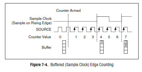
This image (from theM-series user manual actually, but the 6602 should work the same way) watch your use case:
The time that the meter is armed is identical between the chains, so each counter at some point value would be equal. The time sample clock are not identical on each channel, so locked into the buffer values don't would not the same.
Using the same external signal to sample some registers simultaneously count shows that relaxation of arm early works (in other words, if you give the same sample clock counters, you get the same results). If the beginning of the arms did not work, you will see different results on each counter even with a same sample clock (the sample clock not to arm the meter). Out the relaxation of beginning of arm would confirm this point - arm tasks in the software (which is what happens with no beginning configured trigger arm) will give unpredictable delay between each task starts - you will see a difference between the channels, even with a sample clock shared.
Looks like the problem is that you could have if wait photons occur on the two separate channels at most close at the same time? You can try out photon detector to confirm whether or not there is a current backlog of the scope. Looks like it is - but this isn't what you're trying to measure? Expect photons to be detected by each channel exactly at the same time?
Best regards
-
NI 6552 Signal Express sampling rate
I'm generating multiple signals for Signal Express. When I run them, some work well and others not, in other words, for some changes in sampling rate signals! Thera are two options in Signal Express: 1. read file waveform 2 sampling rate. to manually set the sampling frequency. In both cases, the rate is changed when I run the waveform of my 90 MHz to 100 MHz.
Any ideas?
Hello
The internal clock on the 6552 is generated from 200 MHz time base; Is that you can generate the frequency of 200 MHz/N where N is from 2 to a large number which takes up to 47 Hz. The driver for the Board of Directors will force the neerest value, so if you swipe from 90 Mhz to 100 MHz frequency, you will get 100 MHz in all cases. There is more information about the synchronization on the specs here:
http://digital.NI.com/manuals.nsf/WebSearch/E4C93B141B71ED93862573CC005E8EA1
Once, you run your project, Signal Express should show you the corced value, you can use this to read the actual frequency generated.
I hope this helps.
Juan Carlos

Maybe you are looking for
-
Transferred from one country to the other. Cannot update or buy anything. Any suggestions?
I bought my Mac and my iPhone in South Africa and the iPad in Mauritius. Currently, I live in South Africa. When I try to update certain applications it tells me that the application was purchased by another user or has been cancelled. Also enter th
-
One of my friends bought an all in a desktop computer VAIO, a Sony.com VPCJ118FX/B, to be computer to be used in paris (France), so with a QWERTY keyboard.As she did not want to be disturbed, she bought in her country a Sony service center set of QWE
-
Impossible to select the time range in dropdown menu-foglight PASS UI.
Hello I'm new to foglight and is having a little problem with the user interface. I doubt if I'm in the right place to ask this question. I use Foglight for SQL Server 7.0 v. Under UI, there is a drop down for the time interval, which, in my view, do
-
Paste the image into the text stream
In the past, my understanding is that you need to copy your image to the Clipboard, place your cursor about to insert and then when you paste, your image will be placed there in the text as part of your text... but you have to drag the image down, so
-
I've updated the preferences in captivate 9 for Quiz default labels. I want to "Skip: ' for show 'Next' - I entered my preferences.In the quiz Panel, it says 'Skip '. How can I change this?Thank youNorma