Clock or 6587 external in (simple nerve - ADM)
Hello
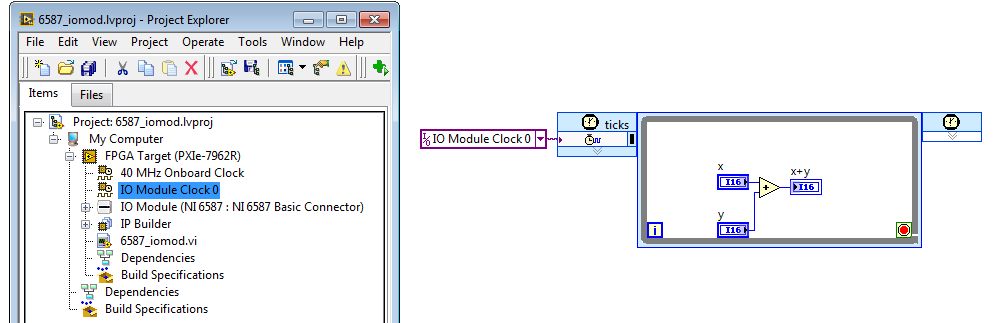
I have a PXI fpga 7962R module and or 6587 adapter. I want to use the external clock to set up a simple Adder xilinx Ip core. I have the e/s 0 clock input an external clock of 20 MHz with 3 V pk to pk. I then attached to single loop timed cycle and fpga clock allow VI and set up my IP core inside the loop. I haven't used the fpga disable vi since I want continuous running vi.
now the project, but on the spot and I don't see any other except top 40 MHz clock being implemented. At the end of the compilation, I received an error which fpga and host could not communicate. the clock z not connected or is nott generated according to specifications. What could be the problem?
The project you attached had not included in FPGA vi so I am unable to tell if you were using the IOModClipClock0 correctly.
Anyway, attached is a draft that has the IOModClipClock0 added to the target, and an FPGA VI, who uses it to run in a single clock cycle logic loop.
Tags: NI Hardware
Similar Questions
-
Clock and hw external trigger with USB-6210 on Linux with NOR-DAQmx Base?
I have two devices USB-6210 I need to synchronize so that they both collect data exactly at the same time. I was told by support OR I can send the clock off Dev1/PFI4 and have the two USB-6210 s read the clock in through their own PFI0. I also want to trigger data collected for each device by sending a trigger off Dev1/PFI6 and have two devices to receive the signal on PFI2.
All my attempts to try this are filled with error messages and my research online seem to say that's not possible with USB devices on NOR-DAQmx Base 3.4.0f2 on Linux.
I "ve tried using example AI programs and those who do not seem to work either for external clocks. Here is the code I tried:
#include "NIDAQmxBase.h"#include

#define DAQmxErrChk(functionCall) { if( DAQmxFailed(error=(functionCall)) ) { goto Error; } }

int main(void){    // Task parameters    int32       error = 0;    TaskHandle  taskHandle = 0;    char        errBuff[2048]={'\0'};    int32       i;

    // Channel parameters    char        chan[] = "Dev1/ai0";    float64     min = -10.0;    float64     max = 10.0;

    // Timing parameters    char        clockSource[] = "/Dev1/PFI7";    uInt64      samplesPerChan = 1000;    float64     sampleRate = 10000.0;

    // Data read parameters    #define     bufferSize (uInt32)1000    float64     data[bufferSize];    int32       pointsToRead = bufferSize;    int32       pointsRead;    float64     timeout = 10.0;

printf("Calling CreateTask...\n");    DAQmxErrChk (DAQmxBaseCreateTask("",&taskHandle));printf("Calling CreateAIVoltageChan...\n");    DAQmxErrChk (DAQmxBaseCreateAIVoltageChan(taskHandle,chan,"",DAQmx_Val_Cfg_Default,min,max,DAQmx_Val_Volts,NULL));printf("Calling CfgSampleClkTiming...\n");    DAQmxErrChk (DAQmxBaseCfgSampClkTiming(taskHandle,clockSource,sampleRate,DAQmx_Val_Rising,DAQmx_Val_FiniteSamps,samplesPerChan));printf("Calling StartTask...\n");    DAQmxErrChk (DAQmxBaseStartTask(taskHandle));printf("Calling ReadAnalogF64\n");    DAQmxErrChk (DAQmxBaseReadAnalogF64(taskHandle,pointsToRead,timeout,DAQmx_Val_GroupByChannel,data,bufferSize,&pointsRead,NULL));

    printf ("Acquired %d samples\n", pointsRead);

    // Just print out the first 10 points    for (i = 0; i < 10; ++i)        printf ("data[%d] = %f\n", i, data[i]);

Error:    if( DAQmxFailed(error) )        DAQmxBaseGetExtendedErrorInfo(errBuff,2048);    if(taskHandle != 0) {        DAQmxBaseStopTask (taskHandle);        DAQmxBaseClearTask (taskHandle);    }    if( DAQmxFailed(error) )       printf ("DAQmxBase Error %d: %s\n", error, errBuff);    return 0;}
When I run the resulting program, I see this:
$. / acquireNScans-ExtClk
The CreateTask call...
Call for CreateAIVoltageChan...
Call for CfgSampleClkTiming...
Error-89136 DAQmxBase:route specified cannot be satisfied, because the hardware does not support it. For example, a clock and a trigger can be imported via one of the PFI lines by using a USB-6210 on Linux with NOR-DAQmx Base? A clock and a trigger exportable via one of the PFI lines?
If so, does anyone have the code example illustrating how to do this, or can you at least tell me the names of the lines ("PFI0/Dev1" or other) so I can try again?
Clues or suggestions would be helpful.
Thank you
-Tom
The clockSource in the example specifies an output rather than an input channel channel. Change source "/ Dev1 / PFI0" solved the problem.
Please close this post.
-
cDAQ HAVE task using external clock
Hi, I am trying to use a clock signal on a line of PFI in order to generate a clock, but at a lower rate, for a task to HAVE. I run into many issues that I can't explain.
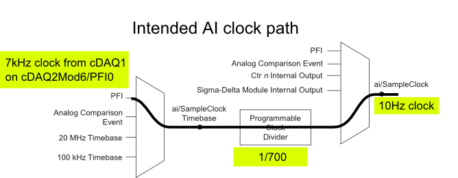
I have a cDAQ-9172 with an entrance module analog (9225) in the Groove 3 and a digital input module (9411 - 2 MHz DI) into the slot 6 (where the PFI lines are accessible). I want to use an external signal on et0/PFI0 to act as the clock for an analog input on the 9225 task. This signal comes from the cDAQ anothr chassis and is too fast for the task to HAVE it, so I intend to use the time base entrance and the divider to clock (as shown on page 31 of the cDAQ-9172 manual). See picture attached for a graphical representation of my problem.
If I have the wiring from the signal "/ cDAQ2Mod6/PFI0" in the DAQmx timing VI, get the error 200414 saying that "required sample clock source is not valid." It is strange because it is listed as "Direct route" in Max (the VI of polymorphic DAQmx Timing is configured as 'Sample clock') Q: why this route is not suitable for the task?
If I use DAQmx Timing property node and change the Source 'Sample clock Timebase' to ' / cDAQ2Mod6/PFI0 ", the task starts without error, but the separation seems to be forced to 256. If I try to change the properties of the separation of the time base, I get error-201100. Try to change the 'sample clock rate"doesn't have any impact on the task and the remains of divider"256 ". Q: why the 'Programmable clock divider"locked to 256 when using the PFI line or can you just not program directly?
I came across another error is the minimum speed on the PFI line. If I have the wiring (for the SamplClock Timebase) lower at 1 MHz, LabVIEW returns error-200077. The error message indicates that the minimum value is 1 MHz. 9172 manual shows the clock 100 kHz is an option for the time base, certainly less than 1 MHz. Q: What are the limits of upper and lower frequency for a clock signal on the line PFI for the ' Timebase AI/SampleClock "?
I looked on the site and in the DAQmx documentation for further explanation, but I have been unable to explain these strange behaviors. What are the barriers to entry of Timebase PFI and the time base "Programmable clock divider" preventing me to reach my goal here? If I can't do it directly, can I use the PFIn signal to feed an internal counter (to act as the clock divider) which could then generate the clock WAS at the rate I want? This method would allow me to perform a division arbitrary clock (unlike the ' 256', which seems to be forced on the PFI as a Timebase SampleClock.)
Finally, something seems odd that I can make an acquisition to 10Sa/s max but when I start a task using an internal timers of the cDAQ9172 and ask a 10Sa/s rate, the task really gives me a rate of 1612.9 sample/s while using the 12.8 MHz clock and a divider 7936 timebase. Q: Why can't the task to 10Sa/s?
I use DAQmx 9.7.0 and LV2012 SP1 (and I tried with 9.7.5 but I got the same results)
Thank you
Olivier
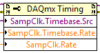
I got additional help Friday in another engineer at NEITHER and the solution to my original problem is actually very simple to get the clock from an external source path:
The idea of picking a PFI line for the basis of 'time' and the 'Programmable clock divider"(in fact, DAQmx calculate this number based on"HAVE sample time clock"and"Sample clock HAVE") works by using the node property below:
(SampleClock.Source cannot be resolved until the task is clerks/reserved, but the default option seems to be the time base that works well in this case.)
The question that I described earlier with the 9225 comes the module properties and the fact that it is a "Module of Sigma - Delta". That the module usually generates its own time of 12.8 MHz base clock (page 14 of the document 9225 # 374707) and the clock divisor is much less possible values than the other modules (must be a multiple of 256). It may use a different time basis from a PFI line, but it must be between 1 MHz and 13.15 MHz.
So a main clock between two chassis and tasks running at different rates of sharing should be easy and simple with most of the modules. With AI modules with Sigma-Delta converters add additional limitations and the master clock for the time base frequency must be selected to accommodate these module as well.
Another good news is that the Simulator seems to bear all these details and DAQmx (9.7.0 in my case) generates the same errors when you use a simulated chassis if you use real body. Play well!
-
DAQmxCfgSampClkTiming sampling rate for external sources
I'm looking at the example of Synchronized_AIAO_Shared_Clock.c to http://zone.ni.com/devzone/cda/epd/p/id/2352 . This example creates a string of tension that HAVE streams at 10 kHz, and then creates a tension AO channel that is bound to the sample clock HAVE to synchronize channels. I use this example to understand the use of DAQmxCfgSampClkTiming here. This is the corresponding code (comments are mine):
Create a channel of tension HAVE will work continuously at 10 kHz
DAQmxErrChk (DAQmxCreateTask("",&taskHandleRead));
DAQmxErrChk (DAQmxCreateAIVoltageChan(taskHandleRead,"Dev7/ai1","",DAQmx_Val_Cfg_Default,-10.0,10.0,DAQmx_Val_Volts,NULL));
DAQmxErrChk (DAQmxCfgSampClkTiming(taskHandleRead,"",10000.0,DAQmx_Val_Rising,DAQmx_Val_ContSamps,1000));
Create a tension AO channel, and then attach the clock of the chain in tension of the AO for the sample clock HAVE
DAQmxErrChk (DAQmxCreateTask("",&taskHandleWrite));
DAQmxErrChk (DAQmxCreateAOVoltageChan(taskHandleWrite,"Dev7/ao0","",-10.0,10.0,DAQmx_Val_Volts,NULL));DAQmxErrChk (DAQmxCfgSampClkTiming(taskHandleWrite,"ai/SampleClock",1000.0,DAQmx_Val_Rising,DAQmx_Val_ContSamps,1000));
.. So what I'm trying to understand here is how to interpret (1000.0) sampling rate argument in the second call to DAQmxCfgSampClkTiming, where the canal AO is related to "AI/sampleClock. It seems to me that this argument must be meaningless, other than perhaps to determine the size of the buffer, since by definition this AO channel will clock on a sample of every time that AI/SampleClock rises. Then maybe someone can help me understand how this argument is used...
But in all cases, the docs say "If you use an external source for the sample clock, set this value to the maximum expected rate of the clock." In this case, the clock is set up a few lines earlier at 10 kHz, so is not this 'evil' in the second call to DAQmxCfgSampClkTiming, a sampling rate of 1 kHz is specified (much less than the maximum rate of sample expected)? What is the consequence of this?
Thank you!
-Dan
Hey Dan, some big questions you've got.
You pretty much put the nail on the head with your guesses. The size of the buffer is based on the resolution of data acquisition in combination with the sampling frequency that you specify. Think of it as an implicit in the size of the buffer declaration (but it is certainly an explicitly define that, if you wish).
As for your second question, which relates to new back to the size of the buffer, except that this time it is for the use of an external clock source. Given that the material has no implicit way to know the frequency of clock of this external source, it asks you to specify explicitly the maximum frequency so it can create a buffer of the right scale size.
-
Problems of acquisition & visualization: fails at 100 Hz, OK more low or more freqs
Hi all
I have some data acquisition & visualitzating problems.
The acquired data is a voltage (0 - 10V) from RDP LVDT & conditioner. My pourpose is simple: I want to gain everything by visualizing and recording to disk. I use a card BNC-2101 & 6062E. I also use LabView 8.5 on Windows XP s.p.3. I tried three ways: my own .vi and examples of LabView with internal clock and the external clock. They all consist of two steps: aquire, visualize data on a graph. and my own .vi also saves the data in a .lvm.
On the first try, I was able to acquire data with sample on request mode. But I want to get to a known frequency, so I put 1-sample (controlled HW). I set the frequency and the number of samples as well as the number of samples is of approximately 1/5 of the frequency, for a rate of graphics path 5 times / sec., BUT I found the following problems:
(1) for the acquisition in the low frequencies, say 50 Hz, there is a large gap between read data a shown in the data graphic: from 2 to 8 seconds.
(2) for the acquisition to high and very high frequencies, say 20 kHz to 100 kHz, the graphic works OK. But in this way, the file I'm writing is too much. I don't understand why when I put the computer work harder, with more data, it appears without delay.
(3) for the acquisition to 100 Hz, it does not work. An error (just know don't remember the #, is one who says this time-out has been reached whithout having given to read aviable). 99.9 Hz works, but not at 100 Hz or 200 Hz. I really don't understand this point.
Can someone help me please?
Thank you for your attention,
usuario
Just writing to tell you that we have tried with another computer and had no problems with the hardware and the same .vi.
And have had no problem for the las 2 months.
Thank you all for your dedication.
-
DAQmxWaitUntilTaskDone overflow error
Lately, I've been running into a problem with the DAQmxWaitUntilTaskDone command.
I'll put a program that generates a square (of sorts) wave, and I find that if I leave the program running for a day or two, I get an error of overflow on the DAQmxWaitUntilTaskDone command. I tried with different (including-1) values for the value of TimeToWait, but I get the same error. What could cause this?
This is my code so far. FWIW, I use a NOR-6259.
190 publicStatus = DAQmxCreateTask ("", taskHandle)
200 taskIsRunning = True'Add a digital output channel to the task.
210 publicStatus = DAQmxCreateDOChan (taskHandle, "Dev2/port0 / line8:16","", DAQmx_Val_ChanForAllLines ")
"Configure synchronization for sample clock and the external signal.
220 publicStatus = DAQmxStartTask (publicOutputPulseTaskHandle)
230 publicStatus = DAQmxCfgSampClkTiming (taskHandle, "Ctr0InternalOutput", # 1000000, DAQmx_Val_Rising, DAQmx_Val_AcquisitionType_FiniteSamps, numSamplesToWrite)'Write the table of values.
240 publicStatus = DAQmxWriteDigitalLines (taskHandle, numSamplesInArray, False,-1, DAQmx_Val_GroupByChannel, writeArray (0, 0), sampsPerChanWritten, ByVal 0 &)"Start the running task and write on digital lines.
250 publicStatus = DAQmxStartTask (taskHandle)' Wait until the generation is finished
260 publicStatus = DAQmxWaitUntilTaskDone (taskHandle, TimeToWait)
270 publicStatus = DAQmxClearTask (taskHandle)
280 publicStatus = DAQmxStopTask (publicOutputPulseTaskHandle)It's looking like there is nothing wrong with my code?
Courtney, I did study some more and it turns out it was a networking problem that was tripping me. The code itself was not serious and was not in trouble.
However, I thank you for your help.
-
Problem: Can't 2GS/s 5152 with single channel data
Hello again,
Using the example labview 'Acquisition set up', I can run my digitizer 5152 2GS/s with TIS and active "Run in real time". However, when trying to implement this in a real program, I got error-107413502, telling me that there is a problem with the activation of TIS. The property node that I used to call it forced me to change the value to 'write', so I wonder if that is the question.
Data arrives on a ch0, and the clock is on external trigger. I have attached the VI field configuration - if someone could take a look and let me know what I'm doing wrong, I would be very happy!
Thank you
JM
JM,
You are able to run it as a stand-alone VI without getting this error?
-Christina
-
Questions with more than 16 channels in daqmx
I've implemented a .VI (from the pieces of the help on the forum) that I use with the NI USB-6225 to collect and record anywhere voltages 1-30 or more 4-20mA sensors (pressure, linear voltage,... etc.). I tried to implement the .VI to make it user-friendly so that a person could name each channel, as well as to set the duration record and frequency (ie the number of samples). After the data were recorded, the .VI generates a time-stamped PDM file, a timestamped LVM file as well as a time-stamped LVM file for an average of all voltages on each channel.
The problem, I noticed that whenever I have more than 16 channels activated, the saved values for channels 17 and higher pressures are wrong. For example, the output voltages of 1 to 16 channels of a tension of 1.0 to 5.0 (which is expected) and 17-30 channels is negative or very small (0.100 volts). I know that the NI USB-6225 is working properly because I created a simple .VI which simply uses the DAQ Assistant ouptut 30 channels on a waveform graph and all channels of reading in the range I'm waiting (1.0 to 5.0 volts).
To me, it seems that there must be something in the DAQmx (as opposed to DAQ Assistant) I use my .VI who questions whenever I try to save more than 16 channels. I just don't understand enough of labview to understand what may be the cause of this problem and I was hoping someone could point me in the right direction
As you have not joined in the work programme, it is impossible to tell what you did differently. In this program, you do not specify the configuration of the inputs (simple nerve or diff).
p.s., The program is bad need of major cleanup. Keep the program to a single screen. Simplify.
-
PCI-DIO-32HS error FFFCB820 (-215008)
DAQmx beginning gives this unknown error. What can it mean?
I'm under task of digital acquisition with burst (output clock) with an external device, data transmission. Alone, it works fine.
Then I need to measure the time after the end of playback (PFI6 = Dig0/ReadyForTransfer falling edge) to digital edge to PCI-6602...
If I configure (road/DIO/Dig0/ReadyForTransfer to RTSI2, installation on PCI-6602 counter measures), while DIO task is running (starting, measure, stop) both run fine.
But I need to sync.
If I first set up task HSDIO,
Then do road, set up and commit the task of counter configuration works very well.
But DIO-32HS beginning gives higher error.
Because of some course which is required for the DIO task, but is blocked by connection PCI6-RTSI2?
Solved.
Another development name of the channel to PFI6 instead of Dig0/ReadyForTransfer
or a DIO task commit before routing and configuration of another task.
But still don't know what to say error.
-
transconductance amplifier and analog output
Hello everyone,
Sorry if I asked a perhaps trivial question, but I'm still a beginner in data acquisition.
I need a negative pulsating current my PCI 6251 and measure the resulting voltage on the load output at the same time.
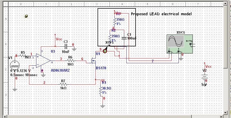
To do this, I thought about the exit a pulsed voltage AO0, sending voltage to a transconductance amplifier and generate a current in my care.
It is my transconductance amplifier... load, modeled on the square, is referred to as the + 5V on the PCI-6251 map and no 'field', since I need to be negative.
Now I have to read the voltage on the load through the AI0, and I lost between issues of land... Because the load is called my + 5V, should I measure differential or simple nerve?
Thanks for your time
Denise
Hi Denise,
You must acquire in differential mode.
See http://www.ni.com/pdf/manuals/371022k.pdf page 4-12
Ciao!
-
SMU-6363 pressure measurements
Hi guys,.
First post here. I tried to search first for documentation but empty is come.
I use the analog inputs on the 6363 map to make some measurements of voltage. I have 2 questions:
- I know that the channels are limited to +/-10 volts for entries. I have a 25 Volt with a resistance line series regular (50mOhm) sense. I want to do a differential measure resistance across with 2 analog channels. The real tension between the two points will be in the range of mV, but the unique finished voltageon each will be ~ 25 V. Will this work?
- In a similar configuration, but on a 5 volt line can I build a differential measure through a resistance of sense current using 2 channels and then turn around and use one of these same channels for a single measure is complete wrt gnd?
Thanks for your help!
There is a row in the datasheet that States
Maximum voltage of work for the analog inputs (signal + common mode)
±11 AI GND v So with a 25V common-mode voltage, you will hurt your card. The 5V line should be fine.
If you look at Digikey, there are chips specially designed to detect a current shunt. The differential voltage amplifiers will become a simple nerve from the ground.
-
I use a PXI-5105 card and trying to use the example called "niScope EX Differenital.vi". When I try to run the sample with the Terminal configuration to differential I get the following error
ERROR CODE:-1074135024
niScope launch Acquisition.vi:3
no valid value for the parameter or property. Device: Name of the channel of the OSC: 0 property: invalid value from Configuration Terminal: differentials possible values: simple nerve
State code:-200077
If using the example of the same value, but the single terminal condiguration ended, I get the above error. Don't know what I'm doing wrong. Any input would be greatly appreciated.
Thank you
Denise
Have you looked at the requirements when you opened the example? It is said the only 5922.
Like bench extended, the NOR-Scope is not a differential input setting. It is exactly what the message says. If you want to take a differential measurement, you must use two probes and subtract one from the other or use a differential probe extended.
-
How can you say [inputChan] = ' / Dev1 / ai0:7, Dev1 / ai16:23, / Dev1/ai32: "in LV 8.51
People-
Card PCI - 6225 DAQ a CBS, an expression of CSC block. Were released in a Mac G5 with routines c, but now need to move the DAQ card in a XP box and use LV 8.5.1. you will need to start a task for 2500 samples on 17 differential channels and prefers to use the DAQmx screws (I think) to change the number of samples, etc. programmatically, rather than tasks set Max or to express screws. Calendar clock sample, triggers, etc. are simple screws c, but I don't get the string formatting in DAQCreateVirtualChannel.vi for example.
Thank you
Alex
Why wait for 8 channels, see when you have 16 defined in the list of physical channels? I don't think you quite understand how channels are used in differential mode. Ai0 is paired with ai8, ai1 is paried with ai9, etc.. Specifying ai0 and differential mode, ai8 is automatically used. DO not specify - mode bonus entries and that you can NOT pair ai0 with ai16. If you use the differential mode of traditional DAQ or in another language, nothing is different with LabVIEW.
-
Synchronization of signals on my SBRIO problem
Hi all
I need some advice on how to complete my project.
I need to send a 32 bits of data to my unit test with the following parameters. CLK + FS + and +.
The clock runs at 4 MHZ. The FS + sends a bit length 33 of high for the treatment of the data signal, and in this context, I need to send my 32-bit data.
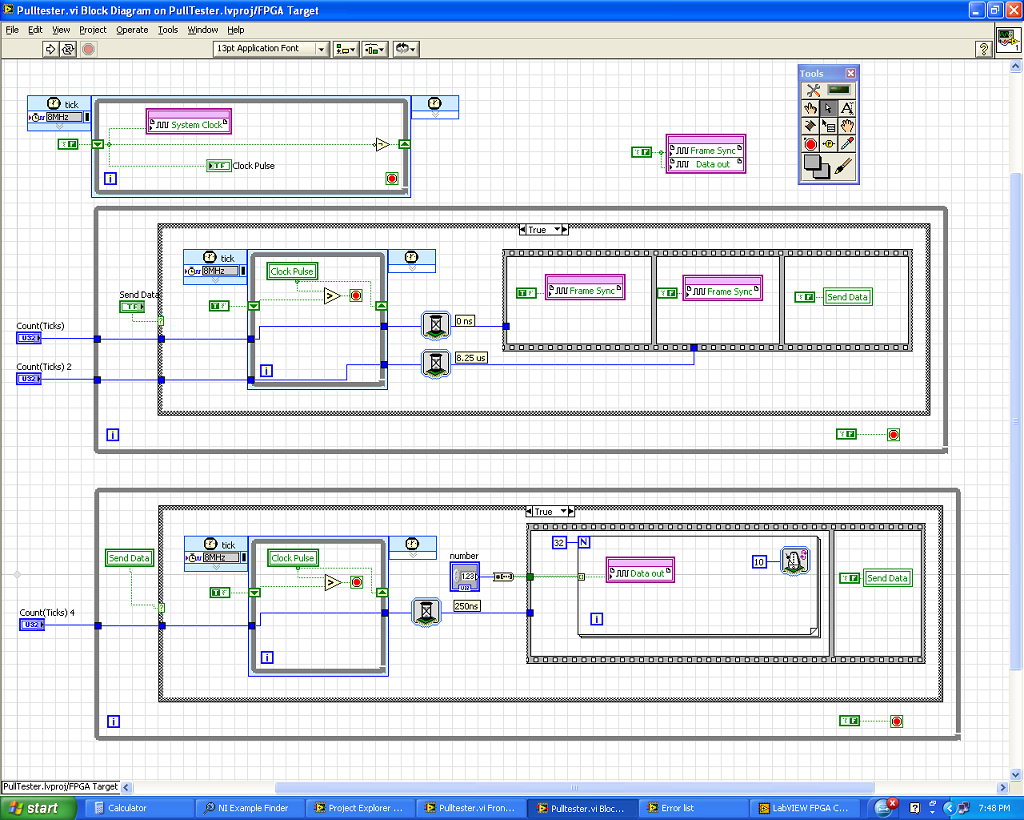
What I did is I created 3 loops as shown in my diagram.
1. the first loop is a loop timed to generate my clock pulses. I run at 8 MHZ with the low and high signals in loop rotation.
2. the second loop is for my frame sync signal using the rising edge of the clock over an external trigger (SEND DATA) to start the sequence. It has two red WAITING to the 0 graduation and 330 ticks (by tick is 25ns).
I have compiled up to this version of the code and run it with all the problems. I was able to generate the signal FS + 2ns after the clock rises and is to have cycles of clock exactly 33 in length.
3. the third loop which is I'll have trouble at this time is designed to loop data. I also used the pulse of the clock and the external data to start the sequence. I used one signal to WAITING to delay the start of the data by 1 clock cycle and use a loop for send data from 32-bit to 250ns (10 ticks) per line.
The problem is that I do not get the result I want. The departure of the bits is always erratic and not 1 clock cycle of delay that I hoped. Also the first bit is much too small for the 250ns.
Can someone tell me where I'm wrong? Is there another way to address the issue?
Your help will be greatly appreciated.
As a short response, I would recommend combining the three sets of loops in a single state machine. All three loops are intended to be based on the field of derivative 8 MHz clock.
As a longer answer and to explain the behavior you see... the time of the present code is assigned by the data through the areas of the clock. The details are in this help message LabVIEW FPGA: implementation of multiple clock domains with the overcoming of the areas of the clock (using a tunnel in the field to clock 8 MHz timed loop to the domain block diagram clock 40 MHz), LabVIEW is obliged to implement a hand shaking algorithm to maintain the integrity of the data. This shaky writing consumes FPGA (logic cells) tissue and takes 25ns several clock cycles to run, as well as creates unwanted delays. In addition, the third loop cannot guarantee that code data will trigger off the same synchronization signal as the second for loop because of the handshake that occurs for the data to pass through the loops of 8 MHz.
I would recommend that base you all of the communication out of a single loop timed in a configuration called a state machine. Essentially, timed with a looping structure business inside, where each picture of the structure of the case is a different State. Breast of a timed loop state machine, does not have the 'wait' function, so the delays must be implemented with a 'status quo' State which is repeated N number of times to match the time required. The following link leads to a state machine similar to the SPI communication that would be a good example for the implementation of this communication: Example of SPI LabVIEW FPGA.
The example above implemented the following communication scheme, which seems pretty close to what you implement:

This code is a little more complicated than what may be absolutely necessary to your application, but it is an excellent example of a scalable & flexible of the notion of core implementation (this code can easily be migrated to new hardware targets or add multiple replicated or modified communication to the same architecture protocols.)
See you soon,.
-
Premium vs potentiometer only finished reading
Hello
I want to read a potentiometer supplied with voltage the + 5V and GND signals from the DAQ card. I thought to connect output GND directly on the potentiometer and use single ended mode. Is there any point in using the differential mode in this case. If so, do I I just connect GND output directly to the entrance HAVE?
Thank you.
Simple nerve should work fine.
-AK2DM
Maybe you are looking for
-
I have four accounts open TB: mine, woman, club and spam. Only mine and spam account display the Recycle Bin icon. The other two accounts have a folder named "Trash". Deleted files go in the Trash files, is similarly in the trash icon files. However,
-
Firefox is not reading my profile restored after reinstalling Windows
I had to reinstall Windows (again!). Before that, I saved my profile on an external drive. I followed the instructions to restore (created a new profile and copy/paste the files saved in the new profile folder) and can see all the recorded files now
-
Hello. My 5s iPhone when I connected a mixer without merit on the head taken telephone and placed on a large metal fridge. The phone proceeded to get very hot, as more than 110-120 and then die. It doesn't or reload. I want to sell it, but I want to
-
Compaq presario s4100nx: how to clear data on the disc hard the one computer dead
my computer does not turn on more. no lights. It could be a power supply issue. lights at the front and rear lights for a second and then go off. It is not a new computer. I decided to recycle, but I would like to erase the data on the hard drive, be
-
Photosmart D110: Photosmart D110 don't wake up
My HP printer will not wake up to print from my computer. If I restart the printer, I can print from my laptop. I can get one or two impressions, but if I wait a while he won't wake the printer to print. The printer is connected to my wifi. Can I pri