Clock rates double d500
Why is a 725Mz and the other 150Mz?
Where are you looking?
What card has connected monitors?
Tags: Mac
Similar Questions
-
explain DAQmx WARNING 200035 conversion rates lower clock rate minimum?
I'm sampling of data at 1 kHz on 3 channels using DAQmx read. The DAQmx Read function returns a warning that:
"Specified clock rate is lower than the minimum conversion rate of the ADC." Your data may be invalid.
The material I have is a Multifunction PCI-6115 data acquisition of NOR. If I am interested in signal above 100 Hz can I safely ignore this warning or what I taste to 50 kHz and then have labview re - sample data at 1 kHz?
Hi, according to the specifications you are limited by a minimum of 20 kS/s sampling rate. anything weaker that should give you the same error, because this is a physical limitation of the card is using the internal sample clock.
-
Example rate vs clock rate cRIO
I try to get my head around the difference in sample rate vs clock rate in the cRIO so I can explain it correctly my engineers in optics.
I have a FPGA code that is just the Basic with e/s example. Modules 1, 2 and 3 are NOR-9201 with a sampling frequency of 2uSecs. The FPGA runs at 40 MHz or 25nSec/Cycle. Read in the documentation of the loop While takes at least 3 clock cycles. Estimate that other functions of the loop take about 7 clock cycles, the loop should run in 250nSec.
This is faster that the 9201 - can enjoy.
What does the FPGA? He expects the sample at the end? Takes the value of the previous sample? Do we get a partial sample?
Paul_Knight_Lockheed_Martin wrote:
He expects the sample at the end?
Yes - the loop runs in reality more slowly - he will meet at the level of the I/O node to the end of the sampling - time which is the sampling rate of any module is in the loop. For example, some modules analog high-resolution have read very slow time (like 52ms) then the loop will run at a rate of around 52ms (according to any other code you got in there).
If you have the e/s high-speed digital, you almost definitely want to put it in a different loop at any analogue I/O so it is not slowing down your loop.
I think that some modules are able to run in a single-cycle timed loop - in this case, the module will run in a single clock beat (for example 40 Mhz).
-
Using results of actual rate clock by error 'the specified resource is reserved.
Hello!
I use DAQmx 9.8, win10 x 64, NI 6221 emulated Council, labview 2012 32 bits.
I need to define the AO sample clock frequency, check the actual clock rate, calculation based on the new value of pulse rate and write it in the jury for the output. The code example is attached.
Everything is ok, when I use the command as a timing (as people used to do) during the installation of the task, but when I am trying to set the clock frequency, then number of samples I get "error-50103 that is reserved for the specified resource. The operation could not be performed as indicated. The error occurs after DAQmx Write.vi. I tried to use two calendar controls or a combination of timing and order property node timing with the same result.
Is that it has no idea how to solve this problem? Probably, there are some more convenient way to get real rates that I don't know.
I him have not tested yet on real hardware, emulated alone on board.
Finally, I dindn can't reveal the source of the prolem. It was certainly not related to the synchronisation screw. Just more simple configuration of analog output generated the same problem in this VI, but working without errors when copied to the new file.
Rewriting all of the project from zero contributed to y for remedy. Initially, I tried to change the existing program of someone else to change the generator stand-alone benchtop to DAC signal generation.
Now, everything's fine. Due to the software is not complicated it only takes a few hours to rewrite

-
Clocks on board and derivatives of FPGA
Hello
I use a PCIe FPGA 7852R card to collect data at 200 kHz of channel 5. I was pretty confident that my collection frequency was correct, because my program was based on a derived clock of 40 MHz I had chosen to use a derived clock because the on-board clock is running at 40,02 MHz (instead of the 40 MHz specified for some unknown reason I ignored).
However, today one of the members of the LabVIEW support team told me that the FPGA clock rate may change during the compilation and optimization (constraints). He stressed that if the FPGA can run that fast, then it displays an error (as you might expect). He said also that in some cases, the on-board clock can run faster, but in this case no error will be displayed. I saw no errors in the past (which means that the system had no problem with that fast running), however, I'm not sure if during one of my compilations my derived clock could have run faster than 40 MHz. If it can happen? This will affect the time of all of my previously acquired data. Unfortunately, I have not saved any of my journal compilation of
 .
.Thank you very much in advance.
Kind regards
Varun
Hi VarunSreenivasan,
I think that our support has meant that compile logs will show you some pieces of logic could operate at higher speeds. During the process of compilation, the compiler will determine the clock frequency more rapid that can be used for your logic and to ensure that the configured clock frequency is less than or equal to this value. If you have decided to try to run your code to 200 MHz and logic cannot run this fast, then you get an error. If you have decided to run your logic to 200 kHz and it is possible to run faster compilation logs will show you then the max frequency that will work, but the logic still run to 200 kHz. The code should run no faster than the frequency you specified.
-
How to increase data FPGA clock?
I use LV 14 and 14.5 USRP. When I plug my new USRP-2940R-120 and run a program written for a USRP-2940R-40, the driver gives me a message that says "you are using a bitfile configured for data clock which is slower than the rate required for the bandwidth of this device. Risk of aliasing in your signal. "(error 1073383043).
Fair enough.
Then I looked at the data of properties of the clock in the application project and that I could not change the values in there. Then... How can I change the data FPGA clock frequency and what do I change to?
Thank you.
Hi emonk,
We have created a new FPGA target what samples at 200 MECH. / s to use the increased BW. You need to recompile your application using the new target. My recommendation on the best way to proceed is as follows:
1 generate a new project of the sample. With NEITHER-USRP 14.5 all the projects in the sample have now both targets (120 MPS and 200 projects of average size)
2. don't customize you the FPGA in your application? What if not all you have to do is use the bitfile for the target of 200 MECH. / s of the project in your host code example. If you did, you will have to redo these customizations in the FPGA VI of high level of the target. It can be trival or difficult depending on your application,.
3. you will then need to recompile. Because of the faster clock rate, the meeting schedule is more difficult, your FPGA IP may need to be optimized if you work in the field of data clock. I suggest that the kickoff from 5-10 compile at first because of the variabiliy in each compilation. If all still fails, use the timing to study reports where optimizations are needed.
I would like to know if you have any questions or encounter any problems.
-
cDAQ HAVE task using external clock
Hi, I am trying to use a clock signal on a line of PFI in order to generate a clock, but at a lower rate, for a task to HAVE. I run into many issues that I can't explain.
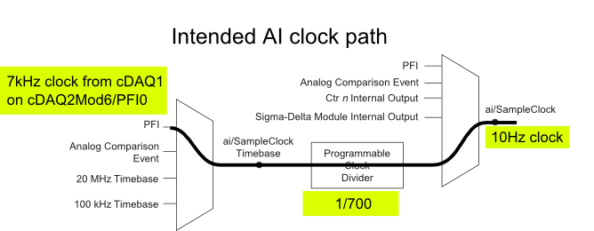
I have a cDAQ-9172 with an entrance module analog (9225) in the Groove 3 and a digital input module (9411 - 2 MHz DI) into the slot 6 (where the PFI lines are accessible). I want to use an external signal on et0/PFI0 to act as the clock for an analog input on the 9225 task. This signal comes from the cDAQ anothr chassis and is too fast for the task to HAVE it, so I intend to use the time base entrance and the divider to clock (as shown on page 31 of the cDAQ-9172 manual). See picture attached for a graphical representation of my problem.
If I have the wiring from the signal "/ cDAQ2Mod6/PFI0" in the DAQmx timing VI, get the error 200414 saying that "required sample clock source is not valid." It is strange because it is listed as "Direct route" in Max (the VI of polymorphic DAQmx Timing is configured as 'Sample clock') Q: why this route is not suitable for the task?
If I use DAQmx Timing property node and change the Source 'Sample clock Timebase' to ' / cDAQ2Mod6/PFI0 ", the task starts without error, but the separation seems to be forced to 256. If I try to change the properties of the separation of the time base, I get error-201100. Try to change the 'sample clock rate"doesn't have any impact on the task and the remains of divider"256 ". Q: why the 'Programmable clock divider"locked to 256 when using the PFI line or can you just not program directly?
I came across another error is the minimum speed on the PFI line. If I have the wiring (for the SamplClock Timebase) lower at 1 MHz, LabVIEW returns error-200077. The error message indicates that the minimum value is 1 MHz. 9172 manual shows the clock 100 kHz is an option for the time base, certainly less than 1 MHz. Q: What are the limits of upper and lower frequency for a clock signal on the line PFI for the ' Timebase AI/SampleClock "?
I looked on the site and in the DAQmx documentation for further explanation, but I have been unable to explain these strange behaviors. What are the barriers to entry of Timebase PFI and the time base "Programmable clock divider" preventing me to reach my goal here? If I can't do it directly, can I use the PFIn signal to feed an internal counter (to act as the clock divider) which could then generate the clock WAS at the rate I want? This method would allow me to perform a division arbitrary clock (unlike the ' 256', which seems to be forced on the PFI as a Timebase SampleClock.)
Finally, something seems odd that I can make an acquisition to 10Sa/s max but when I start a task using an internal timers of the cDAQ9172 and ask a 10Sa/s rate, the task really gives me a rate of 1612.9 sample/s while using the 12.8 MHz clock and a divider 7936 timebase. Q: Why can't the task to 10Sa/s?
I use DAQmx 9.7.0 and LV2012 SP1 (and I tried with 9.7.5 but I got the same results)
Thank you
Olivier
I got additional help Friday in another engineer at NEITHER and the solution to my original problem is actually very simple to get the clock from an external source path:
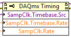
The idea of picking a PFI line for the basis of 'time' and the 'Programmable clock divider"(in fact, DAQmx calculate this number based on"HAVE sample time clock"and"Sample clock HAVE") works by using the node property below:
(SampleClock.Source cannot be resolved until the task is clerks/reserved, but the default option seems to be the time base that works well in this case.)
The question that I described earlier with the 9225 comes the module properties and the fact that it is a "Module of Sigma - Delta". That the module usually generates its own time of 12.8 MHz base clock (page 14 of the document 9225 # 374707) and the clock divisor is much less possible values than the other modules (must be a multiple of 256). It may use a different time basis from a PFI line, but it must be between 1 MHz and 13.15 MHz.
So a main clock between two chassis and tasks running at different rates of sharing should be easy and simple with most of the modules. With AI modules with Sigma-Delta converters add additional limitations and the master clock for the time base frequency must be selected to accommodate these module as well.
Another good news is that the Simulator seems to bear all these details and DAQmx (9.7.0 in my case) generates the same errors when you use a simulated chassis if you use real body. Play well!
-
Nor-6120 - sample real resolution rate
Hello.
I use the card OR-6120 and labview 8.2.
And I have not found information on the resolution of sampling rate.
So I wonder if anyone knows what is the resolution?
And I can get the real value of the sampling frequency of the card once I programmed the sampling frequency that I want.
Thank you!
Sincerely,
Roman
Hi Roman,.
Referring to the technical details of the frequency of sampling for a PCI/PXI-6120 is 800 kech. / s with NOR-DAQmx divers.
If you want to get the actual sampling frequency with LabView and DAQmx drivers use a Calendar property node and select sample clock > rate.
Kind regards
Ludovic R.
Links:
-
Hi ppl,
I have a question for you.
I have a very similar to the attached picture circuit. also you can find here (http://zone.ni.com/devzone/cda/tut/p/id/3615#toc4 , fig.2) I write some data on analog channels out and then I collect the data in the time loop. I don't understand what exactly is happening when I write the data in the buffer. Let's say I have a table of 2D 2-lines and 62500 columns that I want to write in the output analog channel, then read in the analog channel. I do not understand the meaning of the sample clock. (I read on operations 2 devices simultaneously and blah blah blah). What should be the sample clock frequency in the August channel and the channel of the ain and the number of samples per channel in the ain daqmx channel when I want to collect data? (http://zone.ni.com/devzone/cda/tut/p/id/2835; reading the data in example labview). My problem is that I do not understand what is happening when I load the August channel with data buffer; for example I put the sampling clock rate: 1000; meaning he will write each s 1000 samples of 62500 samples until the end of the samples; all of these samples that I drove from my out channel voltage piezo-beam-scanning engines. which means that each s piezo motors will get 1000 samples of tensions? now, I want to measure. should number of samples in the playback channel I put? I put my daqmx reading in the while loop. Let's say I put 100 Samper useful/channel. so, each itteration in while loop it will read the 1000 samples/channel buffer. How will I know that the buffer is already full with 1000 samples when ain channel tries to read?
The process is therefore more; correct me please if I'm wrong. The sample clock will define us the buffer data rate. For example, I load the 2D matrix: 62500 2rows columns; It will load in the buffer and then there are these samples at the August channel of the rate defined in the clock sample string? Then I want to read from the channel of the ain. What sampling clock frequency should I set for the channel of the ain? If the sample clock rate for the playback channel sets the buffer? for example (I put it there 1000 samples/s; meaning it can read 1000 samples per second?) then what the number of samples should be in the read daqmx channel in the while loop?
Please clarify me this point, I'm confused...
Hi dimani4,
There is a very comprehensive document that answers your questions. You can find this document here.
This article explains the operation of the sample clock frequency and the DAQmx Read reading samples. Quoting the article: "On the hardware side, the Schedule VI DAQmx determines the flow rate of the device/sensor data at the hardware buffer on the data acquisition card.". Here is the 'Timing VI' the sample clock. Then he also explained that "on the software side, the reading VI DAQmx determines the transfer of the data of the buffer material in the software". "." It is making reference to the samples to read the reading VI DAQmx.
I hope this information specific to your questions.
-
I want to integrate the ANSI C sample program ReadDigPort - ExtClk.c in my own big package.
I want to use the internal clock of the BNC NI USB-6259 (.. 80 kHz 120 kHz).
In the document:
High speed M: Series Multifunction DAQ for USB - 16-bit, up to 1.25 MECH built-in BNC connectivity. / s,.
is written:
Or sample DI source clock: Any PFI, RTSI, HAVE sample or convert clock, AO, Ctr n out internal and many other signals sample clock
The digital subsystem doesn't have its own dedicated internal synchronization engine. Therefore, a sample clock must be provided another subsystem on the device or from an external source.How can I use internal clock case OR USB - 6259 BNC for the acquisition of digital data in my own big software?
With what other subsystem on the device can generate a source of the clock? How?It is possible to set a clock on an internal counter (for example ' Dev1/ctr0"):
Creates channels to generate digital impulses that define the freq and dutyCycle and adds the channel of the task that you specify with taskHandle.
DAQmxCreateCOPulseChanFreq (taskHandle, "Dev1/ctr0" units, clockName, idleState,
initialDelay, freq, the duty cycle); worksBut it is not possible to drive this internal clock to a terminal (for example "/ PFI0/Dev1"):
DAQmxErrChk (DAQmxCreateCOPulseChanFreq (taskHandle, "/ PFI0/Dev1", clockName, units, idleState, '))
initialDelay, freq, the duty cycle); does not work: error DAQmx: measurements: type I/O of the physical channel does not match the type of I/O required for the virtual channel you create. Name of the physical channel: PFI0. Name of the virtual channel: clockThe sample clock source can be derived from an external terminal (for example "/ PFI0/Dev1"):
Sets the source of the sample clock, the sample clock rate and the number of samples to acquire or generate.
DAQmxCfgSampClkTiming (taskHandle, "/ PFI0/Dev1", maximumExpectedSamplingRate, DAQmx_Val_Rising, ")
DAQmx_Val_ContSamps, bufferSize); works. Acquire or generate samples until you stop the taskBut it is not possible to derive the internal counter of the clock (for example ' Dev1/ctr0"):
DAQmxCfgSampClkTiming (taskHandle, "Dev1/ctr0", maximumExpectedSamplingRate, DAQmx_Val_Rising,
DAQmx_Val_ContSamps, bufferSize); does not work. Error: Acquire or generate samples until you stop the task: make sure that the name of the terminal is valid for the specified device. See Measurement & Automation explore valid names of terminals. Property: Property of DAQmx_SampClk_Src: DAQmx_SampClk_ActiveEdgeSource device: Terminal Source Dev1: Dev1/ctr0Hi datafriend,
using what it says is correct:
Or sample DI source clock: Any PFI, RTSI, HAVE sample or convert clock, AO, Ctr n out internal and many other signals sample clock
The digital subsystem doesn't have its own dedicated internal synchronization engine. Therefore, a sample clock must be provided another subsystem on the device or from an external source.This means that if you do not use an external signal as clock you can use the sample clock to HAVE it on board or at the output of the internal counter.
There are also 2 ANSI C examples in this regard:
http://zone.NI.com/DevZone/CDA/EPD/p/ID/4485
http://zone.NI.com/DevZone/CDA/EPD/p/ID/4488
So in both cases you have to use a fictitious task you need only for the generation of the internal clock (HAVE or CTR)
-
NI 5122 range Variable sampling rate
Hello
I use a digitizer card high-speed NI 5122 to acquire data and synchronize the sampling frequency of the frequency of the data card. For example, my first set of data will have a frequency of 13.6 MHz so I would taste 13.6 MHz. When I connect a signal 13.6 MHz to the CLK IN on the front panel of the card and write Labview code to taste at this rate (for the sample clock or reference clock), I get error message. Anyone know if its possible to have a sampling rate variable really for this card?
Thank you
Steve
Hi Steve,.
I understand that you are using a digitizer high-speed 5122 and try to use an external sample clock. What kind of error messages received when you doing? In addition, how you set up the device to use this external clock?
"" "" I would also like to point out that there is a very useful example program in the example Finder LabVIEW ('Help' to find examples) found in e/s material "Modular Instruments ' OR-SCOPE" features ""niScope Clocking.vi external EX' that allows the user to make a simple acquisition using an external clock source. To specify the source of external clock, rate and divisor, a knot of niScope property is used. You should be able to try this example and use the same method in your program. Hope this helps,
-
Clock tick slow, erratic in Windows guest OS
I have two problems that significantly affect my use of VMWare. I am running Workstation ACE edition v6.0.5 - 109488
hosted on an HP system with plug Dual Core AMD Athlon 64 X 2 5600 + 2,81 ghz 2.87 gb ram. The host operating system is XP pro x 64 SP2 v2003.
I have a number of virtual machines on this x 64 system and they all have problems, I will describe and I have similar VMs on two
other systems, an XP pro SP2 on a 32-bit laptop and W2k system, also 32-bit and these virtual machines do NOT have these problems.
The problems are:
(1) to start the computer virtual, for a period of several minutes, just type in the VM (caps startmenu, passwords, back/netware guests)
is repeated one or more times. Meaning if I have an XP virtual machine and the password of the connection box is open and I type a character which
character is repeated one or more times, usually 5 to 10 times. It is essentially impossible to type until the problem
clears up on its own, it does after letting the VM sit for about 5 minutes.
(2) all the virtual machines on this x 64 exhibit erratic clock tick as the host. Tick its second click of observation with the windows date cmdlet
clock hand and also other applications that display the second time, I see the second count occur very quickly (i.e.
faster than one per second) and also very slowly (a second socket to 4 seconds of wall). As I have what I can observe
See counting the seconds speed upward, slowly down, sometimes appear normal (although normal never lasts very long).
I see this on all my virtual machines (NT, XP, XP, Vista, netware), but they all perform more or less acceptable than the second count. However
my Vista VMs are dog slow and my test season a relationship between the slow clock and poor performance. A Windows 2008 VM shows a slow clock, but the beat of clock rate does not vary and is acceptable error. Virtual machines are configured to run on a single processor.
Note that I usually run 3 VMs at the same time. A novell VM server, a windows NT4 VM and a test VM, which is generally
XP or vista. The novell and NT4 VMs host print services and email and are usually do nothing but idle.
I studied this problem of clock and found all sorts of news and changes of parameters in config.ini and .vmx file, but
None of these things has made an observable difference.
I remember reading about an AMD Dual Core Optimizer utility that allows to synchronize the time between carrots stamp counters. Maybe this will help? Visit the website of AMD...
-
Pavilion dv7t - 6 c 00: RAM upgrade will BSOD
I bought this computer a few years knowing at the time that I could have upgraded to 16 GB of RAM. Yesterday, I replaced a hard drive in another HP with anticipation of upgrading the RAM, only to discover that it was already contributed the most. I see nothing for mine that says I would have problems (chipset, proc, ram speed, etc.). I had some PNY sodimm ddr3-10666. I know it's a superior to 10600 clock speed, which is what came installed, but everything I read (including the packaging that the new ram came) States, the system will be just to the low clock at 1333 mhz. I got about 2 hours of use today before a BSOD, so I stopped and considered as to remove the new RAM. I swapped the sticks in the measure of the placement of mobo (I can't find anything that says it's really important for this model), but still have the same question. I can sit on the login screen of windows, but as soon as I connect and start something, I get another BSOD. Is there something I forgot, or the system hate this memory?
It's the memory that you want; That is to say a pair of these 8 GB modules for a total of 16 concerts:
Module memory 8 GB for use only with the computer models equipped with an Intel processor (10600, DDR3 1333 MHz) 634091-001
Mr. Kingston, it's selling as a compatible module:
It is the memory low density of 1.5 volt. You can link us to the specifications of the memory you have installed? I saw also known as PC3-10600 and sometimes PC3-10666 DDR3. Memory speed is indicated two ways... the DDR3-1333 says it runs at 1333 'calls' per second or data rate double to 667 "turns" or cycles per second. PC3-10600 talking bandwidth... how much data can pass through per second.
So yes, it is I suppose that you have installed incompatible memory. It is not as easy as before.
-
Best way to generate signals of activation (square wave) with my 9401 on my 9022?
Hi, I tried seriously over the past two days to find the best way to do it. I am trying to generate a very precise square wave, controlling the duty cycle and frequency, with the OID on the 9401 in testbed cRIO 9022.
I have a VI that is theoretically able to do this, but whenever I try to go above 5 Hz or more, duty cycle and frequency becomes inaccurate (I have watch on an oscilloscope), various a lot too for my needs. I have a feeling that this is caused by my addiction on the calendar software controlled, with errors at the time (of the ms order) accumulate as they get processed and the signal is sent. I have attached a piece of code that illustrates the basic idea of what my VI have in them.
I have avoided the square wave generators integrated because I could never work to satisfaction, but I can work with them so that will solve my problems. Selection structures and cases prevent the user to exaggerate their inputs. Unwaited so the loop was just to test.
I'm running the 9022 as target in real time, but also tried to run in the FPGA and I was able to produce much more accurate signals using FPGA VI square wave, displaying a Boolean variable, but I couldn't see the best way to get double precision variables to work with everything (and I want more precision than variables FXP enabled clock 40 MHz).
I feel there is just a mistake in my approach here. I've seen other discussions where people throw around using meters to edge of the test bench to produce a square wave, and I see the example screws as Gen dig pulse - continuous Train, I'm not sure if initially these screws DAQmx for my situation (eg. How to identify my counters, because they are clearly not Dev1/ctr0 by default in these examples)
Thank you
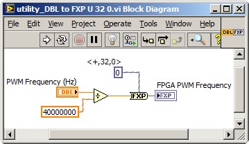
Dealing with the representation of Point fixed and all is a reality for LabVIEW FPGA<= 2011="" programmers.="" you="" might="" build="" a="" small="" sub="" vi,="" such="" as="" the="" one="" attached,="" to="" encapsulate="" the="" frequency="" calculation,="" thereby="" abstracting="" the="" conversion="" formula="" and="" fixed="" point="" data="" type.="" you="" can="" adjust="" the="" properties="" of="" the="" floating="" point="" input="" control="" to="" accept="" only="" valid="">
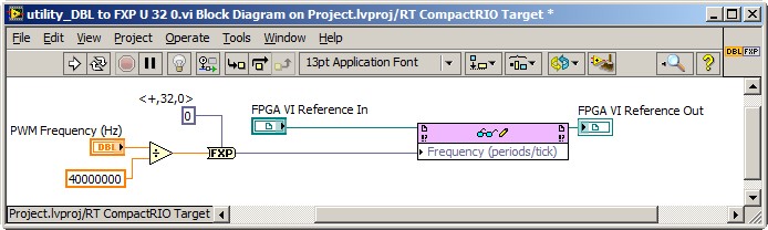
This implies the series VI void on the host of the RT, and not on the FPGA target. So, you also need nodes in the Palette of the FPGA Interface to send PWM fixed Point RT frequency to the FPGA. The complete solution of frequency may resemble the following. It is common for FPGA programmers to build a collection of thesesub screw, that make up the API for hardware.
Note that 40 MHz is hard-coded. For increased flexibility, consider making the FPGA clock rate an entry to the Subvi with a default value of 40 MHz.
-Steve
-
LabWindows CVI RS-232 is not fast enough
Hello
Is it possible to write a C program which takes RS-232 data buffers and prints it on the screen?
I ask this question because I write a program in LabWindows CVI and the data is not correct. I used SimpleTerm Gold to see what data are supposed to look like, but CVI misses some. I believe it is not fast enough and therefore lack of data.
A C program (do not use the functions or reminders CVI) would be possible and better?
Is it possible to make the CVI to work faster? I changed the environmental policy of the previous "do not sleep". There are two ComRdTerm because we're not getting all the other packages.
Rate 115200 baud, no parity, 8 data bits and 1 stop bit. Most of the data I receive are 313 bytes and the smallest is 17.
Any help would be MUCH appreciated as I am completely puzzled.
Thank youCode is below.
OpenComConfig (com, "COM9", 115 200 Baud, 8, 1, 0, 1024, 1024); / /< opens="" serial="" ports="">
SetComTime (com, 0); / /< sets="" serial="" port="" to="" never="" time="" out="">
T0 = clock(); / /< calculate="" how="" fast="" comrdterm="" is="">
bytes_read0 = ComRdTerm (com, & buffer0 [0], 314, 10); / / read com and store it in the buffer
sprintf (p_check0,"%.4s" & buffer0 [0]);
T0 = clock() - t0;
Double time_taken0 = ((double) t0) / CLOCKS_PER_SEC; / / in seconds
printf("%d\t%f\t%s\n",bytes_read0,time_taken0,&buffer0[0]);
Memset (buffer0, 0, strlen (buffer0)); / / Clears the bufferT1 = clock();
bytes_read1 = ComRdTerm (com, & buf1 [0], 314, 10);
sprintf (p_check1,"%.4s" & buffer1 [0]);
T1 = clock() - t1;
Double time_taken1 = ((double) t1) / CLOCKS_PER_SEC;
printf("%d\t%f\t%s\n",bytes_read1,time_taken1,&Buffer1[0]);
Memset (buf1, 0, strlen (buffer1));Thanks for all the help guys. I finally found the solution. The program was running too slow because I kept opening and configure ports (not shown in the code) I simply kept open ports and it works fine.
I appreciate all the comments and insight. Each of them will definitely help me still to develop with CVI.
Kind regards
Keegan.R
Maybe you are looking for
-
Why is it not compatible with Mozilla Firefox 5 Download Accelerator Plus?
I've updated current Firefox and DAP in their respective version only to realize that the Firefox 5 is not compatible with 9.6 DAP. However, previous versions of the two were compatible with each other.
-
Satisfied by Epox BT BT-DG06B and Satellite M70-144
Hello! I bought the Epox bluetooth dongle. It also manages the bluetooth version 2.0 and 30 metres range.I use it via battery Microsoft BT who was already installed by default on my laptop Satellite m70-144. I think that my BT is not compatible with
-
to install hp photosmart 3210 on laptop with vista
I have a HP Photosmart 3210 printer installed on my home network. He was running from my old PC. Now want to link my laptop that runs Vista and can not install the printer. Any ideas how I can get around this? Thanks in advance.
-
sx280hs screen black vertical while
When I try the camera vertically the screen goes black (in any one direction vertical rotation). When it is horizontal, it is fine. It will take a vertical photo, but I have no way to see which is the image as the screen is dark. How to solve this?
-
How to connect computer mobile printer
I have a laptop HP Envy 14, running Windows 7, a 64-bit system that I want to connect to my local printer (at home). It's a Dell 946 AIO printer. Although 7 people say they found one, I was unable to find a compatible driver. When I connect my laptop