compactDAQ sample rate question...
OK, I think I have a question in the right place, but if not I have forgiveness. :-)
I have a CompactDAQ (4slot) with just a 9225 and 9239 modules installed. I've run the DAQ assistant and have all seven current channels of reading and writing in a text file of a structure of event... when I push the button, it saves the data. Quite simple really, I have also a timer Setup 'Wait' with a 50mS wait time, so I'm basically updateing my loop 20 times per second, not so fast. The strange thing is that my DAQ module is only send me data once per second. A I put something wrong? Seems to me that as updates of loop, it should return 'true' the key to the structure of the event and the data should appear at a rate of about 20 samples per second. VI attached sample.
Tips and points in the right direction are greatly appreciated!
Chad
Hi chuggins143,
The behavior comes from your settings in the DAQ Assistant:
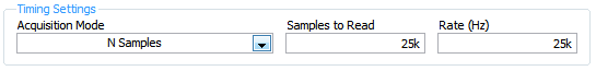
If you want the loop to run 20 x per second, then 'Samples to Read' should be 1/20 of the sampling frequency. DAQmx hangs until the samples 'Samples to Read' became available, so it's slowing down your loop. You can also change the Timing settings to 'Continue', if you want to avoid gaps in your data.
Best regards
Tags: NI Hardware
Similar Questions
-
fast sampling rate question...
Hello
I use USB-6009 and max sampling rate is about 48 K samples/s according to
the specification...
Question 1.
48 K samples/s means... only when you receive 1 analog input?
If I have 2 analog inputs then forge would be just half of the 48K?
Question 2.
using the daq assistant.
I would like to get about 50 samples between 10ms
If I do the math I get 5 K samples/s, which is enough for me
However, I played with samples to read and throughout the day, the sampling rate,
do not get this rate... (I'm outputing in file with LVM)
I searched on the sampling frequency, and people here said
samples read and sample rate do not havea correlation...
but I see clearly that they are relevant. When I change a setting
I get a different number of acquisition... I do N smaples.
Please help:)
Q1. Yes, except that the switching of channels takes awhile so the net price per channel is slightly less than half the rate of single channel. The USB-6009 specification document does not indicate what is the switching time. You should be able to get 5 kHz on both channels. 20 kHz might be close to the upper limit, but that's just a guess.
Q2. The DAQ Assistant is often not the best choice for maximum performance. I do not have the DAQ Assistant, so I can't be more specific. If you get the data as an array of DBL, rather than dynamic data type, it can be recorded directly, without conversion. The other thing that can make a big difference is a loop two architecture of producer/consumer. This allows the acquisition of data and save it to the file to run it at different speeds so that each can be optimized separately. If you are trying to acquire 50 ms of data at a time and then, he writes to the file, you write to the file twenty times per second. The first time, the operating system must reallocate some file space or do something else what delays write the file, your timing loop is disrupted.
Lynn
-
On the NI PCI-6221 fast sampling rate question
Hi I was wondering if someone can answer a question of sampling rate on this card to PCI-6221 (http://sine.ni.com/nips/cds/view/p/lang/en/nid/14132).
Especially if I wanted to transmit simultaneously (analog output) and data acquisition (analog input), what is the sample rate max I could use. Kind regards.
Since the 6221 is multiplexing the analog input, your question for I / simultaneous ao is possible for one channel of the only. If your "simlutaneously" can include delays (e.g., 100us), you may be able to work with several AI channels as well...
HAVE the multiplexes, workable sample rate given that the total sample (250 kHz) frequency divided by the number of channels that you use. AO is faster than HAVE it, so it does not reduce this number.
hope this helps,
Norbert
-
Hello
I tried to understand how the 'number of samples' and 'rate' controls affect the frequency of sampling for the DAQ hardware. For example, say I want to acquire data from a sensor of pressure at a frequency of 10 Hz intuitively, I would think everything I do is on the desired sampling frequency, in this case 10 Hz control the 'frequency', try this, I know that's not true. I read that 'number of samples' affects the sample rate by setting a buffer value that must be reached before the VI will process the acquired data. So I also tried to set the "number of samples" to 1 and "rate" at 10, thinking this would have led to a sampling frequency of 10 Hz, and again, it is not. The only way I know to control the sampling frequency is using the wait function (ms), but then I always get buffer overflow errors.
Can somone if you please explain to me the error in my thought process and also tell me the best way to control the sampling frequency? Is attached a simple VI, I am using to measure my actual sample rate and compare it to the sampling frequency that I am trying to achieve.
The VI use the DAQ assistant to acquire data of pressure, inserts data into a table, and measure the size of the array. I'm then by dividing the size of the array by the elapsed time in seconds for the sample/s (I'm also dividing the number of iterations of the loop by seconds and using it as a comparison). I compare this value to my entries for the 'number of samples' and controls 'speed' in order to give a sense of the role they play in sampling rate. The VI also allows to choose to use the wait function (ms), as well, using this function is the only way I can control the actual sampling frequency, but then I always get buffer overflow errors. Any information would be helpful, thanks!
What is the device that you are using? My guess is that whatever you have, it does not allow such a slow pace and is failing at its minimum.
-
Hello
I'm looking at possible solutions for data acquisition. I use 4 or 5 entries analog and two digital inputs. During the analogue entered most of them will not need sampling extremely quick rate except for one who needs the least 100ks/s. I noticed solutions cost-effective have overalls sampling rate (eg. 250 ksps / s) which extends on all channels. For these products, such that the NOR-9205 compactRIO module, is possible to distribute unevenly sampling rate between channels (ie. could I give up 100ks/s for a single channel and spread the 150ks/s rest between the remaining channels in use)? Thanks in advance for any help,
Adam
Hello Adam,.
To answer your question on the sharing of the sampling rate, it is not possible to have a single module different sampling frequencies, as described in this KB: here (http://forums.ni.com/t5/Multifunction-DAQ/Aggregate-sampling-rate-and-Multichannel-Scanning-Rate/td-....)
In the case of the 9205 this module multiplexes between all channels (32 cases set up in single ended mode or 16 in differential) this means that the sampling rate of 250 kech. / s matches total on all channels.
If you are using the differential mode then the samples per second on each channel will be 250 kech. / s divided by 16, IE 15KS/sec. However if you only specify 4 channels max sampling frequency will be 250 kech. / s divided by 4, IE 62.5 kech. / s.
One way around this is to use 2 x 9205 in one of our new CompactDAQ chassis, which has 3 engines of timing to HAVE. This allows to set different timings in 3 different modules. What is described in this KB: here (http://digital.ni.com/public.nsf/allkb/E7036C1870F6605686257528007F7A72)
I'm sorry of this reply took so long, and I hope the above information helps.
Please do not hesitate to answer questions.
If you want I could get one of our technical sales engineers to give you a call to discuss further with you data acquisition system?
Kind regards
-
So maybe this is a stupid question, but I need to know because I train for a specific sound. Is there a way [to logic] to shoot/change of a certain frequency sampling rates. I can imitate the sound I'm looking for with a low pass filter, reverb and a distortion. But I don't want to 'emulate', this sound, I want to create. Then I can put my own effects and play with it like I want to. If I have to use a bunch of effects to make it sound like I want that also the addition of said effects remove the sound and sound horrible. as to where pulling the sampling frequency of the high frequency and no downs will make me THE noise that I need and always allow to add nice effects to make MY sound instead of someone else. I hope you know what I mean. Let me to you specific real once more. I want to pull or carry a certain frequency sampling rates for a sound under water. I don't want to use filters to make the sound. So can you please help me. I invited everyone locally on how to do it and nothing works. Also if this is not possible in the logic of tell me if there are third party plug ins or maybe even a different DAW that could do like komplete Kontrol or audacity.
See if this thread is helpful at all...
-
I'm new to myRIO and use it to measure sine wave (0V to 5V) of up to 10 Hz 20 KHz. I also quickly transformed of Fourier (FFT) of the signal measured in real time.
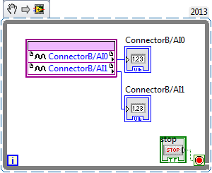
Sideways FPGA of things, I try to keep things pretty simple, just read 2 channels of AI (connector B: AI0 and AI1), therefore potentially able to read each HAVE 250 kech. / s (as the unit has a capacity of 500kS/s). Does that mean this program gets a two analog inputs data exactly every 4 microsecond? If this is not the case, how can I make sure that the data is acquired through a fixed sampling rate?
I realized that we can add to the FFT in FPGA function, but I wanted to manipulte the acquired data of analog inputs before it is sent to the FFT, which I don't know how to do now. Can someone explain me how do the arithmetic data (muliplication, division and so) on the acquired data and analog inputs to reducde the 12-bit resolution 10-bit to program FPGAS.
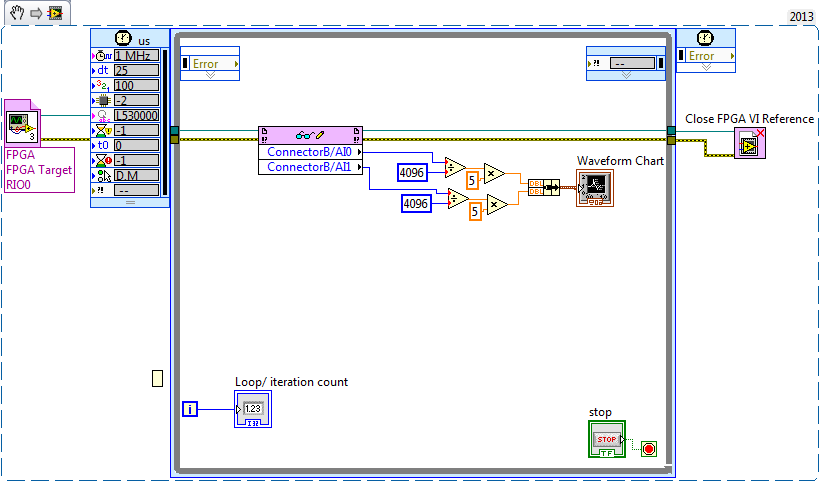
Later, I created a myRIO program to read analog data 2 FPGA program which continues to turn in timed loop. In the program myRIO, the timed loop is configured to 1 MHz clock source type by a delay of 25 microseconds.
This configuration means that the loop runs exactly every 25 microsecond?
When I set up the less than 10 micro second time, myRIO has stopped working. Why is it so?
Is it because myRIO cannot run as fast as FPGA?
It is advisable to make the FFT of myRIO side analog data or FPGA?
When I tried to do FFT using the power spectrum of myRIO side, he asked for waveform data. What I acquire is data analog. How can I convert in waveform data?
If I read in the forum for help, I couldn't have the full answer to my doubts
Discussions at the Forum I did reference:
A lot of good questions here, I will try to answer as much as I can so as to offer a bit of advice.
First of all, if you are looking to acquire data at a very specific rate on the FPGA, you'll want to use the Timer VI. You are also going to use a FIFO of DMA to transfer data of FPGA in real time. A node read-write using as you do now means you'll run out of samples, or read the sample even several times. The link below is a very good tutorial on how to do what I described above.
http://www.NI.com/Tutorial/4534/en/
Later, I created a myRIO program to read analog data 2 FPGA program which continues to turn in timed loop. In the program myRIO, the timed loop is configured to 1 MHz clock source type by a delay of 25 microseconds.
This configuration means that the loop runs exactly every 25 microsecond?
When I set up the less than 10 micro second time, myRIO has stopped working. Why is it so?
Is it because myRIO cannot run as fast as FPGA?
In general, you should not run a timed loop much faster than 1 kHz. Using timed inside loop knots, you can monitor the real rate of loop during execution to see if f you meet your needs of the moment.
The portion of your myRIO RT is slower than an FPGA in the sense where it cannot manage the rates of lines 40 MHz (he makes up for it by being able to work with much better pictures) and it is important to remember that it is just a computer. The advantage of a real-time operating system, is that you have more control on the Scheduler, not that he is faster (less jitter, not faster code). There is more good reading below.
http://www.NI.com/white-paper/3938/en/
It is advisable to make the FFT of myRIO side analog data or FPGA?
When I tried to do FFT using the power spectrum of myRIO side, he asked for waveform data. What I acquire is data analog. How can I convert in waveform data?
I would say that it is generally advisable to treat your FFT on the side FPGA as long as you have the resources available, but for many applications probably little matter ultimately.
-
DMM (NI 4070), how to correctly set AC Freq (bandwidth) by the sampling rate
using a NI4070 multimeter and I see the max connection is 300 kHz by respect it. But I don't understand how to set the min and max, acFrequency according to the sampling frequency or speed reading.
6 1/2 digits resolution, the speed can vary from 0.25 s/s to 100 s/s and this range corresponds to a lower end on the connection (minimum acFreq) from 1 Hz to 400 Hz.
(Q1a) - is the playback speed, controlled by the minimum setting of IviDmm_ConfigureACBandwidth? or vice versa?
Otherwise, I do not see how to control the rate of reading or the sampling frequency. IviDmm_ConfigureMeasurement only allows you to control the range and resolution.
(Q1b) - is there a way to directly control the sample rate (digitizer) or playback speed (dmm)?
(T2) - the upper limit of the bandwidth of AC always seems to be at 300 kHz... is there still a reason to reduce this maximum value?
(T3) - Finally, unlike the traditional niDmm function, the resolution via the IVI configuration should be passed as absolute value; does directly when number of digits and the beach? For example if I want to 6 1/2 digit to 300V range, I guess that by the specifications that the resolution should be set at 0.001 V... followign, if I want 5 1/2 digits to 1V range, the resolution should be set to 0.00001 V?
Hi Rjohnson,
I'll try to answer your questions as best as I can:
Q1A. The ConfigurACBandwidth function is used by the driver OR DMM to calculate the good aperautre for the measure. So yes, by adjusting your minimum frequency, you will affect your reading speed.
Q1B. Your reading rate will depend largely on your measuring cycle. To get a fast measuring cycle, there are a few things that you can adjust. You can programmatically control your time aperature, as well as your time to settle.
Q2. I can't find a reason to change. This parameter is only used for error-checking and verifies that the value of
This setting is less than the maximum frequency of the device.Q2B. I think what you say is right, but I'll need to check on that - I'll let know you as soon as.
Hope that helps. "" "I would recommend checking the explanation of the Cycle of the DMM measurement in DMM help' devices ' NI 4070" DMM Measuments "DMM measurement Cycle.
Take care!!
-
. VI filtering IIR and response: response of Butterworth filter size depends on sampling rate - why?
Hi people,
I'm not an expert in the design of the filter, only a person in applying them, so please can someone help me with an explanation?
I need to filter signals very infrequent using a buttherwoth filter 2. or 3. order of the bandpass 0.1 to 10 Hz.
Very relevant amplitudes are BELOW 1 Hz, often less than 0.5 Hz, but there is as well the amplitudes beyond 5 Hz to observe.
It's fixed and prescribed for the application.
However, the sampling rate of the measuring system is not prescribed. It may be between say between 30 and 2000 Hz. Depends on the question of whether the same set of data is used for analysis of the higher up to 1000 Hz frequencies on the same measure or this is not done by the user and he chooses a lower sampling rate to reduce the size of files, especially when measuring for longer periods of several weeks.
To compare the response amplitude of 2nd and 3rd order filter, I used the example of IIR filtering .vi and response:
I was very surprised when I found that the response of greatness is considerably influenced by the SAMPLING RATE I say the signal generator in this example vi.
Can you please tell me why - and especially why the filter of order 3 will be worse for the parts of low frequency below 1 Hz signal. Told me of people experienced with filters that the 3rd oder will less distort the amplitudes which does nothing for my the frequencies below 1 Hz.
In the attached png you see 4 screenshots for 2 or 3 command and sampling rate of 300 or 1000 Hz to show you the answers of variable magnitude without opening labview.
THANK YOU very much for your ANSWERS!
Chris
Hello Cameron and thanks for my lenses of compensation.
I can now proudly present the solution of my problem.
It seems to be purely a problem of the visualistion information filters through the cluster of the scale.
After looking in the front panel of the IIR, I suddenly noticed that the "df" of the pole size is changing with the Fs of the input signal.
For a Fs to 30 Hz, the "df" is 0.03 Hz so you see the curve of the filter with more points, see png.
For a Fs 300 Hz "df" is 0.3 Hz, so the curve is larger with only 3 points between 0 and 1 Hz.
For a 1 kHz Fs the df is 0,976 Hz, so there is no point in the graph between 0 and 1 Hz.
It's strange that for constant Fs, df of this cluster NOT reduced with the increase in the number of samples, as it does in an FFT.
However, I hope now the filter used now for the curves obtained with the proposed Lynn way and the response of greatness from the filter information fit together.
Thank you for your support.
Merry Christmas and a happy new year to all.
Chris
-
High sampling rate for 18 strings in a single task - DAQmx
Hello
My current experiences require the acquisition of 18 channels (6 HAVE custom voltage with excitement, voltage AI 12) data at a sampling frequency of 50 kHz. My question is if it is faesible using a single cDAQ-9172 chassis. Used modules are 2 x NI 9237 and 4 x NI 9215.
The previous researcher on this project used 2 different Renault to do this, but I was hoping that I could reduce it to a single DAQ to simplify the synchronization of all channels.
I wrote a *.vi (attached) to do this and write to a TDMS file using a structure of producer-consumer; However, when I run the * .vi, I can run for minutes, but the number of samples recorded for the PDM is rarely more than 100 k. Subsequently a buffer size error (attempted to read from the samples that have been overwritten) with less than 200 k samples ever record. I checked the max sampling rate (using a property timing node) with the configured task as in the * .vi and it shows a maximum of 235kHz.
I can't say if I make just the structure of the producer consumer incorrectly or if I ask too much of the cDAQ-9172 unique?
Any help would be much appreciated.
See you soon
Bart
Hi bart.s,
TiTou speaks sampling aggregate not simultaneous, so sampling rate 50kS/s is the same for all channels.
I see the problem in the loop of the producer. If your sampling frequency is 50kS/s/ch and you read that a single sample/ch you will lose data because the producer loop cannot run so fast. You should read more than one sample. I recommend you also to move your tracing to the consumption loop code and work with larger amounts of data.
The second problem may be with the error handling in your loop of consumer. Merge the mistakes of loop of consumer and producer and also add a few general for two loops off if the error occurs (for example, using local variable).
Best regards
CaravagGIO
-
Specified sample rate clock works do not
I hope that I was right to post on this forum. I have a problem that I had not previously in the acquisition of data on a chassis 9172 cDAQ using a 9234 for 2 analog inputs and a 9219 for four thermocouple inputs. The 9219 is obviously not ideal as it has a rate relatively low sample (and I have a 9213 on the way), so I'll have to use to HAVE. ADCTimingMode to isolate channels on this module for "high speed" mode if I can get an adequate sampling for my load. The question that arises is that no matter what I do to specify a sample rate, the actual sampling rate ends up being 1651,61 Hz, higher than the features of the 9219, if I get an error. I tried to use the DAQmx property node to set the calendar and the clock sampling VI but neither work. The only source that I can choose is on board, but when I check the source used is cDAQ1Mod1/AI/SampleClock, even if I get an error when I try to provide as a source of sample VI clock.
As it is, my VI runs despite this error and seems to produce accurate data, but the original problem is with long testing I will have unnecessarily large data sets unless I start to decimate my other data, and the secondary problem, it's that I can't get the program to run when I try to incorporate my task of counter. In this case, the error ends the execution and he acquires no data.
I have attached my VI under the task of counter (I'm on 8.5 and have the coming upgrade as well), but also an image of a simplified version of the VI only try to specify the settings of a channel of AI. I get the same result with it. I'm a bit of a loss here because I've never had this problem before, and it seems that there is something beyond rudimentary that I'm missing, so I would really appreciate any help anyone could provide. Thanks in advance.
-
acquisition of data with different sampling rates high
I have a few questions on the use of the OMB-DAQ-3005 with different sampling rates high.
For our application, we have 8 analog inputs. Which two are a quick response and should be sampled frequently. We have an encoder quadrature (CPR 1000 running at 1800 rpm). We plan to sample X 4 encoder. For the analog inputs for the quick response, we want to trigger a sample of each pulse or each a few pulses, thus creating a timestamp with the position of the encoder with respect to position index as well as two fast analog inputs. We have data correlating the analog inputs with the position of the encoder. Other analog inputs, we want to measure relatively slowly (for example once every 5 dry or similar).
How can I go on the configuration of the two (or more) sampling rates different wherein I can taste entered at different frequencies? Also, is there a way to reset the encoder count after outbreak of the index as I have the position of the encoder with respect to the index?
Maybe you'll find someone here who uses the OMB-DAQ-3005, but this forum is really more designed for LabVIEW programming issues.
I've never used the OMB-DAQ-3005, but out of curiosity, I took a glance at the Manual of OMB-DAQ-3005. The answer to both your questions are:
1. you cannot run a hardware DQA Multiplex (like this one) at independent rates by channel.
2. the OMB-DAQ-3005 supports an Index Z feature to reset the counter - look for documentation on how to configure any software interface you are using. If you get stuck, you can try to discover media appropriate for instrument channel.
Best regards
-
Buffer size different sampling rate.
Hello
I'm new to Labview and me has encountered a problem.
I did some measurements using two Renault and continuous type used samples. One device was NI 9239 and this one has a sampling frequency possible other than the size of buffer that I put. I put the size of the buffer of 3000 and the rate of possible samples of the device were 2941 and 3125.
From what I understand, this type (continuous type of samples) the size of the buffer is full and send it to the computer.
My question is this: my device sample rate is 3000 or 3125?
Why do you ask? You say that you know that a sampling rate of 3000 is not possible.
-
DAQmxCfgSampClkTiming sampling rate for external sources
I'm looking at the example of Synchronized_AIAO_Shared_Clock.c to http://zone.ni.com/devzone/cda/epd/p/id/2352 . This example creates a string of tension that HAVE streams at 10 kHz, and then creates a tension AO channel that is bound to the sample clock HAVE to synchronize channels. I use this example to understand the use of DAQmxCfgSampClkTiming here. This is the corresponding code (comments are mine):
Create a channel of tension HAVE will work continuously at 10 kHz
DAQmxErrChk (DAQmxCreateTask("",&taskHandleRead));
DAQmxErrChk (DAQmxCreateAIVoltageChan(taskHandleRead,"Dev7/ai1","",DAQmx_Val_Cfg_Default,-10.0,10.0,DAQmx_Val_Volts,NULL));
DAQmxErrChk (DAQmxCfgSampClkTiming(taskHandleRead,"",10000.0,DAQmx_Val_Rising,DAQmx_Val_ContSamps,1000));
Create a tension AO channel, and then attach the clock of the chain in tension of the AO for the sample clock HAVE
DAQmxErrChk (DAQmxCreateTask("",&taskHandleWrite));
DAQmxErrChk (DAQmxCreateAOVoltageChan(taskHandleWrite,"Dev7/ao0","",-10.0,10.0,DAQmx_Val_Volts,NULL));DAQmxErrChk (DAQmxCfgSampClkTiming(taskHandleWrite,"ai/SampleClock",1000.0,DAQmx_Val_Rising,DAQmx_Val_ContSamps,1000));
.. So what I'm trying to understand here is how to interpret (1000.0) sampling rate argument in the second call to DAQmxCfgSampClkTiming, where the canal AO is related to "AI/sampleClock. It seems to me that this argument must be meaningless, other than perhaps to determine the size of the buffer, since by definition this AO channel will clock on a sample of every time that AI/SampleClock rises. Then maybe someone can help me understand how this argument is used...
But in all cases, the docs say "If you use an external source for the sample clock, set this value to the maximum expected rate of the clock." In this case, the clock is set up a few lines earlier at 10 kHz, so is not this 'evil' in the second call to DAQmxCfgSampClkTiming, a sampling rate of 1 kHz is specified (much less than the maximum rate of sample expected)? What is the consequence of this?
Thank you!
-Dan
Hey Dan, some big questions you've got.
You pretty much put the nail on the head with your guesses. The size of the buffer is based on the resolution of data acquisition in combination with the sampling frequency that you specify. Think of it as an implicit in the size of the buffer declaration (but it is certainly an explicitly define that, if you wish).
As for your second question, which relates to new back to the size of the buffer, except that this time it is for the use of an external clock source. Given that the material has no implicit way to know the frequency of clock of this external source, it asks you to specify explicitly the maximum frequency so it can create a buffer of the right scale size.
-
Audition 3.0 how to disable ASIO and the default Sample Rate recording?
Hi people,
New here, but I hope someone can help me with a few questions, I'll have with Audition 3.
Firstly, some background questions.
I use hearing parallel to a broadcast audio broadcast program called SpotOn,
This software requires that I run the sound card, a RME Madiface XT in 48 k mode, and that all the outputs that it uses are defined as WDM Windows so that the windows kernel mixer can control them.
This means that when I use the hearing at the same time, I have to configure it to use the "Audition 3.0 Windows Audio" driver to stop him from taking control of the sound card directly and change setting which prevent SpotOn to see its output.
The problems I encounter are that hearing itself seems to randomly change mode in the edit window ASIO driver, I suspect that this happens when I import audio data from a key which is from 44.1 to modify for use in SpotOn. This often seems to not only make the outputs of the card its invisible to the windows kernel mixer but also change the sampling frequency of 44.1 sound card and stops work SpotOn.
The second question I have is that the sampling frequency of default record when I record in edit mode is always 44.1 and if used it again change the map sound 44.1 and causes the same problems, I'd be very keen to know how to change this default to be 48 k if possible.
Then.
What I ultimatly looking is...
1. a way to disable the ASIO drivers in hearing so that it is not only this option is available, and cannot use the Audition 3.0 Windows Sound Drivers.
2. a way to make the sampling rate 48 k to stop people choosing 44.1 mistakenly when saving default record.
Any help or advice that anyone can give would be much appreciated.
Thanks in advance for your comments
What other pilots ASIO sees your installation of 3 AA? If it's the Madiface one and you use only WDM drivers you can just uninstall the ASIO RME driver?
Maybe you are looking for
-
Firefox android application does not start. FCs immediately
Details of the handsetHTC Hero(Root) Froyo 2.2 Cyanogen 6 ROM When I run the application Firefox the screen goes black as if the app is going to start but then it closes and returns to the home screen
-
I am trying to add my outlook email account to the Mail app, but because it's the same email for my iCloud, for some reason, they are linked, and I discovered that I need to disconnect from iCloud, and then add the outlook account. But when I try to
-
Qosmio G20 - 127 connection with plasma TV
What is the best way to connect the Qosmio G20-127 with plasma Panasonic TV? Plasma TV has HDMI port. Should what cable I be able to connect to the HDMI port?
-
Score editor does not display a minor second
When I record myself playing an agreement #m9 with the 7th at the bottom of the right hand (the notes are: Ab C c# F), the piano roll shows all four notes, but the editor of partitions only Ab c# F. When I read the string, all four notes are audible.
-
Just bought a new computer. an old crashed. How can I sync my iphone with the new computer?
just bought a new computer. an old crashed. How can I sync my iphone with the new computer? Original title: sync